Page 159 of 2248
B2M0154
4. Intake Manifold
A: REMOVAL
1) Release fuel pressure.
2) Disconnect connector from mass air flow sensor.
3) Remove air intake duct, air cleaner upper cover and air
cleaner element.
G2M0280
4) Disconnect accelerator cable�1.
5) Disconnect cruise control cable�
2. (With cruise control
model)
B2M0334
6) Disconnect hoses from pressure sources switching
solenoid valve.
G2M0286
7) Remove power steering pump from bracket.
(1) Loosen lock bolt and slider bolt, and remove front
side V-belt.
B2M0340
(2) Remove pipe with bracket from intake manifold.
8
2-7SERVICE PROCEDURE
4. Intake Manifold
Page 162 of 2248
B2M0346
17) Disconnect connector from knock sensor.
G2M0416
18) Disconnect connector from camshaft position sensor.
G2M0408
19) Disconnect connector from crankshaft position sensor.
G2M0091
20) Disconnect connector from oil pressure switch.
G2M0296
21) Disconnect fuel hoses from pipes.
WARNING:
Catch fuel from hoses in a container.
11
2-7SERVICE PROCEDURE
4. Intake Manifold
Page 163 of 2248
B2M0159
22) Remove bolts which hold intake manifold onto cylinder
heads.
B2M0160
23) Remove intake manifold.
B2M0347A
B: DISASSEMBLY
1) Disconnect connectors from throttle position sensor,
ignition coil, fuel injectors, idle air control solenoid valve,
purge control solenoid valve and EGR solenoid valve.
2) Remove engine harness from intake manifold.
�
1EGR solenoid valve
�
2Throttle position sensor
�
3Idle air control solenoid valve
�
4Purge control solenoid valve
�
5Harness band
B2M0157
3) Remove throttle body from intake manifold.
B2M0161A
4) Remove fuel pipes, etc. from intake manifold.
�
1Pressure regulator
�
2Purge control solenoid valve
�
3Fuel pipe ASSY
12
2-7SERVICE PROCEDURE
4. Intake Manifold
Page 164 of 2248
B2M0161A
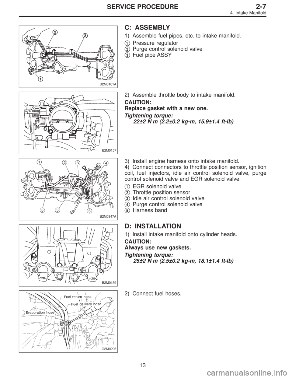
C: ASSEMBLY
1) Assemble fuel pipes, etc. to intake manifold.
�
1Pressure regulator
�
2Purge control solenoid valve
�
3Fuel pipe ASSY
B2M0157
2) Assemble throttle body to intake manifold.
CAUTION:
Replace gasket with a new one.
Tightening torque:
22±2 N⋅m (2.2±0.2 kg-m, 15.9±1.4 ft-lb)
B2M0347A
3) Install engine harness onto intake manifold.
4) Connect connectors to throttle position sensor, ignition
coil, fuel injectors, idle air control solenoid valve, purge
control solenoid valve and EGR solenoid valve.
�
1EGR solenoid valve
�
2Throttle position sensor
�
3Idle air control solenoid valve
�
4Purge control solenoid valve
�
5Harness band
B2M0159
D: INSTALLATION
1) Install intake manifold onto cylinder heads.
CAUTION:
Always use new gaskets.
Tightening torque:
25±2 N⋅m (2.5±0.2 kg-m, 18.1±1.4 ft-lb)
G2M0296
2) Connect fuel hoses.
13
2-7SERVICE PROCEDURE
4. Intake Manifold
Page 180 of 2248
B2M0362
3) Remove pressure sources switching solenoid valve
from bracket.
4) Installation is in the reverse order of removal.
Tightening torque:
6.4±0.5 N⋅m (0.65±0.05 kg-m, 4.7±0.4 ft-lb)
G2M0398
14. Fuel Injector
A: REMOVAL AND INSTALLATION
1) Release fuel pressure.
2) Disconnect connector from fuel injector.
G2M0431
3) Remove fuel injector from fuel pipe assembly.
B2M0169A
4) Installation is in the reverse order of removal.
CAUTION:
Replace O-rings and insulator.
Tightening torque:
T: 3.4±0.5 N⋅m (0.35±0.05 kg-m, 2.5±0.4 ft-lb)
�
1O-ring B
�
2O-ring A
�
3Fuel injector
�
4Insulator
�
5Fuel injector cup
G6M0095
15. Engine Control Module
A: REMOVAL AND INSTALLATION
1) Disconnect battery ground cable.
25
2-7SERVICE PROCEDURE
13. Pressure Sources Switching Solenoid Valve (AT model) - 14. Fuel Injector
Page 181 of 2248
B2M0362
3) Remove pressure sources switching solenoid valve
from bracket.
4) Installation is in the reverse order of removal.
Tightening torque:
6.4±0.5 N⋅m (0.65±0.05 kg-m, 4.7±0.4 ft-lb)
G2M0398
14. Fuel Injector
A: REMOVAL AND INSTALLATION
1) Release fuel pressure.
2) Disconnect connector from fuel injector.
G2M0431
3) Remove fuel injector from fuel pipe assembly.
B2M0169A
4) Installation is in the reverse order of removal.
CAUTION:
Replace O-rings and insulator.
Tightening torque:
T: 3.4±0.5 N⋅m (0.35±0.05 kg-m, 2.5±0.4 ft-lb)
�
1O-ring B
�
2O-ring A
�
3Fuel injector
�
4Insulator
�
5Fuel injector cup
G6M0095
15. Engine Control Module
A: REMOVAL AND INSTALLATION
1) Disconnect battery ground cable.
25
2-7SERVICE PROCEDURE
13. Pressure Sources Switching Solenoid Valve (AT model) - 14. Fuel Injector
Page 182 of 2248
B2M0362
3) Remove pressure sources switching solenoid valve
from bracket.
4) Installation is in the reverse order of removal.
Tightening torque:
6.4±0.5 N⋅m (0.65±0.05 kg-m, 4.7±0.4 ft-lb)
G2M0398
14. Fuel Injector
A: REMOVAL AND INSTALLATION
1) Release fuel pressure.
2) Disconnect connector from fuel injector.
G2M0431
3) Remove fuel injector from fuel pipe assembly.
B2M0169A
4) Installation is in the reverse order of removal.
CAUTION:
Replace O-rings and insulator.
Tightening torque:
T: 3.4±0.5 N⋅m (0.35±0.05 kg-m, 2.5±0.4 ft-lb)
�
1O-ring B
�
2O-ring A
�
3Fuel injector
�
4Insulator
�
5Fuel injector cup
G6M0095
15. Engine Control Module
A: REMOVAL AND INSTALLATION
1) Disconnect battery ground cable.
25
2-7SERVICE PROCEDURE
13. Pressure Sources Switching Solenoid Valve (AT model) - 14. Fuel Injector
Page 186 of 2248
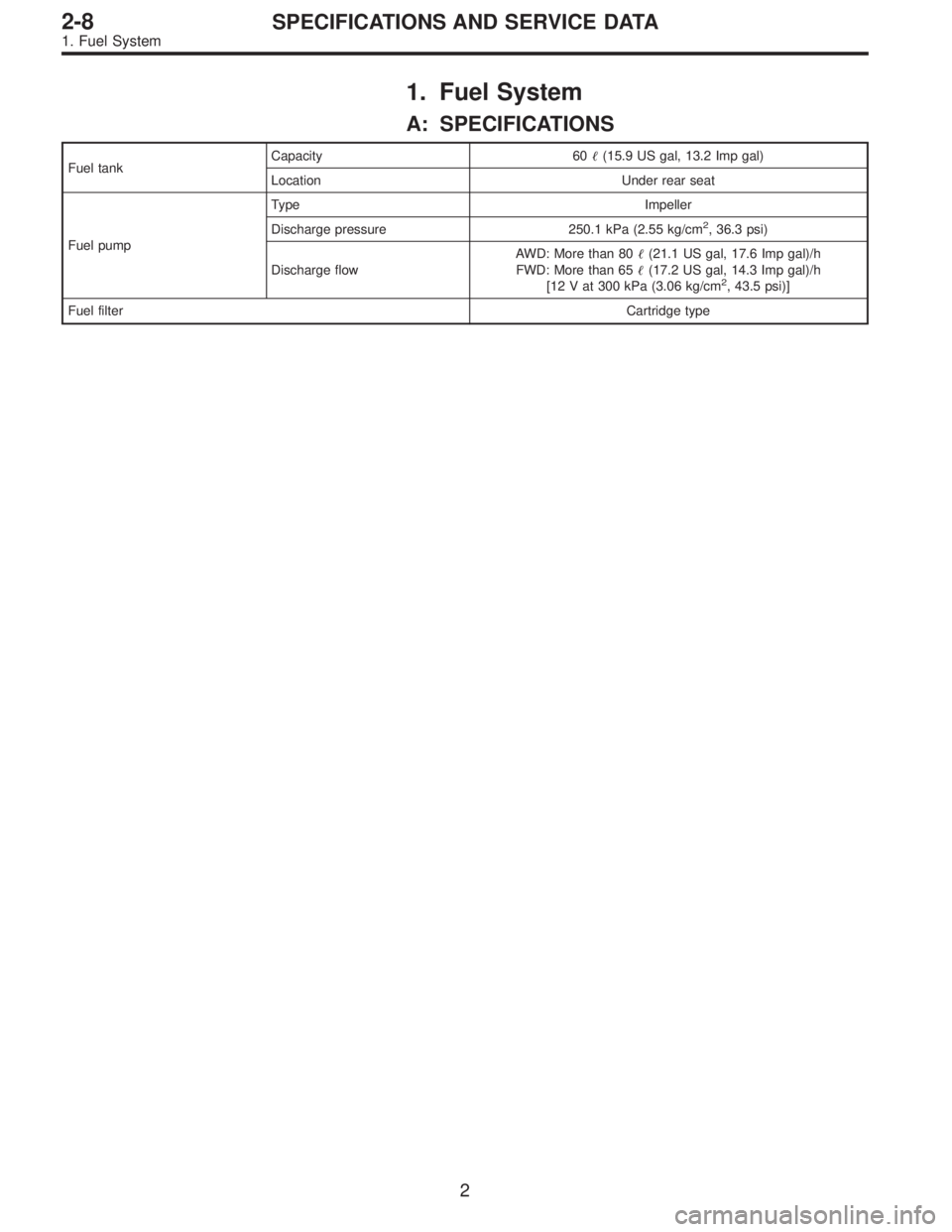
1. Fuel System
A: SPECIFICATIONS
Fuel tankCapacity 60�(15.9 US gal, 13.2 Imp gal)
Location Under rear seat
Fuel pumpType Impeller
Discharge pressure 250.1 kPa (2.55 kg/cm
2, 36.3 psi)
Discharge flowAWD: More than 80�(21.1 US gal, 17.6 Imp gal)/h
FWD: More than 65�(17.2 US gal, 14.3 Imp gal)/h
[12 V at 300 kPa (3.06 kg/cm
2, 43.5 psi)]
Fuel filterCartridge type
2
2-8SPECIFICATIONS AND SERVICE DATA
1. Fuel System
![SUBARU LEGACY 1995 Service Repair Manual B2M0154
4. Intake Manifold
A: REMOVAL
1) Release fuel pressure. <Ref. to 2-8 [W1A0].>
2) Disconnect connector from mass air flow sensor.
3) Remove air intake duct, air cleaner upper cover and air
clea](/manual-img/17/57432/w960_57432-158.png "SUBARU LEGACY 1995 Service Repair Manual B2M0154
4. Intake Manifold
A: REMOVAL
1) Release fuel pressure. <Ref. to 2-8 [W1A0].>
2) Disconnect connector from mass air flow sensor.
3) Remove air intake duct, air cleaner upper cover and air
clea")
 Disconnect connector from knock sensor.
G2M0416
18) Disconnect connector from camshaft position sensor.
G2M0408
19) Disconnect connector from crankshaft position sensor.
G2M0091
20) Discon")
 Remove bolts which hold intake manifold onto cylinder
heads.
B2M0160
23) Remove intake manifold.
B2M0347A
B: DISASSEMBLY
1) Disconnect connectors from throttle position sensor,
ignition co")
 Remove pressure sources switching solenoid valve
from bracket.
4) Installation is in the reverse order of removal.
Tightening torque:
6.4±0.5 N⋅m (0.65±0.05 kg-m, 4.7±0.4 ft-lb)
G2M039")
 Remove pressure sources switching solenoid valve
from bracket.
4) Installation is in the reverse order of removal.
Tightening torque:
6.4±0.5 N⋅m (0.65±0.05 kg-m, 4.7±0.4 ft-lb)
G2M039")
 Remove pressure sources switching solenoid valve
from bracket.
4) Installation is in the reverse order of removal.
Tightening torque:
6.4±0.5 N⋅m (0.65±0.05 kg-m, 4.7±0.4 ft-lb)
G2M039")