Page 893 of 2248
G4M0626
6) Remove compressor V-belt.
Loosen lock nut on idler pulley. Turn adjusting bolt and
remove V-belt.
G4M0627
7) Disconnect alternator harness.
G4M0628
8) Disconnect compressor harness.
Disconnect compressor harness from body harness.
9) Lower bracket.
Remove bolts which secure lower compressor bracket.
G4M0629
10) Remove compressor.
Remove bolt which secure compressor. Remove compres-
sor from bracket.
G4M0630
C: INSTALLATION
1) Install compressor.
Install compressor on bracket.
33
4-7SERVICE PROCEDURE
11. Compressor
Page 894 of 2248
 Connect compressor harness.
3) Connect alternator harness.
4) Install compressor V-belt (Rear).
After adjusting belt tension, tighten tension pulley lock nut
securely.
G4M0632
5) Install alternator")
2) Connect compressor harness.
3) Connect alternator harness.
4) Install compressor V-belt (Rear).
After adjusting belt tension, tighten tension pulley lock nut
securely.
G4M0632
5) Install alternator V-belt.
After adjusting V-belt tension, tighten alternator bracket
lock bolt securely.
6) Check drive belt tension and adjust it if necessary by
changing alternator position and/or idler pulley position.
Pulley arrangement Tension mm (in)/98N (10 kg, 22 lb)
G4M0939
AB
*New belt:
7.0—9.0
(0.276—0.354)
Existing belt:
9.0—11.0
(0.354—0.433)*New belt:
7.5—8.5
(0.295—0.335)
Existing belt:
9.0—10.0
(0.354—0.394)
* When replacing belts with new ones, adjust tensions to
specification and then readjust to the same specification
after running engine for 5 minutes.
Figures in table refer to the number of grooves in pulleys.
C/P : Crankshaft pulley
ALT : Alternator pulley
P/S : Power steering oil pump pulley
A/C : Air conditioner compressor pulley
I/P : Idler pulley
34
4-7SERVICE PROCEDURE
11. Compressor
Page 1243 of 2248
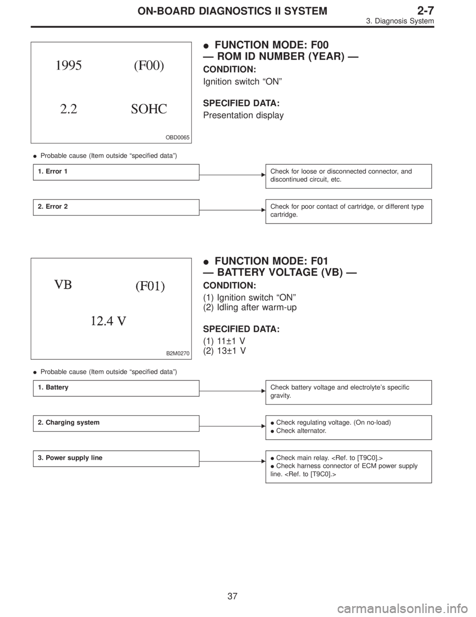
OBD0065
�FUNCTION MODE: F00
— ROM ID NUMBER (YEAR) —
CONDITION:
Ignition switch“ON”
SPECIFIED DATA:
Presentation display
�Probable cause (Item outside“specified data”)
1. Error 1
�Check for loose or disconnected connector, and
discontinued circuit, etc.
2. Error 2�Check for poor contact of cartridge, or different type
cartridge.
B2M0270
�FUNCTION MODE: F01
— BATTERY VOLTAGE (VB) —
CONDITION:
(1) Ignition switch“ON”
(2) Idling after warm-up
SPECIFIED DATA:
(1) 11±1 V
(2) 13±1 V
�Probable cause (Item outside“specified data”)
1. Battery
�Check battery voltage and electrolyte’s specific
gravity.
2. Charging system��Check regulating voltage. (On no-load)
�Check alternator.
3. Power supply line��Check main relay.
�Check harness connector of ECM power supply
line.
37
2-7ON-BOARD DIAGNOSTICS II SYSTEM
3. Diagnosis System
Page 1271 of 2248
, main relay and fuel pump relay.
CAUTION:
�All Airbag system wirin")
4. Cautions
A: SUPPLEMENTAL RESTRAINT SYSTEM
“AIRBAG”
Airbag system wiring harness is routed near the engine
control module (ECM), main relay and fuel pump relay.
CAUTION:
�All Airbag system wiring harness and connectors
are colored yellow. Do not use electrical test equip-
ment on these circuit.
�Be careful not to damage Airbag system wiring har-
ness when servicing the engine control module (ECM),
transmission control module (TCM), main relay and
fuel pump relay.
B: PRECAUTIONS
1) Never connect the battery in reverse polarity.
�The ECM will be destroyed instantly.
�The fuel injector and other part will be damaged in just
a few minutes more.
2) Do not disconnect the battery terminals while the
engine is running.
�A large counter electromotive force will be generated in
the alternator, and this voltage may damage electronic
parts such as ECM, etc.
3) Before disconnecting the connectors of each sensor
and the ECM, be sure to turn OFF the ignition switch.
4) Before removing ECM from the located position, dis-
connect two cables on battery.
�Otherwise, the ECM may be damaged.
5) The connectors to each sensor in the engine compart-
ment and the harness connectors on the engine side and
body side are all designed to be waterproof. However, it is
still necessary to take care not to allow water to get into the
connectors when washing the vehicle, or when servicing
the vehicle on a rainy day.
6) Every MFI-related part is a precision part. Do not drop
them.
7) Observe the following cautions when installing a radio
in MFI equipped models.
CAUTION:
�The antenna must be kept as far apart as possible
from the control unit.
(The ECM is located under the steering column, inside
of the instrument panel lower trim panel.)
�The antenna feeder must be placed as far apart as
possible from the ECM and MFI harness.
�Carefully adjust the antenna for correct matching.
65
2-7ON-BOARD DIAGNOSTICS II SYSTEM
4. Cautions
Page 1701 of 2248
B: ABS AND TCS WARNING LIGHT DO NOT
GO OFF.
—TCS OFF AND TCS OPERATING
INDICATOR LIGHTS COME ON AND GO OFF
PROPERLY WHEN STARTING THE ENGINE,
WHILE ABS WARNING AND TCS WARNING
LIGHTS KEEP ON.—
1. Check brake fluid level.
OK
�Not OK
Add to brake fluid.
2. Check brake fluid level sensor.
OK
�Not OK
Replace master cylinder.
3. Check harness connector between ABS/TCS
control module and alternator.
OK
�Not OK
Replace harness connector.
Replace ABS/TCS control module.
B4M0389
�
�
�
20
4-4bBRAKES
7. Diagnostics Chart for Warning Light Circuit Failure
Page 1702 of 2248
1. CHECK BRAKE FLUID LEVEL.
Check that brake fluid level is above the MIN indication on
the reservoir tank.
B4M0716A
2. CHECK BRAKE FLUID LEVEL SENSOR.
1) Turn ignition switch OFF.
2) Disconnect connector from brake fluid level sensor.
Connector & terminal / Specified resistance:
(B16) No. 1—No.2/0Ω(Leaving float where it
is.)
(B16) No. 1—No.2/1MΩ(When pushing float
down.)
B4M0717A
3. CHECK HARNESS CONNECTOR BETWEEN ABS/
TCS CONTROL MODULE AND ALTERNATOR.
1) Turn ignition switch OFF.
2) Connect connector from brake fluid level sensor.
3) Disconnect all connectors from ABS/TCS control mod-
ule.
4) Measure voltage between ABS/TCS control module
connector and body.
Connector & terminal / Specified voltage:
(P7) No. 20—body/2Vorless
5) Start the engine.
6) Measure voltage between ABS/TCS control module
connector and body.
Connector & terminal / Specified voltage:
(P7) No. 20—body / 10—14 V
21
4-4bBRAKES
7. Diagnostics Chart for Warning Light Circuit Failure
 Remove compressor V-belt.
Loosen lock nut on idler pulley. Turn adjusting bolt and
remove V-belt.
G4M0627
7) Disconnect alternator harness.
G4M0628
8) Disconnect compressor harness.
Disconn")

 Turn ignition switch OFF.
2) Disconnect conne")