Page 162 of 2248
B2M0346
17) Disconnect connector from knock sensor.
G2M0416
18) Disconnect connector from camshaft position sensor.
G2M0408
19) Disconnect connector from crankshaft position sensor.
G2M0091
20) Disconnect connector from oil pressure switch.
G2M0296
21) Disconnect fuel hoses from pipes.
WARNING:
Catch fuel from hoses in a container.
11
2-7SERVICE PROCEDURE
4. Intake Manifold
Page 165 of 2248
G2M0091
3) Connect connector to oil pressure switch.
G2M0408
4) Connect connector to crankshaft position sensor.
G2M0416
5) Connect connector to camshaft position sensor.
B2M0346
6) Connect connector to knock sensor.
B2M0345A
7) Connect connectors to engine coolant temperature sen-
sor�
1and thermometer�2.
14
2-7SERVICE PROCEDURE
4. Intake Manifold
Page 317 of 2248
 Adjustment of drive pinion shim�2
(1) Place drive pinion shaft assembly on right hand
transmission main case without shim and tighten bear-
ing mounting bolts.
(2) Inspection and adjustmen")
B3M0064A
2) Adjustment of drive pinion shim�2
(1) Place drive pinion shaft assembly on right hand
transmission main case without shim and tighten bear-
ing mounting bolts.
(2) Inspection and adjustment of ST
NOTE:
�Loosen the two bolts and adjust so that the scale indi-
cates 0.5 correctly when the plate end and the scale end
are on the same level.
�Tighten the two bolts.
ST 499917500 DRIVE PINION GAUGE ASSY
�
A: Plate
�
B: Scale
B3M0065A
(3) Position the ST by inserting the knock pin of ST into
the knock hole in the transmission case.
(4) Slide the drive pinion gauge scale with finger tip
and read the value at the point where it matches with
the end face of drive pinion.
�
C: Adjust clearance to zero without shim.
(5) The thickness of shim shall be determined by add-
ing the value indicated on drive pinion to the value
indicated on the ST. (Add if the number on drive pinion
is prefixed by + and subtract if the number is prefixed
by�.)
ST 499917500 DRIVE PINION GAUGE ASSY
Select one to three shims from the next table for the value
determined as described above and take a shim thickness
which is closest to the said value.
Drive pinion shim
Part No. Thickness mm (in)
32295AA031 0.150 (0.0059)
32295AA041 0.175 (0.0069)
32295AA051 0.200 (0.0079)
32295AA061 0.225 (0.0089)
32295AA071 0.250 (0.0098)
32295AA081 0.275 (0.0108)
32295AA091 0.300 (0.0118)
32295AA101 0.500 (0.0197)
42
3-1SERVICE PROCEDURE
4. Transmission Case
Page 318 of 2248
 Install differential assembly�3on left hand transmission
case.
CAUTION:
Be careful not to fold the sealing lip of oil seal.
NOTE:
Wrap the left and right splined sections of axle shaft with")
G3M0557
3) Install differential assembly�3on left hand transmission
case.
CAUTION:
Be careful not to fold the sealing lip of oil seal.
NOTE:
Wrap the left and right splined sections of axle shaft with
vinyl tape to prevent scratches.
G3M0558
4) Install needle bearing and oil seal onto the front of
transmission main shaft assembly�
4, and position in left
side transmission case.
CAUTION:
�Wrap clutch splined section with vinyl tape to pre-
vent damage to oil seal.
�Apply grease (Unilube #2 or equivalent) to the seal-
ing lip of oil seal.
NOTE:
�Align the end face of seal with surface A of left side
transmission main case when installing oil seal.
�Be careful not to drop oil seal when installing right side
transmission main case.
�Make sure straight pin is positioned in hole in needle
bearing’s outer race.
G3M0575
5) Install drive pinion shaft assembly�5with shims
selected before into transmission case.
NOTE:
Ensure that the knock pin of the case is fitted into the hole
in the bearing outer race.
43
3-1SERVICE PROCEDURE
4. Transmission Case
Page 328 of 2248
G3M0618
6) Install lock washer (42 x 53 x 2). Install lock nut (42 x
13) and tighten to the specified torque using ST.
ST 499987300 SOCKET WRENCH (50)
Tightening torque:
245±10 N⋅m (25±1 kg-m, 181±7 ft-lb)
B3M0079A
NOTE:
�Stake lock nut at two points.
�Using spring balancer, check that starting torque of roller
bearing�
2is 0.1 to 1.5 N⋅m (1 to 15 kg-cm, 0.9 to 13.0 in-
lb).
B3M0080A
3. DRIVE PINION SHAFT
1) Install roller bearing onto drive pinion. Install washer�
1
(33 x 50 x 5) using ST1, ST2 and press.
ST1 499277100 BUSH 1-2 INSTALLER
ST2 499277200 INSTALLER
B3M0081A
NOTE:
When installing roller bearing�
2, note its directions (front
and rear) because knock pin hole�
3in outer race is offset.
B3M0082A
2) Install thrust bearing (33 x 50 x 3) and needle bearing
(30 x 37 x 23). Install driven shaft assembly�
4.
53
3-1SERVICE PROCEDURE
5. Drive Pinion Assembly (AWD Model)
Page 344 of 2248

1. Manual Transmission and
Differential
Symptom and possible cause Remedy
1. Gears are difficult to intermesh.
The cause for difficulty in shifting gears can be classified into two kinds: one is malfunction of the gear shift system and the
other is malfunction of the transmission. However, if the operation is heavy and engagement of the gears is difficult, defective
clutch disengagement may also be responsible. Check whether the clutch is correctly functioning, before checking the gear
shift system and transmission.
(a) Worn, damaged or burred chamfer of internal spline of
sleeve and reverse driven gearReplace.
(b) Worn, damaged or burred chamfer of spline of gears Replace.
(c) Worn or scratched bushings Replace.
(d) Incorrect contact between synchronizer ring and gear
cone or wearCorrect or replace.
2. Gear slips out.
(1) Gear slips out when coasting on rough road.
(2) Gear slips out during acceleration.
(a) Defective pitching stopper adjustment Adjust.
(b) Loose engine mounting bolts Tighten or replace.
(c) Worn fork shifter, broken shifter fork rail spring Replace.
(d) Worn or damaged ball bearing Replace.
(e) Excessive clearance between splines of synchronizer hub
and synchronizer sleeveReplace.
(f) Worn tooth step of synchronizer hub (responsible for slip-
out of 3rd gear)Replace.
(g) Worn 1st driven gear, needle bearing and race Replace.
(h) Worn 2nd driven gear, needle bearing and race Replace.
(i) Worn 3rd drive gear and bushing Replace.
(j) Worn 4th drive gear and bushing Replace.
(k) Worn reverse idler gear and bushing Replace.
3. Unusual noise comes from transmission.
If an unusual noise is heard when the vehicle is parked with its engine idling and if the noise ceases when the clutch is
disengaged, it may be considered that the noise comes from the transmission.
(a) Insufficient or improper lubrication Lubricate or replace with specified oil.
(b) Worn or damaged gears and bearings Replace.
NOTE: If the trouble is only wear of the tooth surfaces, merely
a high roaring noise will occur at high speeds, but if any part
is broken, rhythmical knocking sound will be heard even at
low speeds.
69
3-1DIAGNOSTICS
1. Manual Transmission and Differential
Page 624 of 2248
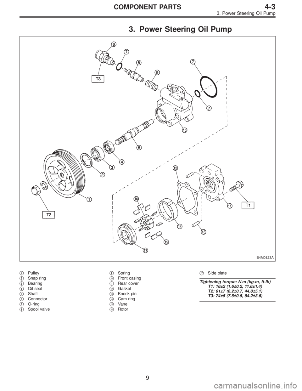
3. Power Steering Oil Pump
B4M0123A
�1Pulley
�
2Snap ring
�
3Bearing
�
4Oil seal
�
5Shaft
�
6Connector
�
7O-ring
�
8Spool valve�
9Spring
�
10Front casing
�
11Rear cover
�
12Gasket
�
13Knock pin
�
14Cam ring
�
15Vane
�
16Rotor�
17Side plate
Tightening torque: N⋅m (kg-m, ft-lb)
T1: 16±2 (1.6±0.2, 11.6±1.4)
T2: 61±7 (6.2±0.7, 44.8±5.1)
T3: 74±5 (7.5±0.5, 54.2±3.6)
9
4-3COMPONENT PARTS
3. Power Steering Oil Pump
Page 691 of 2248
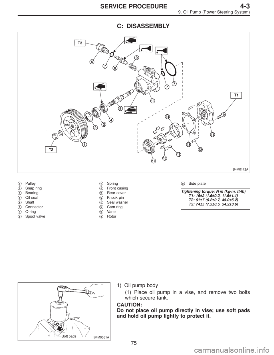
C: DISASSEMBLY
B4M0142A
�1Pulley
�
2Snap ring
�
3Bearing
�
4Oil seal
�
5Shaft
�
6Connector
�
7O-ring
�
8Spool valve�
9Spring
�
10Front casing
�
11Rear cover
�
12Knock pin
�
13Seal washer
�
14Cam ring
�
15Vane
�
16Rotor�
17Side plate
Tightening torque: N⋅m (kg-m, ft-lb)
T1: 16±2 (1.6±0.2, 11.6±1.4)
T2: 61±7 (6.2±0.7, 45.0±5.2)
T3: 74±5 (7.5±0.5, 54.2±3.6)
B4M0561A
1) Oil pump body
(1) Place oil pump in a vise, and remove two bolts
which secure tank.
CAUTION:
Do not place oil pump directly in vise; use soft pads
and hold oil pump lightly to protect it.
75
4-3SERVICE PROCEDURE
9. Oil Pump (Power Steering System)
 Disconnect connector from knock sensor.
G2M0416
18) Disconnect connector from camshaft position sensor.
G2M0408
19) Disconnect connector from crankshaft position sensor.
G2M0091
20) Discon")
 Connect connector to oil pressure switch.
G2M0408
4) Connect connector to crankshaft position sensor.
G2M0416
5) Connect connector to camshaft position sensor.
B2M0346
6) Connect connector")
 Install lock washer (42 x 53 x 2). Install lock nut (42 x
13) and tighten to the specified torque using ST.
ST 499987300 SOCKET WRENCH (50)
Tightening torque:
245±10 N⋅m (25±1 kg-m, 181")