Page 692 of 2248
G4M0178
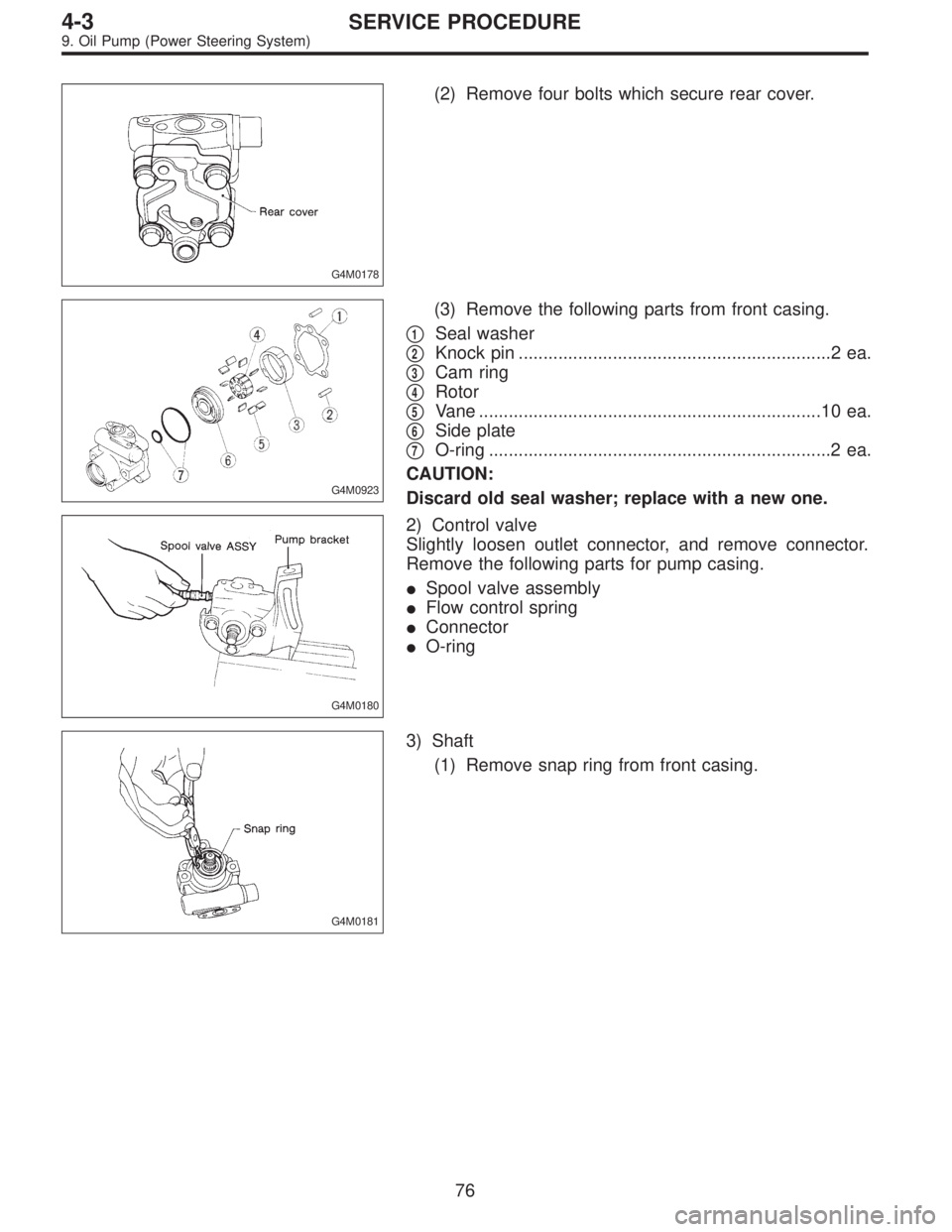
(2) Remove four bolts which secure rear cover.
G4M0923
(3) Remove the following parts from front casing.
�
1Seal washer
�
2Knock pin ...............................................................2 ea.
�
3Cam ring
�
4Rotor
�
5Vane .....................................................................10 ea.
�
6Side plate
�
7O-ring .....................................................................2 ea.
CAUTION:
Discard old seal washer; replace with a new one.
G4M0180
2) Control valve
Slightly loosen outlet connector, and remove connector.
Remove the following parts for pump casing.
�Spool valve assembly
�Flow control spring
�Connector
�O-ring
G4M0181
3) Shaft
(1) Remove snap ring from front casing.
76
4-3SERVICE PROCEDURE
9. Oil Pump (Power Steering System)
Page 695 of 2248
 Cartridge assembly
(1) Apply specified hydraulic oil to O-rings and fit them
into front casing.
(2) Install side plate to front casing.
CAUTION:
Use care not to let side plate gall.
G4M0187")
G4M0186
3) Cartridge assembly
(1) Apply specified hydraulic oil to O-rings and fit them
into front casing.
(2) Install side plate to front casing.
CAUTION:
Use care not to let side plate gall.
G4M0187
(3) Mount rotor onto shaft.
(4) Install 10 vanes into rotor with their nose radius
facing toward cam ring.
(5) Install cam ring to front casing, securing with knock
pins.
CAUTION:
Do not use hammer to fit knock pins in position.
G4M0188
4) Rear cover
(1) Mount seal washer on front casing.
(2) With knock pin positions aligned, install rear cover.
Tightening torque:
16±2 N⋅m (1.6±0.2 kg-m, 11.6±1.4 ft-lb)
CAUTION:
Loosely tighten bolts in the sequence�
1,�3,�2, and�4
shown in figure. Then, tighten in the same sequence.
G4M0189
5) Spool Valve
(1) Install spring into front casing. Then, with spool
valve dipped in specified hydraulic oil, install it into the
front casing.
(2) Using a 5-mm dia. round bar, ensure that valve
moves smoothly.
(3) Set O-ring, with grease applied to it, onto connec-
tor and secure connector to front casing.
Tightening torque:
74±5 N⋅m (7.5±0.5 kg-m, 54.2±3.6 ft-lb)
CAUTION:
�Use care to prevent damage to O-ring at installation.
�When tightening connector, ensure that O-ring does
not protrude or get caught.
79
4-3SERVICE PROCEDURE
9. Oil Pump (Power Steering System)
Page 711 of 2248

While engine is run-
ning with maximum
turning angle.
Relief valve soundGenerates at max.
turning angle.Normal (Don’t keep
this condition over 5
s")
6. NOISE AND VIBRATION
*6
Hiss noise (continu-
ous)
While engine is run-
ning with maximum
turning angle.
Relief valve soundGenerates at max.
turning angle.Normal (Don’t keep
this condition over 5
seconds.)
Generates without
steering operation.Defective
Replace oil pump.
Rattling noise
(intermittent)
While engine is run-
ning.Interference with adjacent partsCheck clearance.
[Refer to next article
6.]
Correct if necessary.
Loosened installation of oil pump, oil tank, pump bracket,
gearbox or crossmember.Retighten.
Loosened installation of oil pump pulley or other pulley(s).Retighten.
Loosened linkage or play of steering or suspension.
Loosened tightening of joint or steering column.Retighten or replace.
Sound generates from the inside of gearbox or oil pump.Replace the gearbox
or oil pump.
Knocking
When turning steer-
ing wheel in both
direction with small
angle repeatedly at
engine ON or OFF.Excessive backlash
Loosened lock nut for adjusting backlash.Adjust and retighten.
Loosened tightening or play of tie-rod, tie-rod end.Retighten or replace.
*6 Don’t keep the relief valve operated over 5 sec. at any time or inner parts of the oil pump may be damaged due to rapid increase
of fluid temperature.
95
4-3DIAGNOSTICS
1. Power Steering
Page 978 of 2248
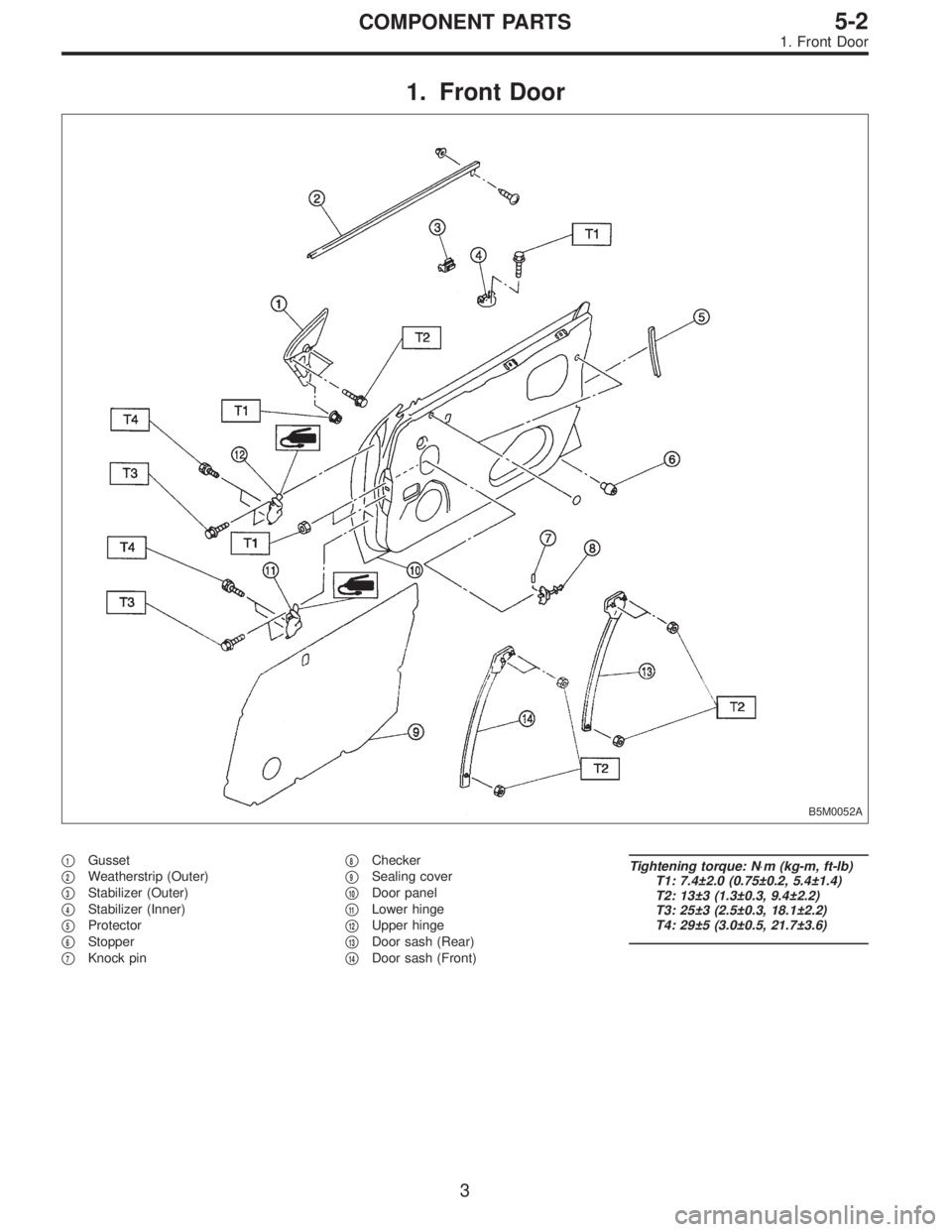
1. Front Door
B5M0052A
�1Gusset
�
2Weatherstrip (Outer)
�
3Stabilizer (Outer)
�
4Stabilizer (Inner)
�
5Protector
�
6Stopper
�
7Knock pin�
8Checker
�
9Sealing cover
�
10Door panel
�
11Lower hinge
�
12Upper hinge
�
13Door sash (Rear)
�
14Door sash (Front)
Tightening torque: N⋅m (kg-m, ft-lb)
T1: 7.4±2.0 (0.75±0.2, 5.4±1.4)
T2: 13±3 (1.3±0.3, 9.4±2.2)
T3: 25±3 (2.5±0.3, 18.1±2.2)
T4: 29±5 (3.0±0.5, 21.7±3.6)
3
5-2COMPONENT PARTS
1. Front Door
Page 979 of 2248
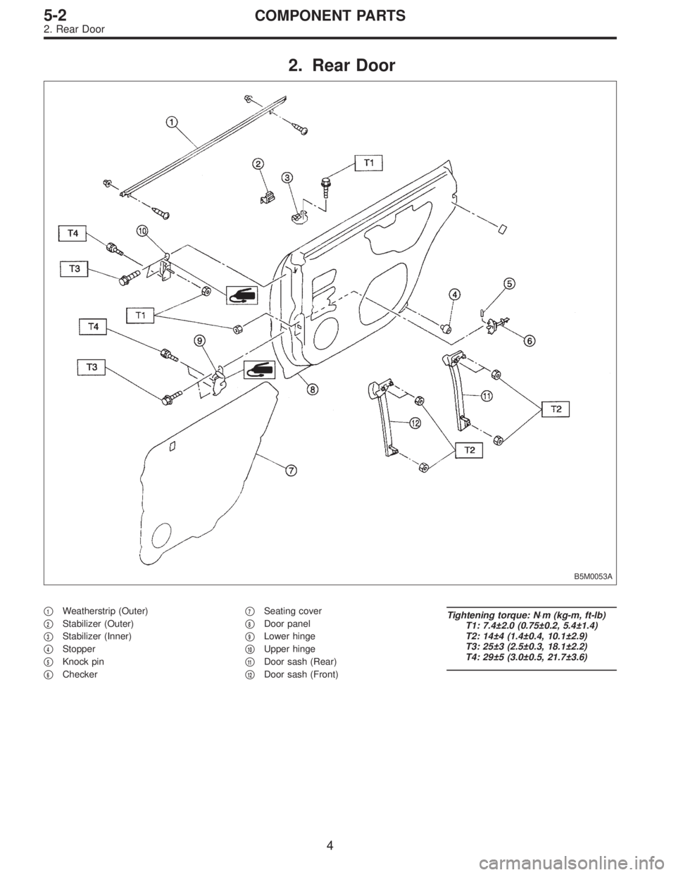
2. Rear Door
B5M0053A
�1Weatherstrip (Outer)
�
2Stabilizer (Outer)
�
3Stabilizer (Inner)
�
4Stopper
�
5Knock pin
�
6Checker�
7Seating cover
�
8Door panel
�
9Lower hinge
�
10Upper hinge
�
11Door sash (Rear)
�
12Door sash (Front)
Tightening torque: N⋅m (kg-m, ft-lb)
T1: 7.4±2.0 (0.75±0.2, 5.4±1.4)
T2: 14±4 (1.4±0.4, 10.1±2.9)
T3: 25±3 (2.5±0.3, 18.1±2.2)
T4: 29±5 (3.0±0.5, 21.7±3.6)
4
5-2COMPONENT PARTS
2. Rear Door
Page 1211 of 2248

�
2Ignition coil
�
3Ignitor
�
4Crankshaft position sensor
�
5Camshaft position sensor
�
6Throttle position sensor
�
7Fuel injectors
�
8Pressure regulator
�
9Engine coolan")
�1Engine control module (ECM)
�
2Ignition coil
�
3Ignitor
�
4Crankshaft position sensor
�
5Camshaft position sensor
�
6Throttle position sensor
�
7Fuel injectors
�
8Pressure regulator
�
9Engine coolant temperature sensor
�
10Mass air flow sensor
�
11Idle air control solenoid valve
�
12Purge control solenoid valve
�
13Fuel pump
�
14PCV valve
�
15Air cleaner
�
16Canister
�
17Main relay
�
18Fuel pump relay
�
19Fuel filter
�
20Front catalytic converter
�
21Rear catalytic converter
�
22EGR valve�
23EGR control solenoid valve
�
24Radiator fan
�
25Radiator fan relay
�
26Pressure sources switching solenoid valve (AT vehicles only)
�
27Knock sensor
�
28Back-pressure transducer (AT vehicles only)
�
29Front oxygen sensor
�
30Rear oxygen sensor
�
31Pressure sensor (AT vehicles only)
�
32A/C compressor
�
33Inhibitor switch
�
34CHECK ENGINE malfunction indicator lamp (MIL)
�
35Tachometer
�
36A/C relay
�
37A/C control module
�
38Ignition switch
�
39Transmission control module (TCM) (AT vehicles only)
�
40ABS/TCS control module (TCS equipped models)
�
41Vehicle speed sensor
�
42Data link connector (Subaru select monitor)
�
43Data link connector (OBD-II general scan tool)
�
44Two way valve
5
2-7ON-BOARD DIAGNOSTICS II SYSTEM
1. General
Page 1216 of 2248
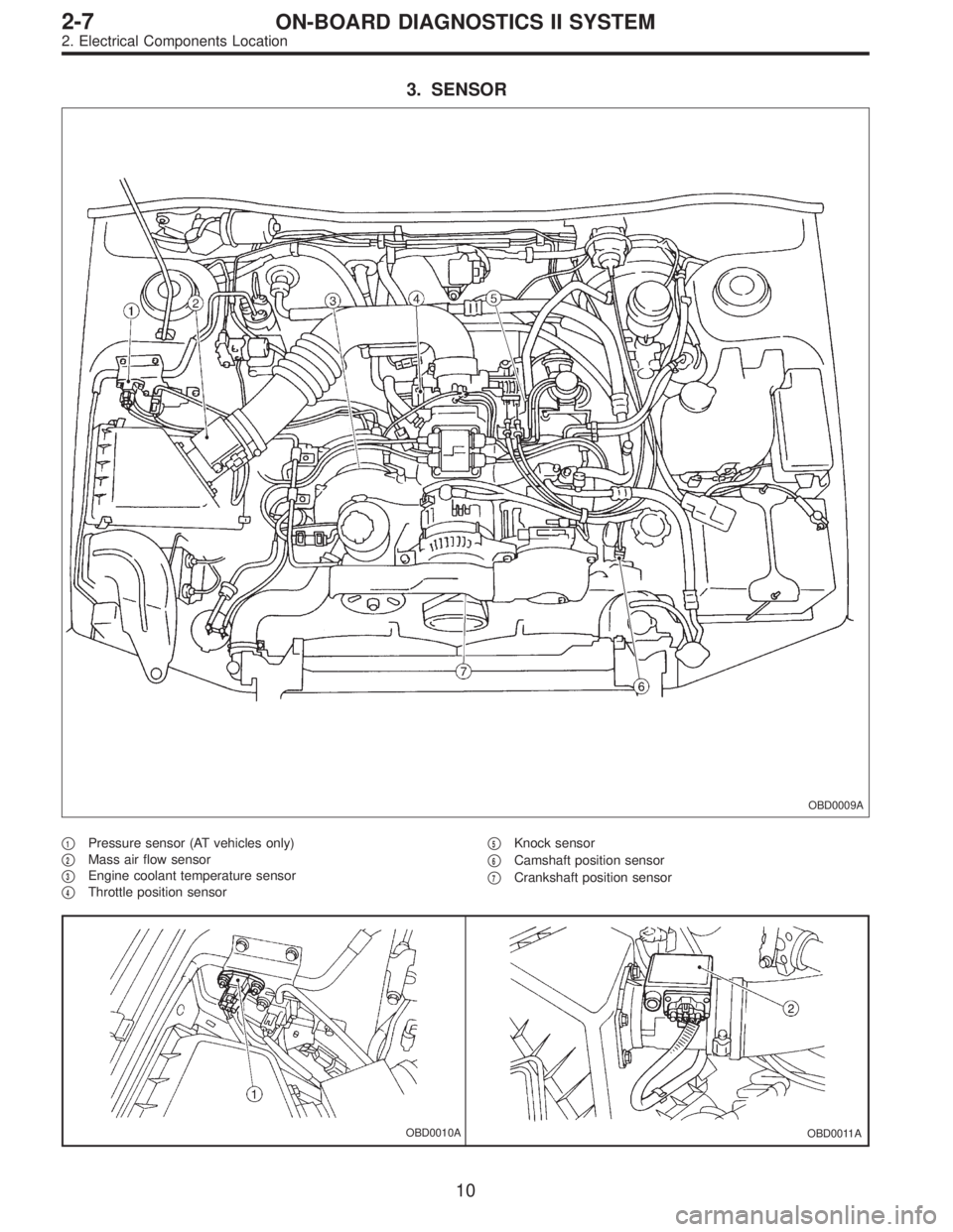
3. SENSOR
OBD0009A
�1Pressure sensor (AT vehicles only)
�
2Mass air flow sensor
�
3Engine coolant temperature sensor
�
4Throttle position sensor�
5Knock sensor
�
6Camshaft position sensor
�
7Crankshaft position sensor
OBD0010AOBD0011A
10
2-7ON-BOARD DIAGNOSTICS II SYSTEM
2. Electrical Components Location
Page 1241 of 2248

2. READ DATA FUNCTION KEY LIST FOR ENGINE
Function mode Contents Abbreviation Unit of measure
F00 ROM ID number YEAR—
F01 Battery voltage VB V
F02 Vehicle speed signal VSP m/h
F03 Vehicle speed signal VSP km/h
F04 Engine speed signal EREV rpm
F05 Engine coolant temperature signal TW°F
F06 Engine coolant temperature signal TW°C
F07 Ignition signal ADVS deg
F08 Mass air flow signal QA V
F09 Load data DATA—
F10 Throttle position signal THV V
F11 Injector pulse width TIM mS
F12 Idle air control signal ISC %
F13 Front oxygen sensor output signal FO2 V
F14 Front oxygen sensor maximum output signal FO2max V
F15 Front oxygen sensor minimum output signal FO2min V
F16 Rear oxygen sensor output signal RO2 V
F17 Rear oxygen sensor maximum output signal RO2max V
F18 Rear oxygen sensor minimum output signal RO2min V
F19 Short term fuel trim ALPHA %
F20 Knock sensor signal RTRD deg
F21 A/F correction (short term trim) by rear oxygen sensor PHOS %
F23 Atmospheric absolute pressure signal (AT vehicles) BARO. P V
F24 Intake manifold absolute pressure signal (AT vehicles) MANI. P V
F25 Long term fuel trim KBLRC %
F28 Long term whole fuel trim K0 %
F29 Front oxygen sensor heater current FO2H A
F30 Rear oxygen sensor heater current RO2H A
F33Maximum value of cylinder #1 misfire times during 200
rotationsMF1 %
F34Maximum value of cylinder #2 misfire times during 200
rotationsMF2 %
F35Maximum value of cylinder #3 misfire times during 200
rotationsMF3 %
F36Maximum value of cylinder #4 misfire times during 200
rotationsMF4 %
F37 Maximum EGR system pressure value (AT vehicles) EGRmax mmHg
F38 Minimum EGR system pressure value (AT vehicles) EGRmin mmHg
F45 Load data LOAD %
F46 Throttle position signal THV %
F47 Mass air flow signal QA g/s
F48 Atmospheric absolute pressure signal BARO. P kPa
F49 Intake manifold absolute pressure signal MANI. P kPa
35
2-7ON-BOARD DIAGNOSTICS II SYSTEM
3. Diagnosis System