Page 293 of 1701
Pistonbootretainer (AD22VF only)
Piston boot
Piston seal
FRONT
DISCBRAKE
Inspection -Caliper (Cont'd)
PISTON
Check pistonforscore, rust,wear, damage orpresence offor-
eign objects. Replace ifany ofthe above conditions are
observed.
CAUTION:
Piston sliding surface isplated. Donot polish withemery paper
even ifrust orforeign objects arestuck tosliding surface.
SLIDE PIN,PINBOLT ANDPINBOOT
Check forwear, cracks, rustorother damage. Replaceifany of
the above conditions areobserved.
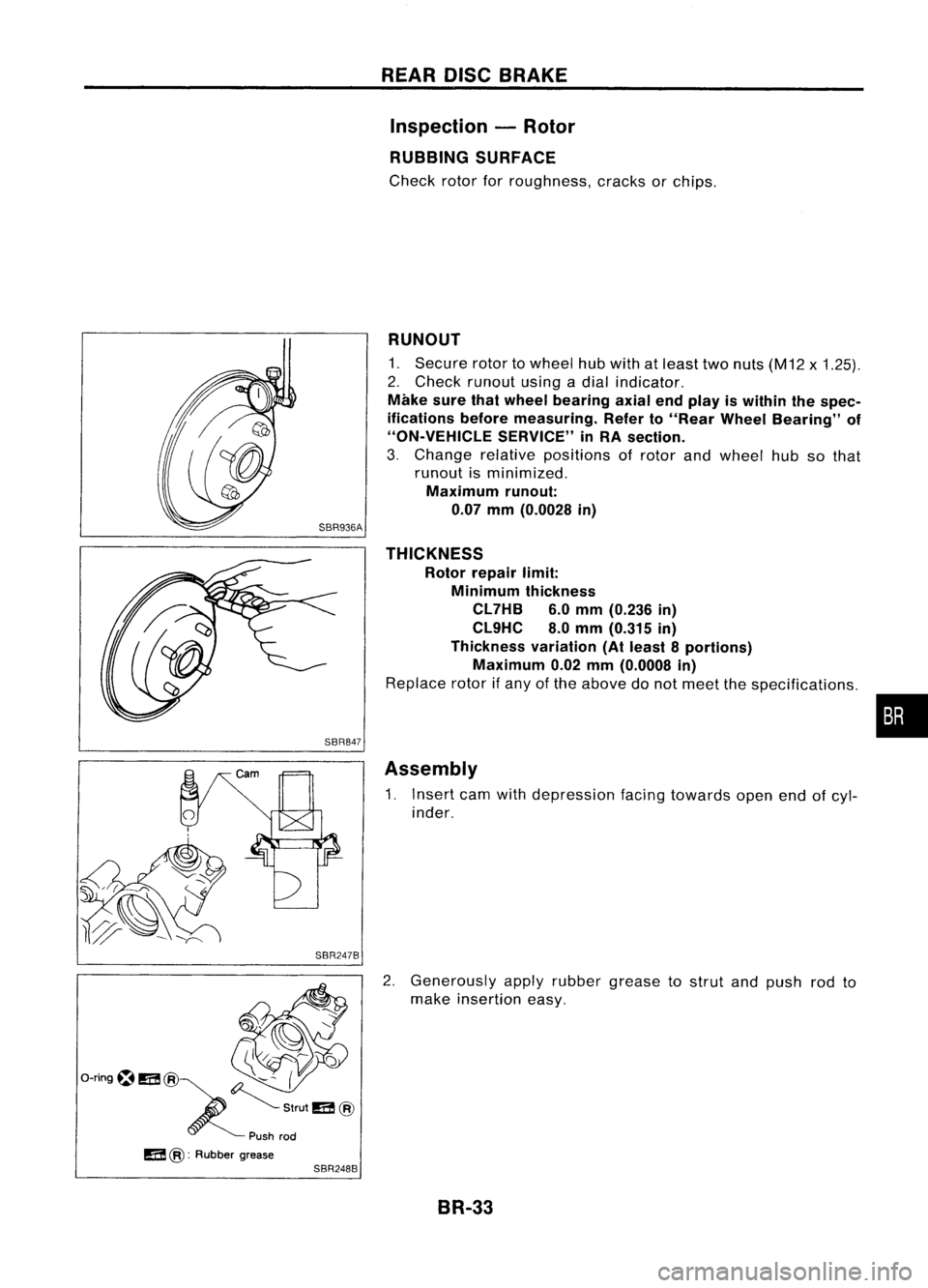
Inspection -Rotor
RUNOUT
1: Secure rotortowheel hubwith atleast twonuts (M12 x
1.25).
2. Check runout usingadial indicator.
Make surethatwheel bearing axialendplay iswithin thespec-
ifications beforemeasuring. RefertoFA section ("FrontWheel
Bearing", "ON-VEHICLE SERVICE").
Maximum runout:
SBR936A 0.07mm(0.0028 in)
3.
If
the runout isout ofspecification, findminimum runout
position asfollows:
a. Remove nutsandrotor fromwheel hub.
b. Shift therotor onehole andsecure rotortowheel hub
with nuts.
c. Measure runout.
d. Repeat stepsa.to c.so that minimum runoutposition can
be found.
4. Ifthe runout isstill outofspecification, turnrotor withon-car
brake lathe("MAD, DL-8700", "AMMCO700and 705" or•••
equivalent).
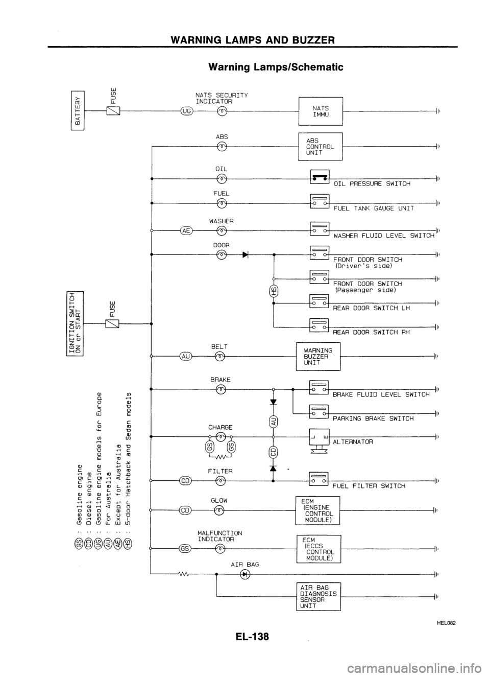
THICKNESS Thickness variation(Atleast 8positions):
Maximum 0.02mm(0.0008 in)
If thickness variationexceedsthespecification, turnrotor with
on-car brakelathe.
Rotor repair limit:
CL22VD andCL22VE 16.0mm(0.630 in)
CL22VF 24.0mm(0.945 in)
SBR944A Assembly
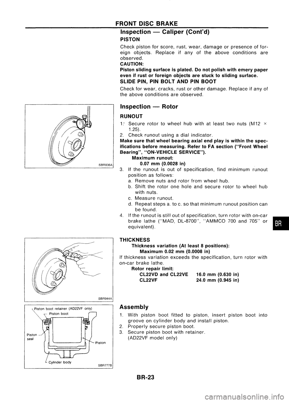
1. With piston bootfitted topiston, insertpiston bootinto
groove oncylinder bodyandinstall piston.
2. Properly securepistonboot.
3. Secure pistonbootwithretainer.
(AD22VF modelonly)
Piston
SBR777B BR-23
Page 303 of 1701
SBR847
SBR247B REAR
DISCBRAKE
Inspection -Rotor
RUBBING SURFACE
Check rotorforroughness, cracksorchips.
RUNOUT
1. Secure rotortowheel hubwith atleast twonuts (M12 x1.25).
2. Check runout usingadial indicator.
Make surethatwheel bearing axialendplay iswithin thespec-
ifications beforemeasuring. Referto"Rear Wheel Bearing" of
"ON-VEHICLE SERVICE"inRA section.
3. Change relativepositions ofrotor andwheel hubsothat
runout isminimized.
Maximum runout:
0.07 mm(0.0028 in)
THICKNESS Rotor repair limit:
Minimum thickness
CL7HB 6.0mm (0.236 in)
CL9HC 8.0mm (0.315 in)
Thickness variation(Atleast 8portions)
Maximum 0.02mm(0.0008 in)
Replace rotorifany ofthe above donot meet thespecifications .
Assembly
1. Insert camwithdepression facingtowards openendofcyl-
inder.
2. Generously applyrubber grease tostrut andpush rodto
make insertion easy.
BR-33
•
Page 510 of 1701
WARNINGLAMPSANDBUZZER
Warning Lamps/Schematic
>-
[[
W
f-
f-
CD
w
(f)
:J
l.L
UG
NATS
SECURITY
INDICATOR
NATSIMMU
ABS ABS
CONTROL
UNIT
OIL OILPRESSURE SWITCH
FUEL
FUELTANKGAUGE UNIT
WASHER
WASHERFLUIDLEVELSWITCH
DOOR
FRONTDOORSWITCH
(Driver's side)
FRONT DOORSWITCH
(Passenger side)
REAR ODOR SWITCH LH
ALTERNATOR PARKING
BRAKESWITCH
FUEL FILTER SWITCH
=
BRAKE
FLUIDLEVEL SWITCH
REAR
ODORSWITCH RH
=
WARNING
BUZZER
UNIT
=
ECM (ECCS
CONTROL
MODULE)
ECM
(ENGINE
CONTROL
MODULE)
I
U
f- W
H (f)
3:f-
:J
(f)[[
l.L
Zf-
O(f)
H
f-L
HO
Z
BELT
C!JZ
HO
BRAKE
Q)
(I)
D.
rl
0
Q)
L
D
::J
0
W
E
L
C
0
ro
""-
D
Q)
(I)
(f)
rl
Q)
ro
D
D
'M
C
0
rl
ro
E
ro
L
~
Q) Q)
.....
u
C C
(I)
ro
.M
Q)
.M
ro
::J
.0
OJ
C
OJ
.M
.c
c
.M
C
rl
U
Q)
OJ
Q)
ro
L
+'
C
L
0
ro
Q) Q) Q)
.....
""-
I
C C
(I)
GLOW
.M
rl
.
M
::J
.....
L
rl
Q)
rl
D.
0
0
(I)
0
Q)
0
(I)
Q)
(I)
L
u
D
ro
.M
ro
0
x
I
C!J
0
C!J
l.L
W
lD
MALFUNCTION
@@~@@@
INDICATOR
AIRBAG
AIRBAG
DIAGNOSIS
SENSOR
UNIT
HEL082
EL-138
Page 687 of 1701
SMA525AON-VEHICLE
SERVICE
Front AxleandFront Suspension Parts
Check frontaxleandfront suspension partsforexcessive play,
cracks, wearorother damage.
• Shake eachfrontwheel tocheck forexcessive play.
• Make surethatcotter pinsareinserted.
• Retighten allaxle andsuspension nutsandbolts tothe
specified torque.
Tightening torque:
Refer toFRONT SUSPENSION (FA-24).
Strut
Ball
joint
SFA392B
•
Check strut(shock absorber) foroilleakage orother dam-
age.
• Check suspension balljoint forgrease leakage andball
joint dustcover forcracks orother damage.
If ball joint dustcover iscracked ordamaged, replacetrans-
verse link.
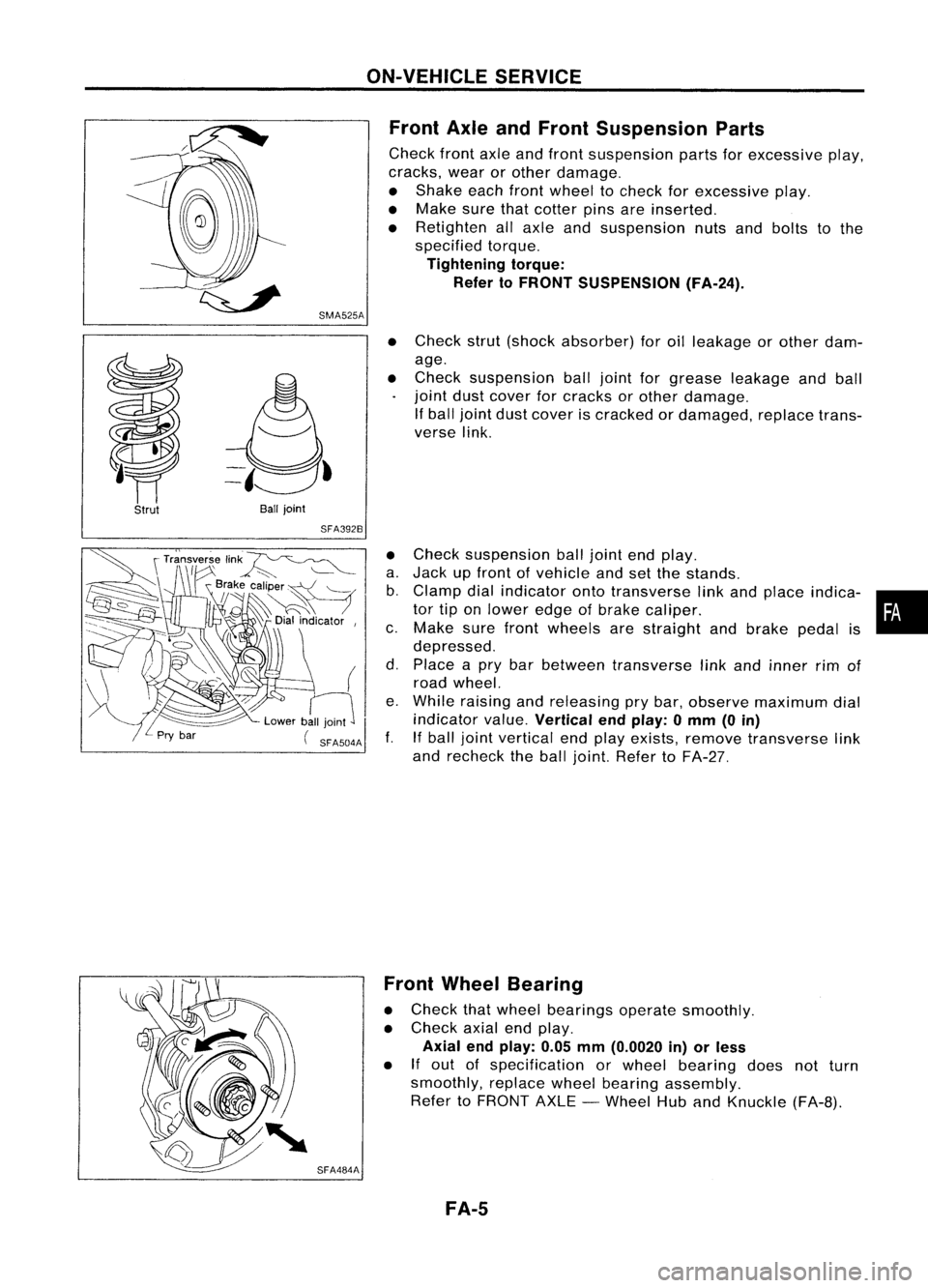
• Check suspension balljoint endplay.
a. Jack upfront ofvehicle andsetthe stands.
b. Clamp dialindicator ontotransverse linkand place indica- •
tor tiponlower edgeofbrake caliper. •
c. Make surefront wheels arestraight andbrake pedalis
depressed.
d. Place apry bar between transverse linkand inner rimof
road wheel.
e. While raising andreleasing prybar, observe maximum dial
indicator value.
Vertical endplay: 0mm (0in)
f. Ifball joint vertical endplay exists, remove transverse link
and recheck theball joint. Refer toFA-27.
SFA484A Front
Wheel Bearing
• Check thatwheel bearings operatesmoothly.
• Check axialendplay.
Axial endplay: 0.05mm(0.0020 in)orless
• If
out ofspecification orwheel bearing doesnotturn
smoothly, replacewheelbearing assembly.
Refer toFRONT AXLE-Wheel HubandKnuckle (FA-B).
FA-5