Page 1261 of 1701
OILSEAL REPLACEMENT
VALVE OILSEAL
1. Remove accelerator cable.
2. Remove rockercoverandoilseparator.
3. Remove camshafts andsprockets.
Refer to"Removal" in"TIMING CHAIN"(EM-69).
4. Remove sparkplugs.
5. Install airhose adapter intospark plugholeandapply air
pressure tohold valves inplace. Applyapressure of490
kPa (4.9bar, 5kg/cm
2,
71psi).
6. Remove rockerarm,rocker armguide andshim.
Air SEM077D
7.Remove valvespring withTool.
Piston concerned shouldbeset atTOe toprevent valvefrom
falling.
8. Remove valveoilseal.
9. Apply engine oiltonew valve oilseal andinstall itwith Tool.
FRONT OILSEAL
1. Remove thefollowing parts:
• Engine undercover
• Front RHwheel andengine sidecover
• Drive belts
• Crankshaft pulley
2. Remove frontoilseal.
Be careful nottoscratch frontcover.
SEM997C EM-82
Page 1278 of 1701
SEM092DENGINE
REMOVAL
WARNING:
• Situate vehicle onaflat and solid surface.
• Place chocks atfront andback ofrear wheels.
• Donot remove engineuntilexhaust systemhascompletely
cooled off.
Otherwise, youmay burn yourself and/orfiremay break out
in fuel line.
• For safety during subsequent steps,thetension ofwires
should beslackened againsttheengine.
• Before disconnecting fuelhose, release fuelpressure from
fuel line.
Refer to"Releasing FuelPressure" inEC section.
• Besure tohoist engine andtransaxle inasafe manner.
• For engines notequipped withengine slingers, attach
proper slingers andbolts described inPARTS CATALOG.
CAUTION:
• When liftingengine, becareful nottostrike adjacent parts,
especially thefollowing: Accelerator wirecasing, brake
lines, andbrake master cylinder.
• Inhoisting theengine, alwaysuseengine slingers inasafe
manner.
Removal
1. Remove engineundercoverandhood.
2. Drain coolant frombothcylinder block,andradiator.
3. Drain engine oilfrom drain plugofoil pan.
4. Remove vacuumhoses,fuelhoses, wires,harness andcon-
nectors andsoon.
5. Remove exhausttubes,balljoints anddrive shafts.
6. Remove radiatorandfans.
7. Remove drivebelts.
8. Remove alternator, compressor andpower steering oil
pump fromengine.
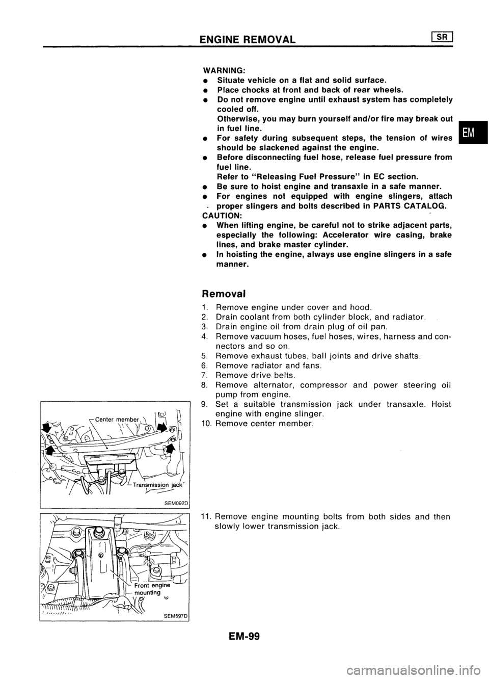
9. Set asuitable transmission jackunder transaxle. Hoist
engine withengine slinger.
10. Remove centermember.
11. Remove enginemounting boltsfrombothsides andthen
slowly lowertransmission jack.
EM-99
•
Page 1292 of 1701
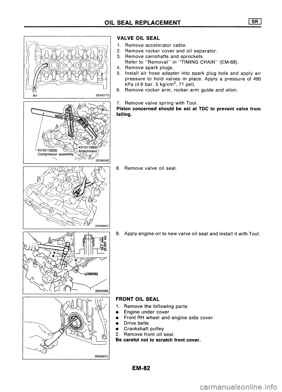
Rightside
SEC. 130.135.185.186.210.213.233
~: N.m(kg-m. in-Ib)
[ClJ :
N.m (kg-m. ft-Ib)
OUTER
COMPONENT PARTS
I~
16-21
(1.6 -2.1,
12-
15)7
I
.~
SEM044FA
•
G)
Starter motor
@
Injection pump
@
Injection tube
@
Thermostat housing
@
Injection nozzle
@
Spill tube
!J)
Water outlet
@
Beltcover
EM-113
@
Timing belt
@
Injection pumpsprocket
@
Rear camshaft sprocket
@
Rear backcover
@
Oilcooler
@
Gasket
Page 1293 of 1701
OUTERCOMPONENT PARTS
Left side
SEC. 120.135.140.210.230
l"J
16•21 (1.6 .2.1. 12•
7
<, ~
~
/
7~
~ 16-21 (1.6 •2.1, 12•15)~~""
Ii] :
N.m (kg-m, in-Ib)
~ :N.m (kg-m, fl-Ib)
L
~-@@~
-@
~18•22 (1.8 -2.2, 13.16)
6
/
~~ ~2.75(6.3.7.6,46 -55)
SEM045FA
CD
Beltcover upper
@
Water pumppulley
@
Beltcover lower
@
Crankshaft pulley
@
Alternator
@
Alternator bracket
EM-114
(J)
Exhaust manifold
@
Gasket
@
Intake manifold
Page 1299 of 1701
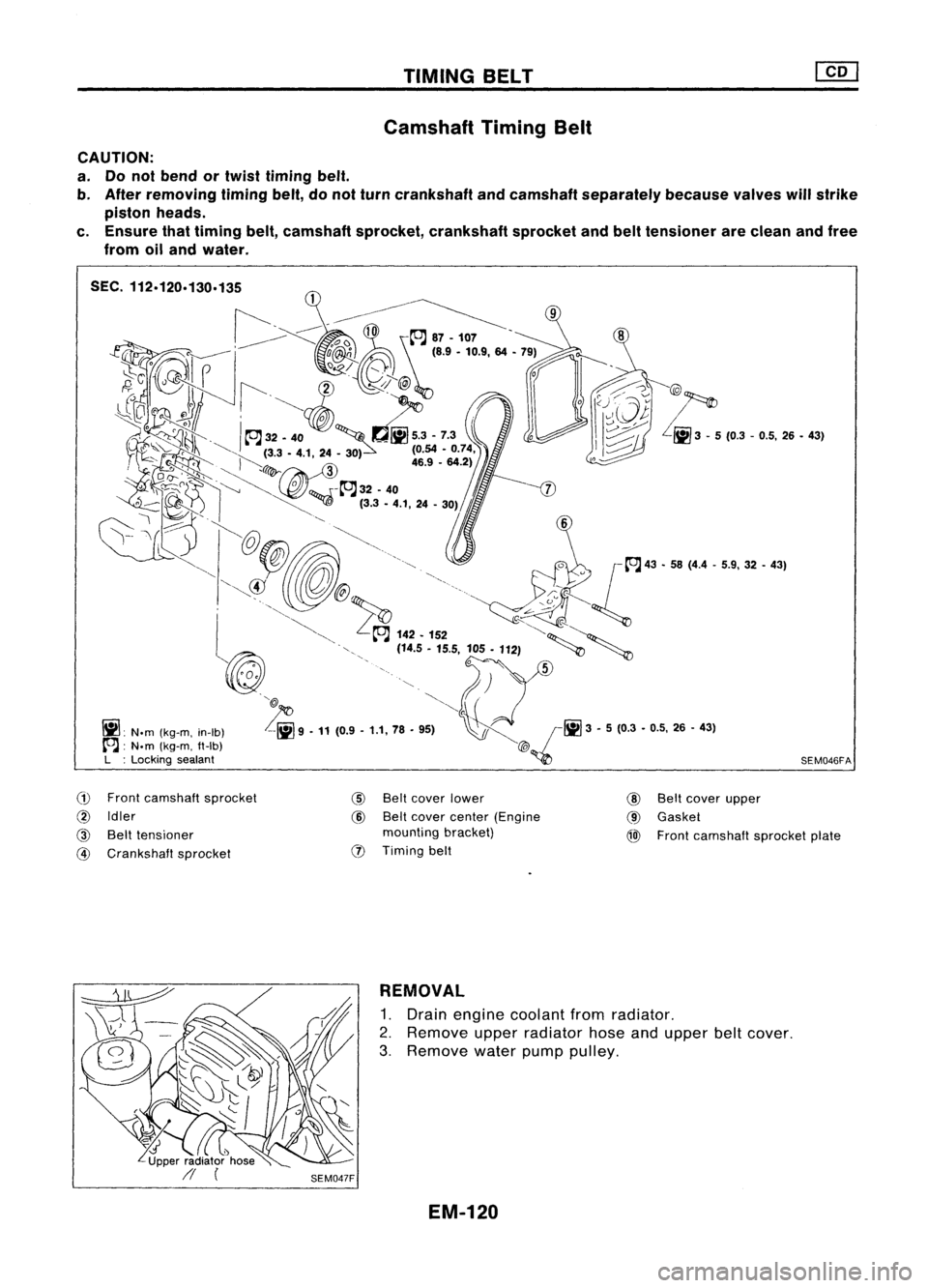
TIMINGBELT
Camshaft TimingBelt
CAUTION:
a. Donot bend ortwist timing belt.
b. After removing timingbelt,donot turn crankshaft andcamshaft separately becausevalveswillstrike
piston heads.
c. Ensure thattiming belt,camshaft sprocket,crankshaft sprocketandbelttensioner areclean andfree
from oiland water.
~: N.m(kg-m, in-Ib)
A:
N.m(kg-m, ft-Ib)
L :Locking sealant
C"O
Front camshaft sprocket
@
Idler
@
Belttensioner
@
Crankshaft sprocket
@
Beltcover lower
@
Beltcover center (Engine
mounting bracket)
(1)
Timing belt
@)
~5 {O.'-0.5, "-
43'
SEM046FA
@
Beltcover upper
@
Gasket
@)
Front camshaft sprocketplate
REMOVAL
1. Drain engine coolant fromradiator.
2. Remove upperradiator hoseandupper beltcover.
3. Remove waterpumppulley.
EM-120
Page 1300 of 1701
SEM520DSEM515D TIMING
BELT
em
Camshaft TimingBelt(Cont'd)
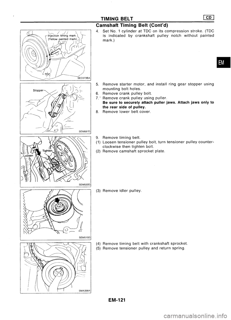
4. Set NO.1 cylinder atTDC onitscompression stroke.(TDC
is indicated bycrankshaft pulleynotchwithout painted
mark.)
5. Remove startermotor,andinstall ringgear stopper using
mounting boltholes.
6. Remove crankpulley bolt.
7 .. Remove crankpulley usingpuller.
Be sure tosecurely attachpullerjaws.Attach jawsonlyto
the rear sideofpulley.
8. Remove lowerbeltcover.
9. Remove timingbelt.
(1) Loosen tensioner pulleybolt,turntensioner pulleycounter-
clockwise thentighten bolt.
(2) Remove camshaft sprocketplate.
(3) Remove idlerpulley.
(4) Remove timingbeltwith crankshaft sprocket.
(5) Remove tensioner pulleyandreturn spring.
EM-121
•
Page 1301 of 1701
TIMINGBELT
Camshaft TimingBelt(Cont'd)
INSPECTION
Timing belt
Visually checkthecondition oftiming belt.
Replace ifany abnormality isfound.
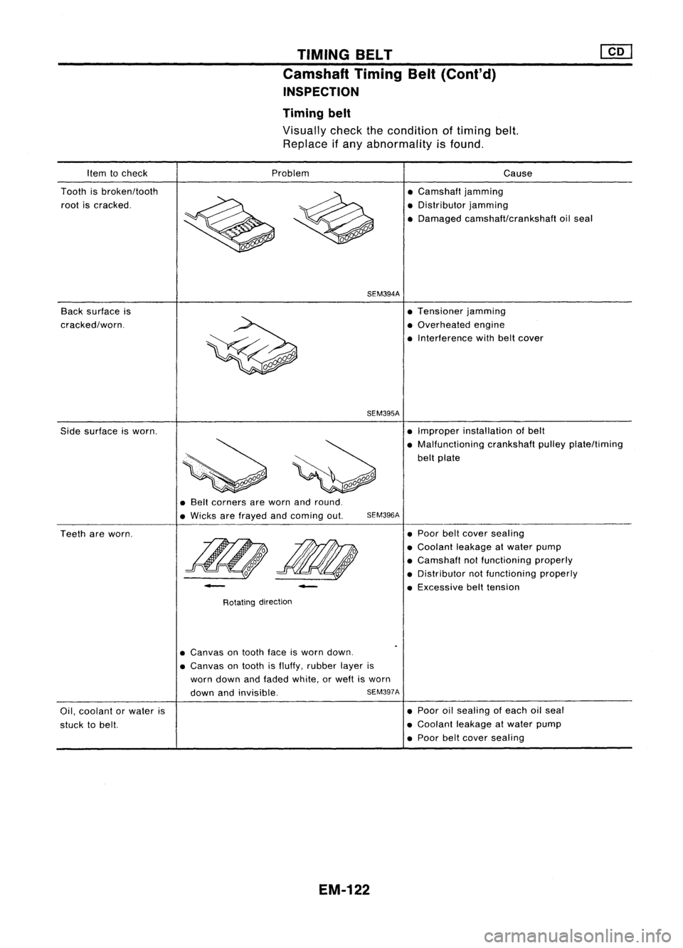
Item tocheck
Tooth isbroken/tooth
root iscracked.
Back surface is
cracked/worn. Problem
SEM394A
SEM395A
Cause
• Camshaft jamming
• Distributor jamming
• Damaged camshaft/crankshaft oilseal
• Tensioner jamming
• Overhe
ed
engine
• Interference withbeltcover
Side surface isworn. •
Improper installation ofbelt
• Malfunctioning crankshaftpulleyplate/timing
belt plate
• Belt corners areworn andround.
• Wicks arefrayed andcoming out.
SEM396A
Teeth areworn.
-
Rotating direction
-
•
Poor belt
cover
sealing
• Coolant leakageatwater pump
• Camshaft notfunctioning properly
• Distributor notfunctioning properly
• Excessive belttension
Oil, coolant orwater is
stuck tobelt.
•
Canvas
ontooth faceisworn down.
• Canvas
ontooth isfluffy, rubber layeris
worn down andfaded white, orweft isworn
down andinvisible.
SEM397A
EM-122
•
Poor oilsealing ofeach oilseal
• Coolant leakageatwater pump
• Poor belt
cover
sealing
Page 1302 of 1701
SEM558
SEM517D
SEM518D TIMING
BELT
[f[]
Camshaft TimingBelt(Cont'd)
Belt tensioner, tensionerspringandidler
1. Check belttensioner andidler forsmooth turning.
2. Check condition oftensioner spring.
Crankshaft sprocketandfront camshaft sprocket
Check teethforabnormal signs.
INSTALLATION
1. Install crankshaft sprocketplateincorrect direction.
2. Confirm thatNO.1 piston isset atTDC onitscompression
stroke. (TDCisindicated bycrankshaft pulleynotchwithout
painted mark.)
3. Install tensioner andreturn spring.
Temporarily tightenboltssothat tensioner isset atthe fully
outside position.
4. Install idlerandtighten bolttothe specified torque.
EM-123
•
![NISSAN ALMERA N15 1995 Service Manual OUTERCOMPONENT PARTS
Left side
SEC. 120.135.140.210.230
l"J
16•21 (1.6 .2.1. 12•
7
<, ~
~
/
7~
~ 16-21 (1.6 •2.1, 12•15)~~""
Ii] :
N.m (kg-m, in-Ib)
~ :N.m (kg-m, fl-Ib)
L](/manual-img/5/57349/w960_57349-1292.png "NISSAN ALMERA N15 1995 Service Manual OUTERCOMPONENT PARTS
Left side
SEC. 120.135.140.210.230
l\"J
16•21 (1.6 .2.1. 12•
7
<, ~
~
/
7~
~ 16-21 (1.6 •2.1, 12•15)~~\"\"
Ii] :
N.m (kg-m, in-Ib)
~ :N.m (kg-m, fl-Ib)
L")
![NISSAN ALMERA N15 1995 Service Manual SEM558
SEM517D
SEM518D TIMING
BELT
[f[]
Camshaft TimingBelt(Cont'd)
Belt tensioner, tensionerspringandidler
1. Check belttensioner andidler forsmooth turning.
2. Check condition oftensioner spr](/manual-img/5/57349/w960_57349-1301.png "NISSAN ALMERA N15 1995 Service Manual SEM558
SEM517D
SEM518D TIMING
BELT
[f[]
Camshaft TimingBelt(Cont'd)
Belt tensioner, tensionerspringandidler
1. Check belttensioner andidler forsmooth turning.
2. Check condition oftensioner spr")