Page 528 of 1701
WARNINGLAMPSANDBUZZER
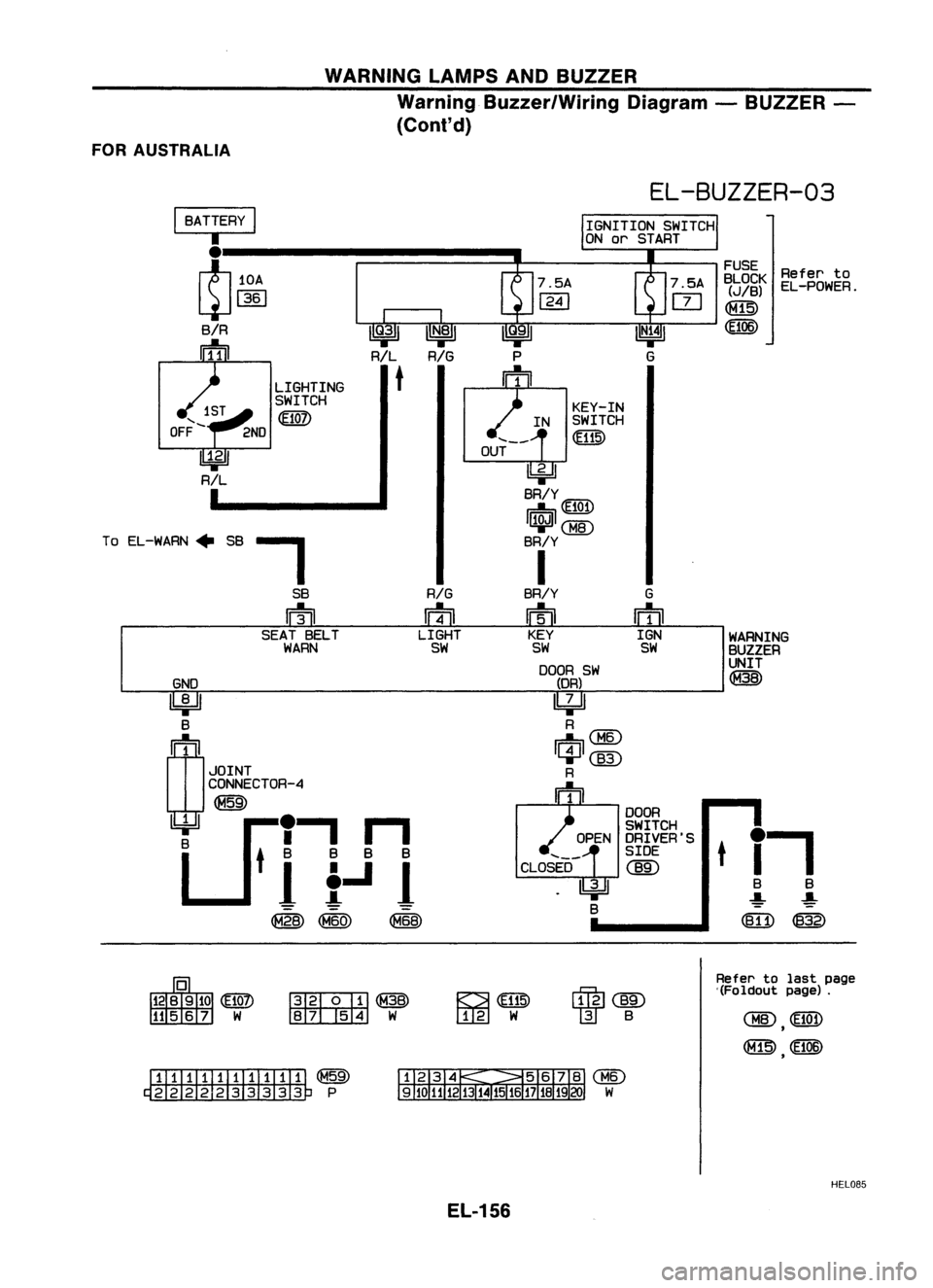
Warning Buzzer/Wiring Diagram-BUZZER -
(ConI' d)
FOR AUSTRALIA
GND
~ B
rn
1
JOINT
CONNECTOR-4
~
U
'I
n
8
tit.Ji
@
Refer
to
EL-POWER.
WARNING
BUZZER
UNIT
@
FUSE
BLOCK
(JIB)
~
t
i-,
B B
-:!:- ~
([fi) ~
EL-BUZZER-03
KEY-IN
IN SWITCH
@
OUT
~
BR/Y
~ 101
~CBID
BR/Y
I
BR/Y G
m
ffi
KEY IGN
SW SW
DOOR SW
(DR)
~
R
Ii1=nCBID
~@)
R
m
DOOR
SWITCH
OPEN DRIVER'S
SIDE
CLOSED
@)
~
B
LIGHTING
SWITCH
m
-,
SB
RIG
rn
ffi
SEAT BELT LIGHT
WARN SW
I
BATTERY
I
I
~10A
L:J
1361
SiR
rrfnJ
To EL-WARN" SB
~@
~W
~
[I[g]
W
~@)
W
B
Refer
tolast page
'(Foldout page).
ITIillJIIIIII1T ~
~P
HEL085
EL-156
Page 726 of 1701
PRECAUTIONSANDPREPARATION
Supplemental RestraintSystem(SRS)"AIR
BAG" (DualAirBag System)
The Supplemental RestraintSystem"AirBag", usedalong withaseat belt,helps toreduce therisk or
severity ofinjury tothe driver andfront passenger inafrontal collision. TheSupplemental Restraint
System consists ofair bag modules (locatedinthe center ofthe steering wheelandonthe instrument
panel onthe passenger side),adiagnosis sensorunit,warning lamp,wiring harness andspiral cable.
Information necessarytoservice thesystem safelyisincluded inthe
RSsection
ofthis Service Manual.
WARNING:
• Toavoid rendering theSRS inoperative, whichcouldincrease therisk ofpersonal injuryordeath
in the event ofacollision whichwould resultinair bag inflation, allmaintenance mustbeperformed
by an authorized NISSANdealer. •
• Improper maintenance, includingincorrectremovalandinstallation ofthe SRS, canlead topersonal
injury caused byunintentional activationofthe system.
• Donot use electrical testequipment ~nany circuit related tothe SRS unless instructed tointhis
Service Manual. SRSwiring harnesses arecovered withyellow insulation eitherjustbefore the
harness connectors orfor the complete harness,foreasy identification.
Supplemental RestraintSystem(SRS)"AIR
BAG" (Single AirBag System)
The Supplemental RestraintSystem"AirBag", usedalong withaseat belt, helps toreduce therisk or
severity ofinjury tothe driver inafrontal collision. TheSupplemental RestraintSystemconsists ofan
air bag module (located inthe center ofthe steering wheel),adiagnosis sensorunit,warning lamp,
wiring harness andspiral cable. Information necessarytoservice thesystem safelyisincluded inthe
RS section
ofthis Service Manual.
WARNING: • Toavoid rendering theSRS inoperative, whichcouldincrease therisk ofpersonal injuryordeath
in the event ofacollision whichwould resultinair bag inflation, allmaintenance mustbeperformed
by an authorized NISSANdealer.
• Improper maintenance, includingincorrectremovalandinstallation ofthe SRS, canlead topersonal
injury caused byunintentional activationofthe system.
• Donot use electrical testequipment onany circuit related tothe SRS unless instructed tointhis
Service Manual.
EC-7
Page 1091 of 1701
VE-TVPEINJECTION PUMP
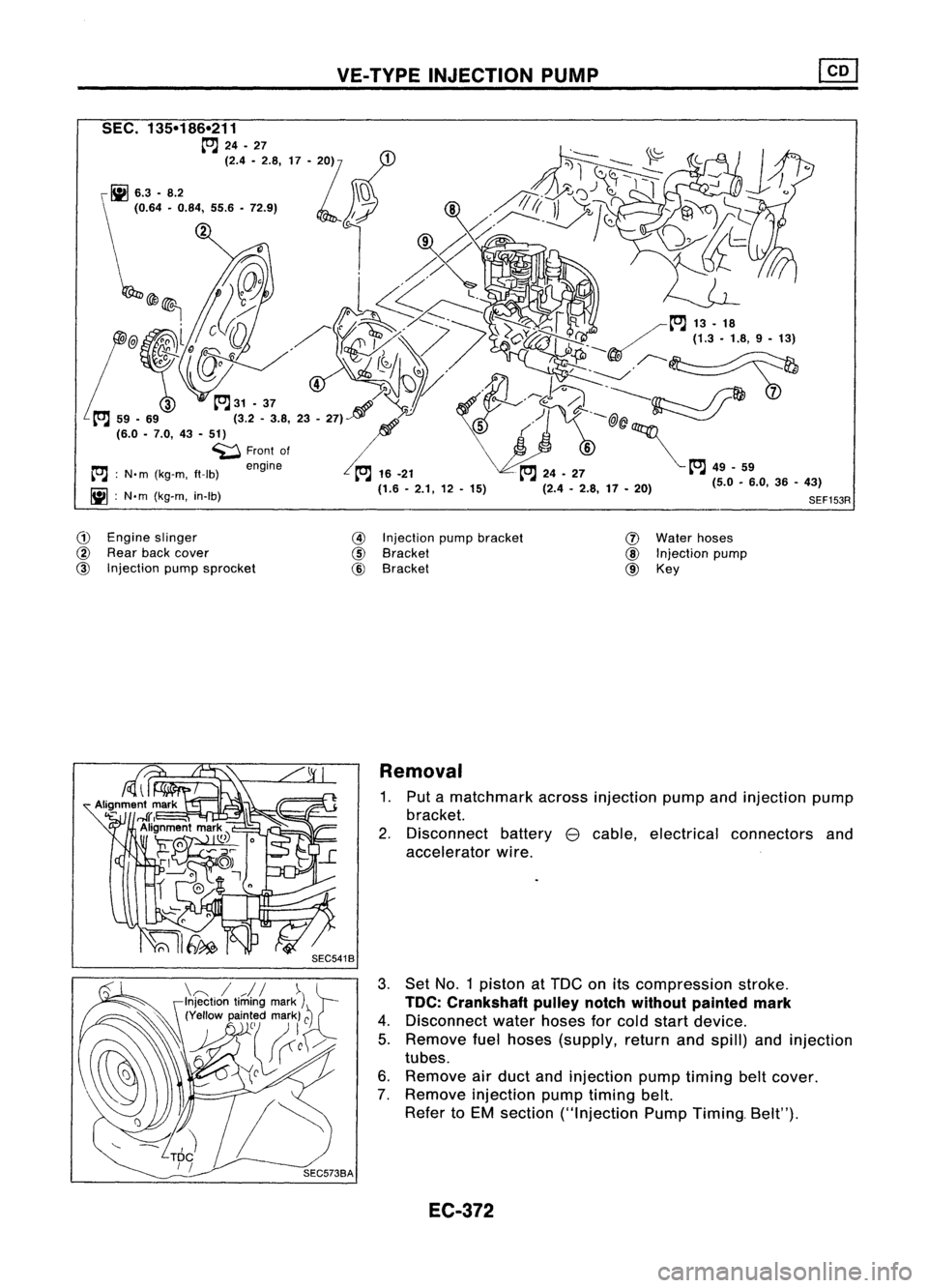
G)
Engine slinger
@
Rear backcover
@
Injection pumpsprocket
@
Injection pumpbracket
@
Bracket
@
Bracket
(J)
Water hoses
@
Injection pump
@ Key
Removal
1. Put amatchmark acrossinjection pumpandinjection pump
bracket.
2. Disconnect battery
e
cable, electrical connectors and
accelerator wire.
3. Set No.1 piston atTDe onitscompression stroke.
TOC: Crankshaft pulleynotchwithout painted mark
4. Disconnect waterhoses forcold start device.
5. Remove fuelhoses (supply, returnandspill) andinjection
tubes.
6. Remove airduct andinjection pumptiming beltcover.
7. Remove injection pumptiming belt.
Refer toEM section ("Injection PumpTiming. Belt").
EC-372
Page 1092 of 1701
VE-TVPEINJECTION PUMP ~
Removal (Cont'd)
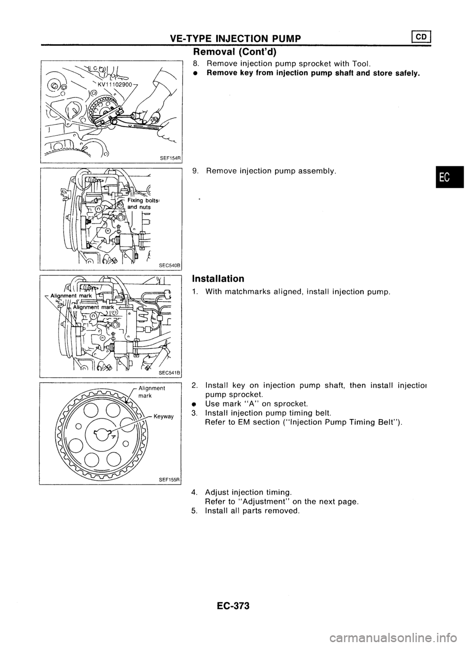
8. Remove injection pumpsprocket withTool.
• Remove keyfrom injection pumpshaftandstore safely .
9. Remove injection pumpassembly.
Installation
1. With matchmarks aligned,installinjection pump.
2. Install keyoninjection pumpshaft,theninstall injectiol
pump sprocket.
• Use mark "A"onsprocket.
3. Install injection pumptiming belt.
Refer toEM section ("Injection PumpTiming Belt").
SEF155R
4.Adjust injection timing.
Refer to"Adjustment" onthe next page.
5. Install allparts removed.
EC-373
•
Page 1151 of 1701
ENGINECOOLING SYSTEM
IiJ
6.28 -8.34 (0.641 -0.851, 55.6-73.8)
SEC.
210 Water
Pump
~ 6.28 -8.34 (0.641 -0.851, 55.6-73.8)
WaterpumppUlley
l
~Liquid gasket
~ N.m(kg-m, in-Ib)
SLC989AB
•
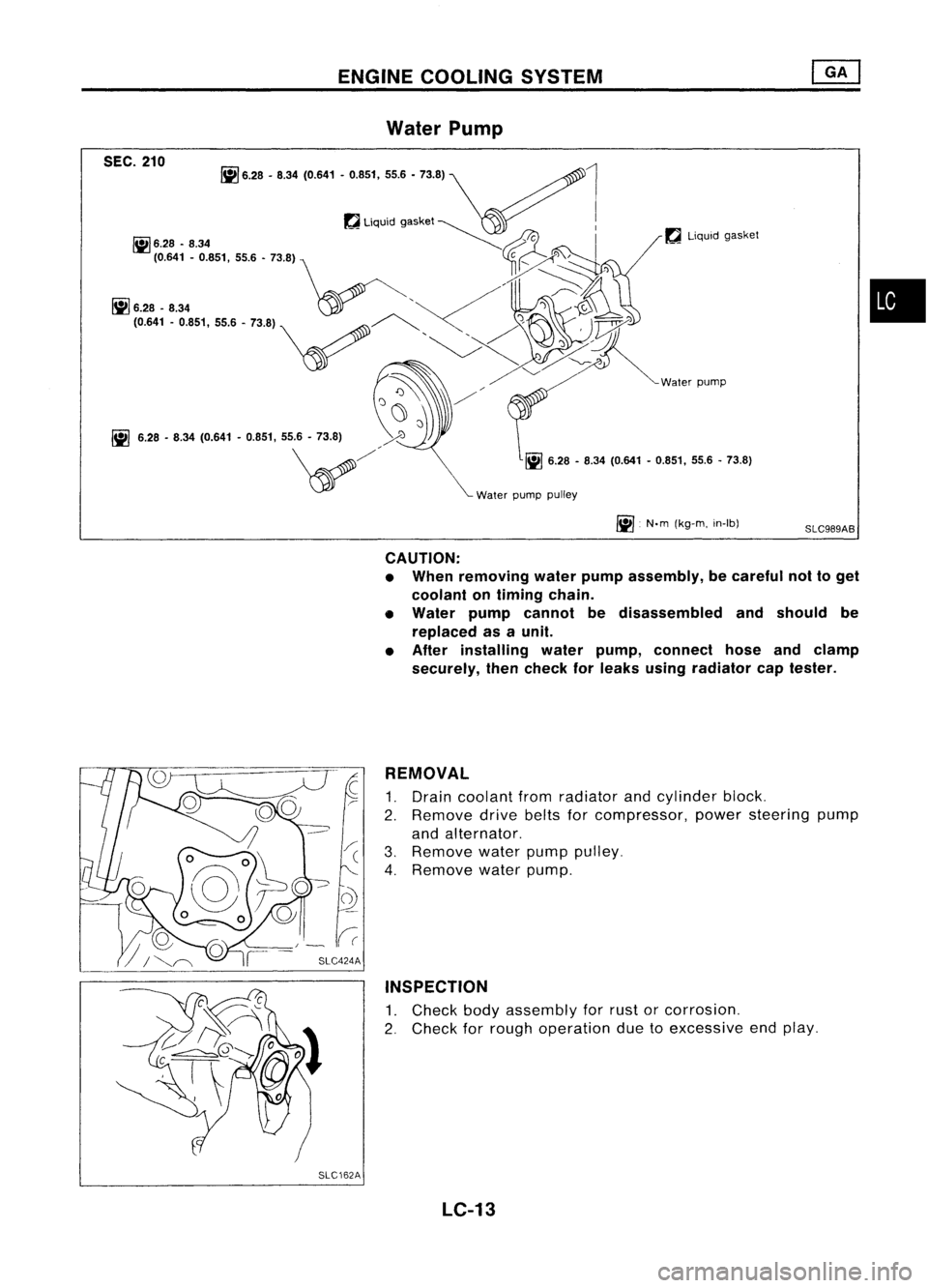
CAUTION:
• When removing waterpumpassembly, becareful nottoget
coolant ontiming chain.
• Water pumpcannot bedisassembled andshould be
replaced asaunit.
• After installing waterpump, connect hoseandclamp
securely, thencheck forleaks using radiator captester.
REMOVAL
1. Drain coolant fromradiator andcylinder block.
2. Remove drivebeltsforcompressor, powersteering pump
and alternator.
3. Remove waterpumppulley.
4. Remove waterpump.
INSPECTION
1. Check bodyassembly forrust orcorrosion.
2. Check forrough operation duetoexcessive endplay.
SLC162A LC-13
Page 1156 of 1701
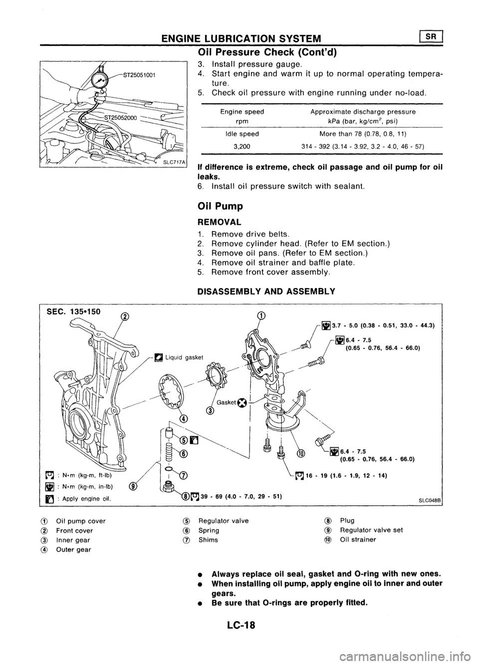
Ifdifference isextreme, checkoilpassage andoilpump foroil
leaks.
6. Install oilpressure switchwithsealant.
Approximate
dischargepressure
kPa (bar,
kg/cm
2, psi)
More than78(0.78, 0.8,11)
314 -392 (3.14 -3.92, 3.2-4.0, 46-57)
Engine
speed
rpm
Idle speed
3,200
ENGINE
LUBRICATION SYSTEM ~
Oil Pressure Check(Conl'd)
3. Install pressure gauge.
4. Start engine andwarm itup tonormal operating tempera-
ture.
5. Check oilpressure withengine running underno-load.
Oil Pump
REMOVAL
1. Remove drivebelts.
2. Remove cylinderhead.(Refer toEM section.)
3. Remove oilpans. (Refer toEM section.)
4. Remove oilstrainer andbaffle plate.
5. Remove frontcover assembly.
DISASSEMBLY ANDASSEMBLY
SLC048B
r~3.7
-
5.0 (0.38 -0.51, 33.0-44.3)
_d!:,
r!il6.4 .
7.5
o -----~
(0.65•0.76, 56.4•66.0)
-----
~
\" ~•.•-7.'
(0.65 •0.76, 56.4-66.0)
~ [OJ16•19 (1.6 -1.9, 12-14)
~[OJ39 -69 (4.0 -7.0, 29-51)
~
liquid gasket
[OJ :N'm (kg-m, ft-Ib)
~ :N.m (kg-m, in-Ib)
I) :
Apply
engine oil.
G)
Oilpump cover
@
Front cover
@
Inner gear
@
Outer gear
@
Regulator valve
@
Spring
(J)
Shims
@
Plug
@
Regulator valveset
@
Oilstrainer
• Always replace oilseal, gasket andO-ring withnewones.
• When installing oilpump, applyengine oiltoinner andouter
gears.
• Besure thatO-rings areproperly fitted.
LC-18
Page 1160 of 1701
A16-21
N.m ~/
(1.6 •2.1 kg-m,
12 -15
ft.lb)
ENGINE
COOLING SYSTEM
Cooling SystemInspection (Cont'd)
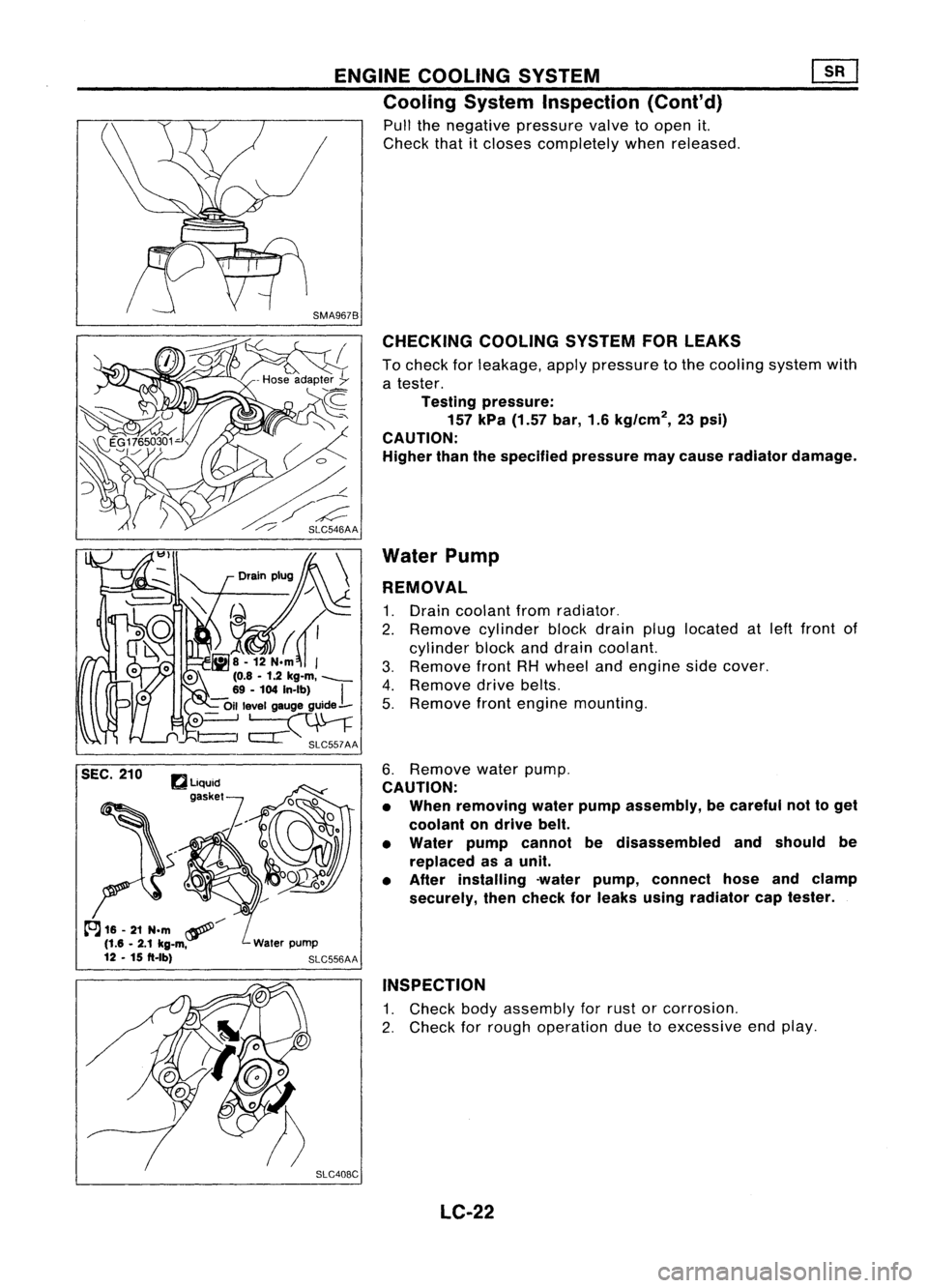
Pull thenegative pressure valvetoopen it.
Check thatitcloses completely whenreleased.
CHECKING COOLINGSYSTEMFORLEAKS
To check forleakage, applypressure tothe cooling systemwith
a tester.
Testing pressure:
157 kPa (1.57 bar,1.6kg/cm
2,
23psi)
CAUTION:
Higher thanthespecified pressuremaycause radiator damage.
Water Pump
REMOVAL
1. Drain coolant fromradiator.
2. Remove cylinderblockdrain pluglocated atleft front of
cylinder blockanddrain coolant.
3. Remove frontRHwheel andengine sidecover.
4. Remove drivebelts.
5. Remove frontengine mounting.
6. Remove waterpump.
CAUTION:
• When removing waterpumpassembly, becareful nottoget
coolant ondrive belt.
• Water pumpcannot bedisassembled andshould be
replaced asaunit.
• After installing -waterpump, connect hoseandclamp
securely, thencheck forleaks using radiator captester.
INSPECTION
1. Check bodyassembly forrust orcorrosion.
2. Check forrough operation duetoexcessive endplay.
SLC408C LC-22
Page 1165 of 1701
ENGINELUBRICATION SYSTEM
SLC926.A Ifdifference isextreme, checkoilpassage andoilpump foroil
leaks.
6. Install oilpressure switchwithsealant.
ST25052000
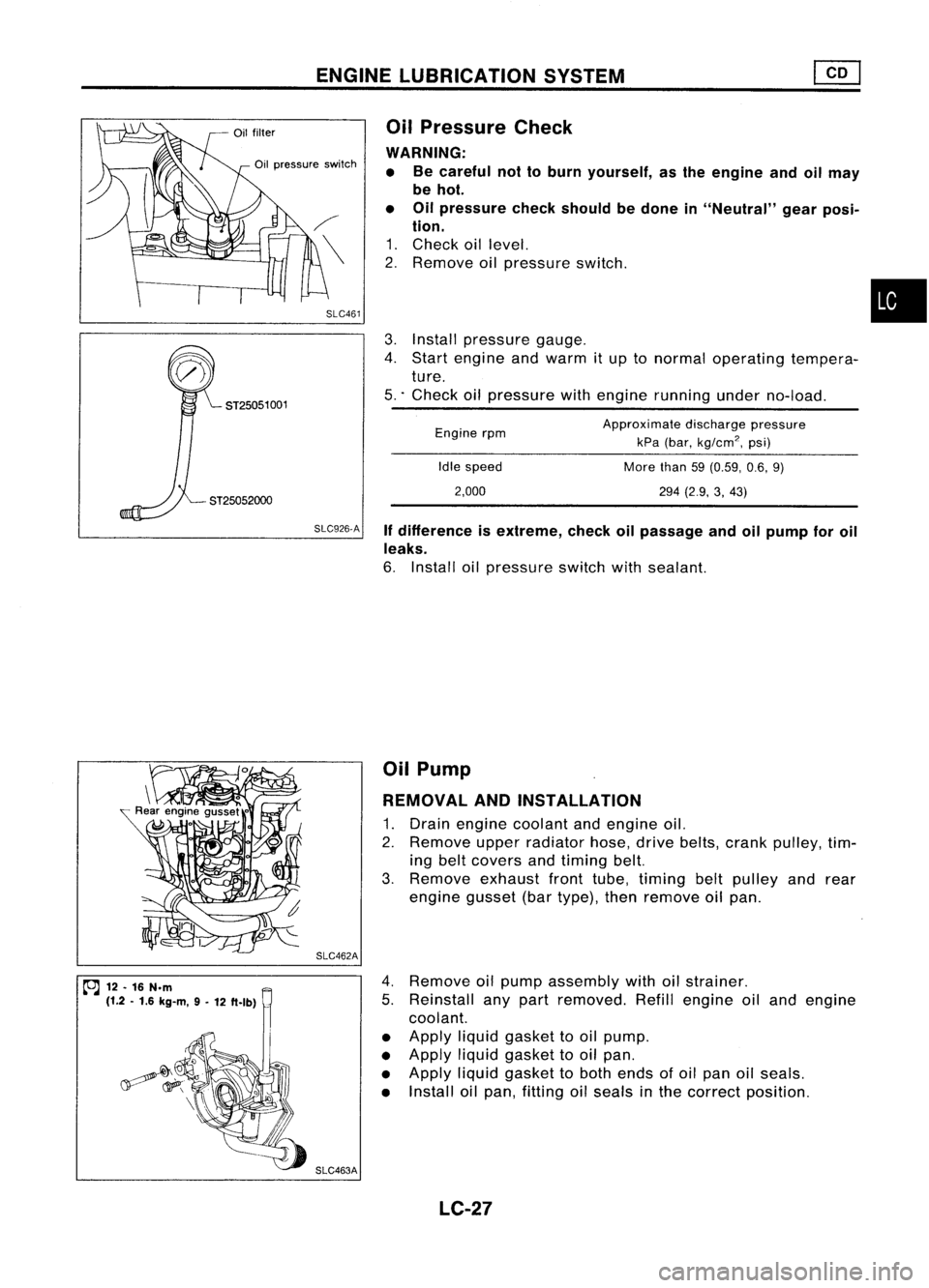
3.
Install pressure gauge.
4. Start engine andwarm itup tonormal operating tempera-
ture.
5 .. Check oilpressure withengine running underno-load.
•
Approximate dischargepressure
kPa (bar,
kg/cm
2,
psi)
More than59(0.59, 0.6,9)
294 (2.9, 3,43)
Idle
speed
2,000
Engine
rpm
Oil
Pressure Check
WARNING: • Becareful nottoburn yourself, asthe engine andoilmay
be hot.
• Oilpressure checkshould bedone in"Neutral" gearposi-
tion.
1. Check oillevel.
2. Remove oilpressure switch.
SLC461
Oil
pressure switch
ST25051 001
~ 12.16 N.m
(1.2 .1.6 kg-m, 9-
12 ft.lb) SLC462A
SLC463A Oil
Pump
REMOVAL ANDINSTAllATION
1. Drain engine coolant andengine oil.
2. Remove upperradiator hose,drivebelts, crank pulley, tim-
ing belt covers andtiming belt.
3. Remove exhaustfronttube, timing beltpulley andrear
engine gusset(bartype), thenremove oilpan.
4. Remove oilpump assembly withoilstrainer.
5. Reinstall anypart removed. Refillengine oiland engine
coolant.
• Apply liquidgasket tooil pump.
• Apply liquidgasket tooil pan.
• Apply liquidgasket toboth ends ofoil pan oilseals.
• Install oilpan, fitting oilseals inthe correct position.
LC-27