1995 NISSAN ALMERA N15 service indicator
[x] Cancel search: service indicatorPage 967 of 1701
m
1
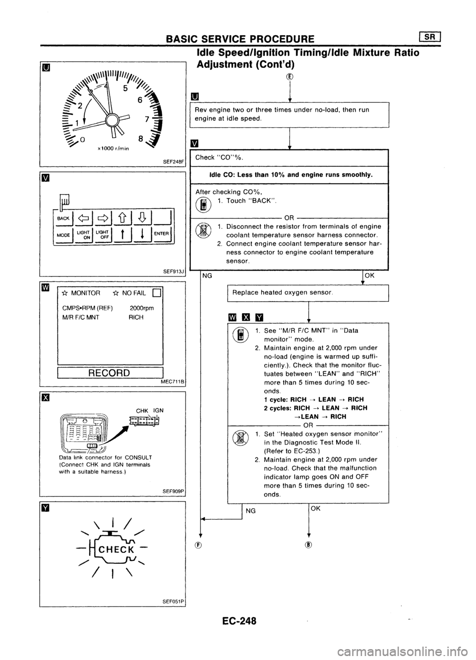
Rev engine twoorthree times under no-load, thenrun
engine atidle speed.
m
Check "CO"%.
Idle CO: Less than10%andengine runssmoothly.
After checking CO%.
00
1.
Touch "BACK".
OR
(j)
1.
Disconnect theresistor fromterminals ofengine
coolant temperature sensorharness connector.
2. Connect
enginecoolant temperature sensorhar-
ness connector toengine coolant temperature
sensor.
NG
1
0K
Replace heatedoxygen sensor.
fa
an
00
1.
See
"MIR
FIC
MNT" in"Data
monitor" mode.
2. Maintain
engineat2,000 rpmunder
no-load (engine iswarmed upsuffi-
ciently.). Checkthatthemonitor fluc-
tuates between "LEAN"and"RICH"
more than5times during 10sec-
onds.
1 cycle: RICH-->LEAN -.RICH
2 cycles: RICH-->LEAN -->RICH
-->LEAN -->RICH
OR
(j)
1.
Set
"Heated oxygensensormonitor"
in the Diagnostic TestMode II.
(Refef'to EC-253)
2. Maintain
engineat2,000 rpmunder
no-load. Checkthatthemalfunction
indicator lampgoesONand OFF
more than5times during 10sec-
onds.
I
NG OK
SEF913J
I
MEC7118
2000rpm
RICH
*
NO FAIL
D
RECORD
SEF909PBASIC
SERVICE PROCEDURE
mJ
Idle Speed/Ignition Timing/ldleMixtureRatio
Adjustment (Cont'd)
CID
SEF248F
\ I/
.........
~/'
- CHECK-
/
.......
/ I\
CMPS.RPM
(REF)
MIR F/CMNT
*
MONITOR
~~~~:?_-~ .
w=jr
~~~~"v
-~
Data linkconnector forCONSULT
(Connect CHKandIGN terminals
with asuitable harness)
SEF051PEC-248
Page 986 of 1701
TROUBLEDIAGNOSIS -General Description
KEY POINTS
WHAT .....
Vehicle &engine model
WHEN
Date,Frequencies
WHERE Roadconditions
HOW Operatingconditions,
Weather conditions,
Symptoms
SEF907L
WORKSHEET SAMPLE Diagnostic
Worksheet
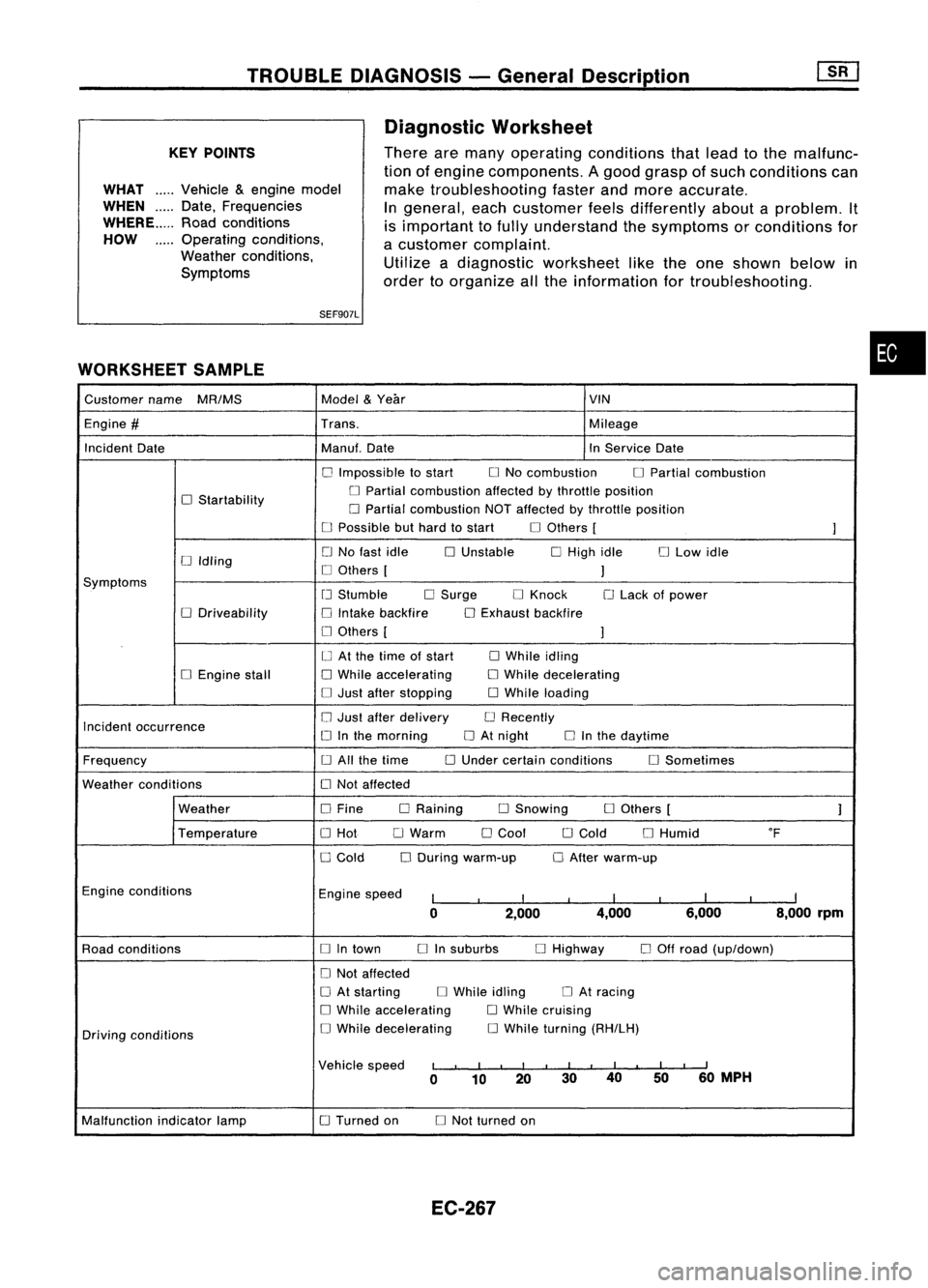
There aremany operating conditions thatlead tothe malfunc-
tion ofengine components. Agood grasp ofsuch conditions can
make troubleshooting fasterandmore accurate.
In
general, eachcustomer feelsdifferently aboutaproblem. It
is important tofully understand thesymptoms orconditions for
a customer complaint.
Utilize adiagnostic worksheet liketheone shown belowin
order toorganize allthe information fortroubleshooting.
•
Customer name
MR/MS Model
&
Year VIN
Engine
#
Trans. Mileage
Incident Date Manuf.Date InService Date
o
Impossible tostart
o
No combustion
o
Partial combustion
o
Startability
o
Partial combustion affectedbythrottle position
o
Partial combustion NOTaffected bythrottle position
o
Possible buthard tostart
o
Others [
]
o
No fast idle
o
Unstable
o
High idle
o
Low idle
[J
Idling
o
Others [
]
Symptoms
[J
Stumble
o
Surge
o
Knock
o
Lack ofpower
o
Driveability
o
Intake backfire
o
Exhaust backfire
o
Others [
]
o
At the time ofstart
o
While idling
o
Engine stall
o
While accelerating
o
While decelerating
o
Just after stopping
o
While loading
Incident occurrence
o
Just after delivery
o
Recently
o
Inthe morning
o
At night
o
Inthe daytime
Frequency
o
All the time
o
Under certain conditions
o
Sometimes
Weather conditions
o
Not affected
Weather
o
Fine DRaining
o
Snowing
o
Others [
]
Temperature
o
Hot
o
Warm
o
Cool
o
Cold
o
Humid
of
o
Cold
o
During warm-up
o
After warm-up
Engine conditions
Enginespeed
I
I
I
I
I
I
I
I
I
0 2,000 4,000
6,000 8,000rpm
Road conditions
o
Intown
o
Insuburbs
o
Highway
o
Off road (up/down)
o
Not affected
o
At starting
o
While idling
o
At racing
o
While accelerating
o
While cruising
Driving conditions
o
While decelerating
o
While turning (RH/LH)
Vehicle speed
I
I
I
I
I
I
II
I
I
I
II
0 10 20 3040
5060
MPH
Malfunction indicatorlamp
o
Turned on
o
Not turned on
EC-267
Page 1339 of 1701
SERVICEOATAAND SPECIFICATIONS (SOS)
Inspection andAdjustment (Cont'd)
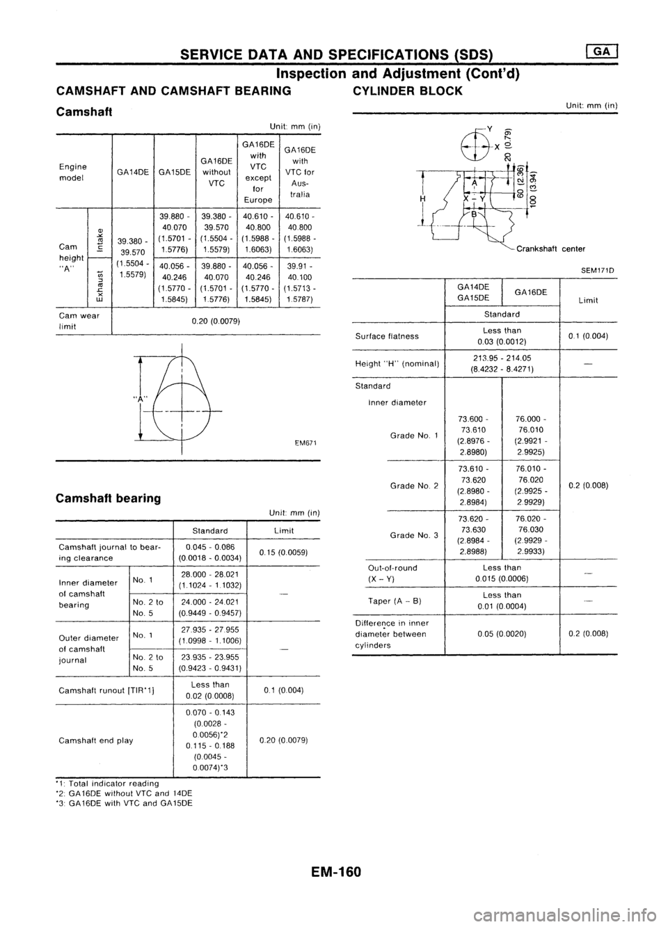
CAMSHAFT ANDCAMSHAFT BEARING CYLINDERBLOCK
Camshaft
Unit:
mm(in)
Unit: mm(in)
GA16DE GA16DE
GA16DE with
with
Engine GA14DEGA15DE without
VTC
VTC
for
model
VTC
except
Aus-
for tralia
Europe
39,880 -
39,380 -40,610
-
40,610 -
Q)
40070
39,570
40,800
40800
""
(1.5701
-(1.5504 -(1.5988 -(1.5988 -
<1l
39,380 -
Cam
C
1.5776)1.5579)1.6063) 1.6063)
39.570
height
-
"A" (1,5504
-
40.056 -39.880 -
40.056 -39.91
-
U;
1.5579)
40.24640,07040.246 40.100
:::l
<1l
(1.5770-(1.5701-(1.5770 -(1.5713 -
.c
x
1,5845)1,5776)
1.5845) 1,5787)
w
Cam wear
0.20(0.0079)
limit
EM671
Camshaft bearing
Unit:mm(in)
Standard Limit
Camshaft journaltobear- 0,045
-0.086
0,15(0.0059)
ing clearance (00018-0.0034)
NO.1 28.000
-28,021
Inner diameter
(1.1024-1 1032)
of camshaft
-
bearing No.
2to 24,000
-24021
No, 5 (0.9449
-0.9457)
NO.1 27.935
-27.955
Outer diameter
(1,0998-1.1006)
of camshaft
.-
journal No.
2to 23935
-23.955
No, 5 (0,9423
-0,9431)
Camshaft runout[TIR'1] Less
than
01(0,004)
0.02 (0.0008)
0070 -0 143
(0,0028 -
Camshaft endplay 0.0056)'2
020(0,0079)
0,115 -0,188
(0.0045 -
0.0074)'3
T
1
Crankshaftcenter
SEM171D
GA14DE GA16DE
GA15DE Limit
Standard
Surface flatness Less
than
0,1(0,004)
0,03 (0.0012)
Height "H"(nominal) 213.95
-214.05
-
(8.4232 -8.4271)
Standard Inner diameter
73.600- 76.000-
Grade No.1 73,610
76,010
(2.8976 -(2,9921
-
2.8980) 2.9925)
73.610 - 76.010
-
Grade NO.2 73,620
76020
0.2(0,008)
(2.8980 -(2.9925
-
2.8984) 2.9929)
73,620 - 76.020-
Grade No.3 73.630
76.030
(2,8984 -(2.9929 -
2.8988) 2,9933)
Out-ot-round Less
than
-
(X -Yi
0,015
(0.0006)
Less than
Taper (A-B)
._-
0.01 (0.0004)
Difference ininner
diameter between 005
(0,0020) 0,2
(0.008)
cylinders
'1: Total indicator reading
'2: GA 16DE without
VTC
and 14DE
'3: GA16DE withVTC andGA15DE
EM-160
Page 1341 of 1701
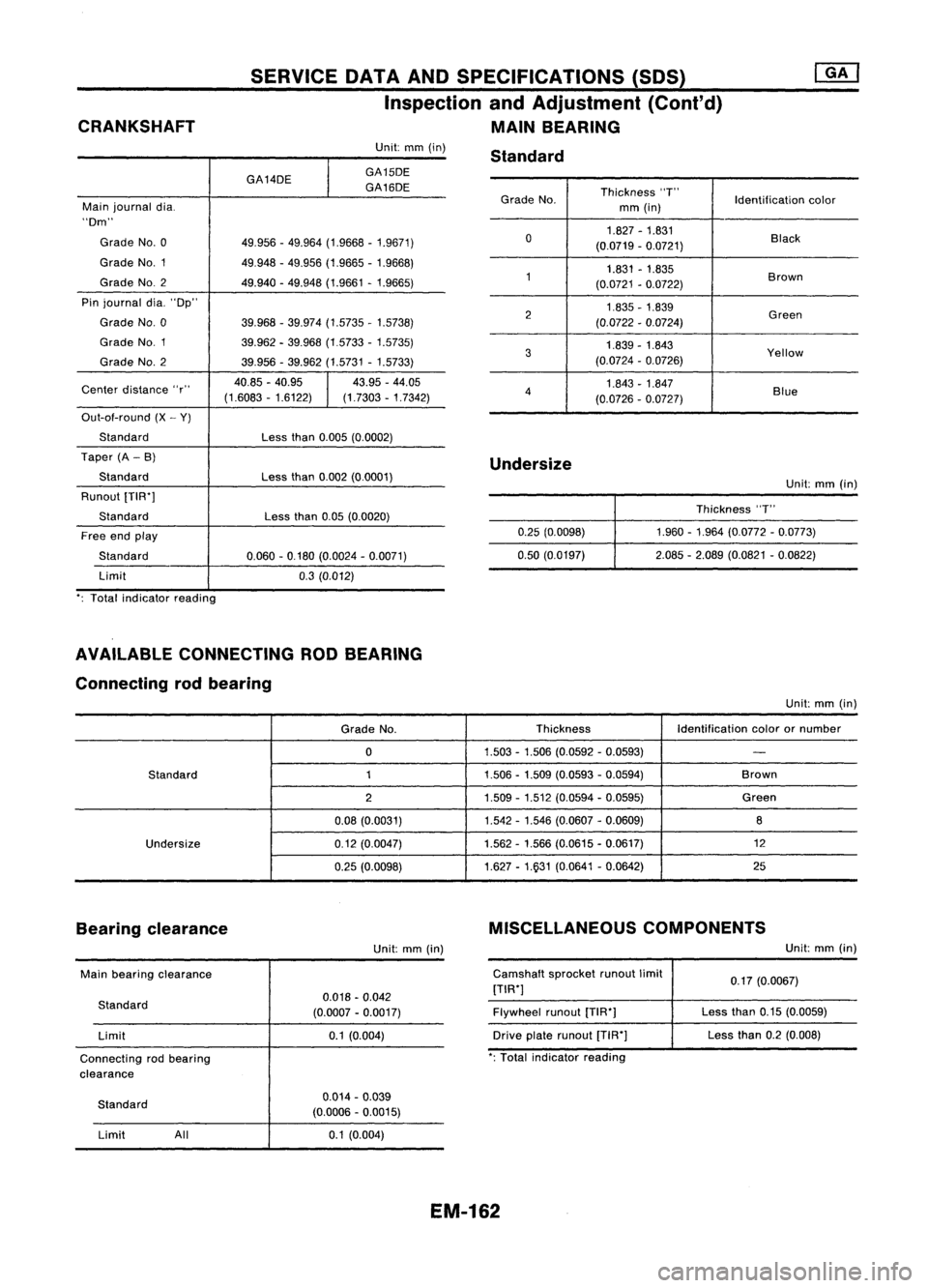
CRANKSHAFT SERVICE
DATAANDSPECIFICATIONS (SOS)
Inspection andAdjustment (Cont'd)
MAIN BEARING
Grade No. Thickness
"T"
Identificationcolor
mm (in)
0 1.827
-1.831
Black
(0.0719 -0.0721)
1 1.831
-1.835
Brown
(0.0721 -0.0722)
2 1.835
-1.839
Green
(0.0722 -0.0724)
3 1.839
-1.843
Yellow
(0.0724 -0.0726)
4 1.843
-1.847
Blue
(0.0726 -0.0727)
Unit:
mm(in)
GA14DE
I
GA15DE
GA16DE
Main journal dia.
"Dm"
Grade No.0 49.956-49.964 (1.9668 -1.9671)
Grade NO.1 49.948-49.956 (1.9665 -1.9668)
Grade NO.2
49.940-49.948 (1.9661 -1.9665)
Pin journal dia."Dp"
Grade No.0 39.968-39.974 (1.5735 -1.5738)
Grade NO.1
39.962-39.968 (1.5733 -1.5735)
Grade No.2 39.956-39.962 (1.5731 -1.5733)
Center distance "r" 40.85
-40.95
I
43.95
-44.05
(1.6083 -1.6122) (1.7303-1.7342)
Out-ot-round (X-Y)
Standard Lessthan0.005 (0.0002)
Taper (A-B)
Standard Lessthan0.002 (0.0001)
Runout [TIW]
Standard Lessthan0.05(0.0020)
Free endplay
Standard 0.060-0.180 (0.0024 -0.0071)
Limit 0.3(0.012)
': Total indicator reading Standard
Undersize 0.25(0.0098)
0.50 (0.0197) Unit:
mm(in)
Thickness "T"
1.960 -1.964 (0.0772 -0.0773)
2.085 -2.089 (0.0821 -0.0822)
AVAILABLE CONNECTING RODBEARING
Connecting rodbearing
Unit:mm(in)
Grade No. Thickness
Identificationcolorornumber
0 1.503
-1.506 (0.0592 -0.0593)
-
Standard 11.506-1.509 (0.0593 -0.0594) Brown
2 1.509
-1.512 (0.0594 -0.0595) Green
0.08 (0.0031) 1.542
-1.546 (0.0607 -0.0609)
8
Undersize 0.12(0.0047) 1.562
-1.566 (0.0615 -0.0617) 12
0.25 (0.0098) 1.627
-1.931 (0.0641 -0.0642) 25
Bearing clearance
Unit:mm(in) MISCELLANEOUS
COMPONENTS
Unit:mm(in)
Main bearing clearance
Standard Limit
Connecting rodbearing
clearance 0.018
-0.042
(0.0007 -0.0017)
0.1 (0.004) Camshaft
sprocketrunoutlimit
[TIW]
Flywheel runout[TIW]
Drive platerunout [T1R']
': Total indicator reading 0.17
(0.0067)
Less than0.15(0.0059)
Less than0.2(0.008)
Standard Limit All 0.014
-0.039
(0.0006 -0.0015)
0.1 (0.004)
EM-162
Page 1346 of 1701
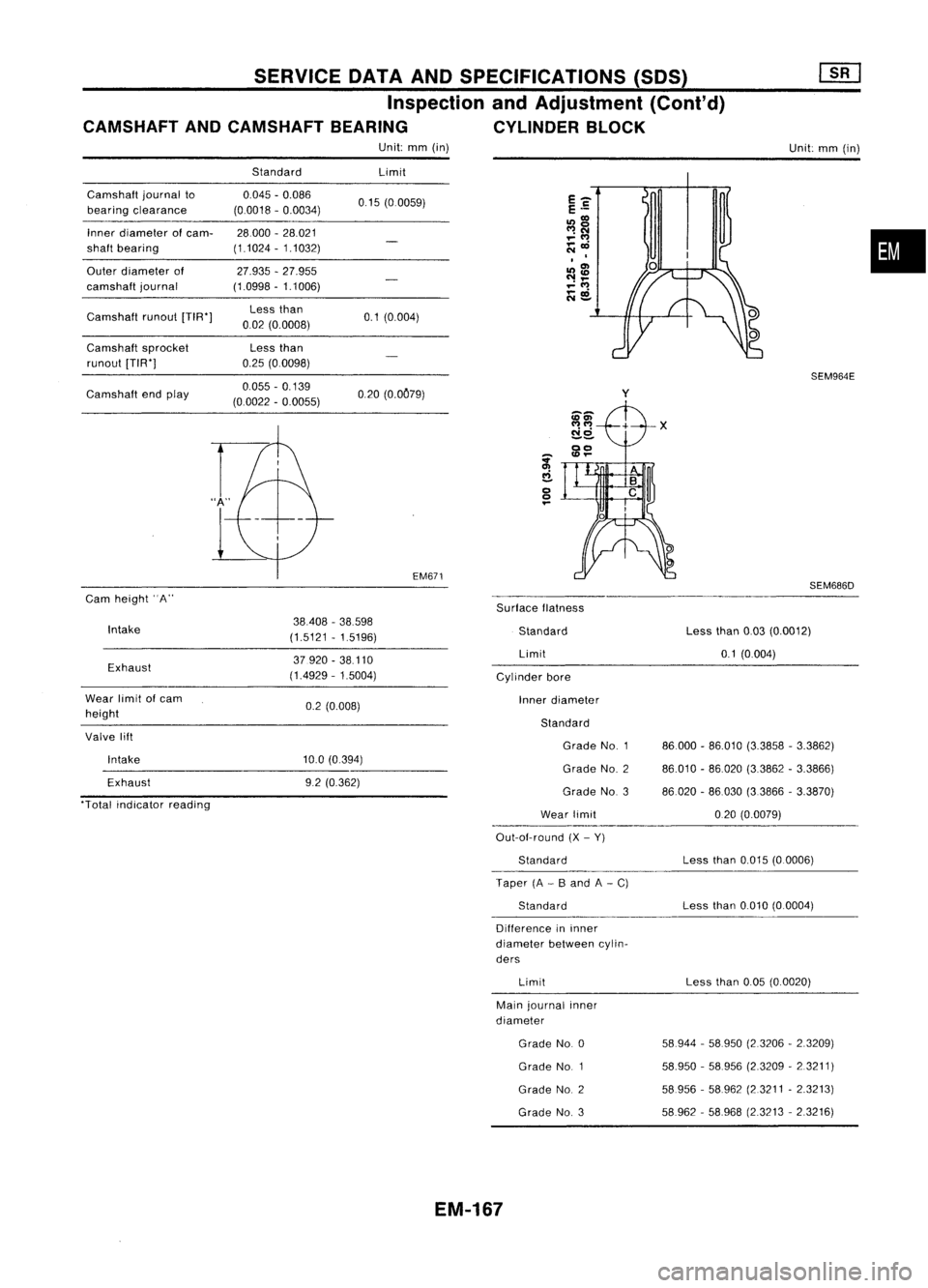
SERVICEDATAANDSPECIFICATIONS (SOS)
Inspection andAdjustment (Cont'd)
CAMSHAFT ANDCAMSHAFT BEARING CYLINDERBLOCK
Unit: mm(in)
Unit:mm(in)
Camshaft journalto
bearing clearance
Inner diameter
01
cam-
shaft bearing
Outer diameter of
camshaft journal
Camshaft runout[TIW]
Camshaft sprocket
runout [TIW]
Camshaft endplay
Cam height
"A"
Standard
0.045 -0.086
(0.0018 -0.0034)
28000 -28.021
(1.1024 -1.1032)
27.935 -27.955
(1.0998 -1.1006)
Less than
002 (0.0008)
Less than
0.25 (00098)
0.055 -0.139
(0.0022 -0.0055) Limit
0.15 (00059)
0.1 (0.004)
020 (0.OC79)
EM6?1
SurfaceIlatness
y
SEM964E
SEM686D
•
Intake
Exhaust
Wear limit
01
cam
height
Valve lift
Intake
Exhaust
"Total indicator reading 38408
-38.598
(1.5121 -1.5196)
37.920 -38.110
(14929 -1.5004)
0.2 (0.008)
10.0 (0.394)
9.2 (0.362) Standard
Limit
Cylinder bore
Inner diameter
Standard Grade No.1
Grade NO.2
Grade No.3
Wear limit
Out-aI-round (X-Y)
Standard
Taper (A-B and A-C)
Standard
Difference ininner
diameter betweencylin-
ders
Limit
Main journal inner
diameter
Grade No.0
Grade NO.1
Grade NO.2
Grade NO.3
EM-167
Less
than0.03(0.0012)
0.1 (0004)
86.000 -86.010 (3.3858 -3.3862)
86.010 -86020 (3.3862 -3.3866)
86020 -86.030 (33866 -3.3870)
020 (0.0079)
Less than0.015 (0.0006)
Less than0.010 (0.0004)
Less than0.05(0.0020)
58944 -58950 (2.3206 -2.3209)
58.950 -58.956 (2.3209 -2.3211)
58956 -58962 (2.3211 -2.3213)
58962 -58968 (23213 -2.3216)
Page 1354 of 1701
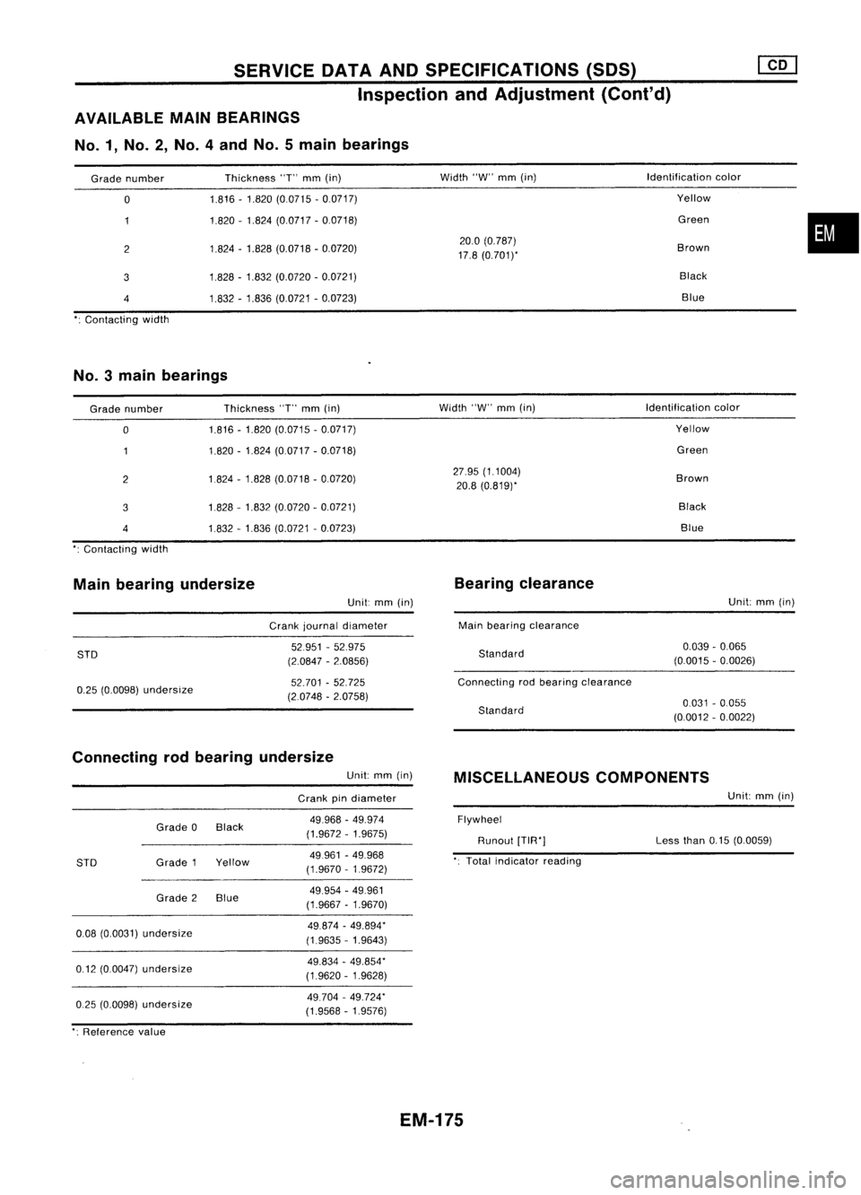
SERVICEOATAAND SPECIFICATIONS (SOS)
Inspection andAdjustment (Cont'd)
AVAILABLE MAINBEARINGS
No.1, No.2, No.4andNo.5main bearings
Grade number
o
2
3
4
Contacting width Thickness
"T"
mm
(in)
1.816 -1.820 (0.0715 -0.0717)
1.820 -1.824 (0.0717 -0.0718)
1.824 -1.828 (0.0718 -0.0720)
1.828 -1.832 (0.0720 -0.0721)
1.832 -1.836 (0.0721 -0.0723)
Width
"W"
mm
(in)
20.0 (0.787)
17.8 (0.7011'
Identification
color
Yellow
Green
Brown Black Blue
•
No.3 mainbearings
Grade number
o
2
3
4
Contacting width Thickness
"T"
mm
(in)
1.816 -1.820 (0.0715 -0.0717)
1.820 -1.824 (0.0717 -0.0718)
1.824 -1.828 (0.0718 -0.0720)
1828 -1.832 (0.0720 -0.0721)
1.832 -1.836 (0.0721 -0.0723)
Width
"W"
mm
(in)
27.95 (1.1004)
20.8 (0.819)'
Identification
color
Yellow
Green
Brown BlackBlue
Main bearing undersize
Unit:
mm
(in)
Crank journal diameter
Bearing
clearance
Main bearing clearance Unit:
mm
(in)
STD
0.25 (0.0098)
undersize
52951
-52.975
(2.0847 -2.0856)
52.701 -52.725
(2.0748 -2.0758)
Standard
Connecting rodbearing clearance
Standard
0.039
-0.065
(0.0015 -0.0026)
0.031 -0.055
(0.0012 -0.0022)
Connecting rodbearing undersize
Unit:
mm
(in)
Crank pindiameter
MISCELLANEOUS
COMPONENTS
Unit:
mm
(in)
0.25 (0.0098)
undersize
0.08
(0.0031)
undersize
0.12 (0.0047)
undersize
STD
Grade
0Black
Grade 1Yellow
Grade 2Blue
49.968
-49.974
(1.9672 -1.9675)
49961 -49.968
(1.9670 -1.9672)
49.954 -49.961
(1.9667 -1.9670)
49.874 -49.894"
(1.9635 -1.9643)
49.834 -49.854"
(1.9620 -1.9628)
49.704 -49.724"
(1.9568 -1.9576)
Flywheel
Runout
[TIR"]
Total indicator reading Less
than
0.15(0.0059)
": Reference value
EM-175
Page 1357 of 1701
SGI916PRECAUTIONS
• Donot use electrical testequipment onany circuit related •
to the SRS unless instructed tointhis Service Manual.
Precautions forNATS V2.0(ForGasoline Engine
Model)
NATS (Nissan Anti-Theft System)
NATS V2.0willimmobilize theengine ifsomeone triestostart
it without theregistered keyofNATS V2.0.
Both ofthe originally suppliedignitionkeyIDshave been NATS
registered.
The NATS security indicator islocated onthe instrument panel.
The indicator blinkswhentheignition switchisin "OFF" or
"ACC" position. Therefore, NATSwarns outsiders thatthevehi-
cle isequipped withtheanti-theft system.
• When NATSdetects trouble, themalfunction indicatorlamp
(MIL) blinks.
This blinking indicates thattheanti-theft isnot functioning,
so prompt service isrequired.
• When servicing NATS(trouble diagnoses, systeminitialisa-
tion andadditional registration ofother NATS ignition key
IDs), CONSULT hardwareandCONSULT NATSsoftware is
necessary.
Regarding theprocedures ofNATS initialisation andNATS
ignition key
10
registration, refertoCONSULT operation
manual, NATSV2.0.
Therefore, CONSULTNATSsoftware (program cardandoper-
ation manual) mustbekept strictly confidential tomaintain the
integrity ofthe anti-theft function.
• When servicing NATSV2.0(trouble diagnoses, systemini-
tial isation andadditional registration ofother NATS ignition
key IDs),
it
may benecessary tore-register originalkey
identification. Therefore,besure toreceive allkeys from
vehicle owner.
A maximum offour keyIDscan beregistered intoNATS.
• When failing tostart theengine first-time usingthekey of
NATS V2.0,startasfollows.
(1) Turn ignition keyto"OFF".
(2) Wait approx. 5seconds.
(3) Turn ignition keyto"START" againwhilekeeping the
key apart fromanyothers onkey-chain.
SGI285 General
Precautions
• Donot operate theengine foranextended periodoftime
without properexhaust ventilation.
Keep thework areawellventilated andfree ofany flamma-
ble materials. Specialcareshould betaken whenhandling
any flammable orpoisonous materials,suchasgasoline,
refrigerant gas,etc.When working inapit orother enclosed
area, besure toproperly ventilate thearea before working
with hazardous materials.
Do not smoke whileworking onthe vehicle.
GI-3
Page 1401 of 1701
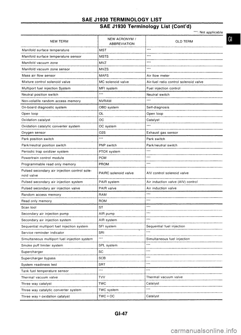
SAEJ1930 TERMINOLOGY LIST
SAE J1930 Terminology List(Cont'd)
NEW TERM NEW
ACRONYM /
OLDTERM
ABBREVIATION
Manifold surfacetemperature MST
...
Manifold surfacetemperature sensor MSTS
...
Manifold vacuumzone MVZ
...
Manifold vacuumzonesensor MVZS
...
Mass airflow sensor
MAFSAirflow meter
Mixture controlsolenoid valve
MCsolenoid valve Air-fuelratiocontrol solenoid valve
Multipart fuelinjection System MFIsystem Fuelinjection control
Neutral position switch
...
Neutralswitch
Non-volatile randomaccessmemory
NVRAM
...
On-board diagnostic system OBOsystem Self-diagnosis
Open loop
OLOpen
loop
Oxidation catalyst
OCCatalyst
Oxidation catalyticconverter system OCsystem
...
Oxygen sensor
02SExhaust
gassensor
Park position switch
...
Parkswitch
Park/neutral positionswitch
PNPswitch Park/neutralswitch
Periodic trapoxidizer system
PTOXsystem
...
Powertrain controlmodule PCM
...
Programmable readonlymemory PROM
...
Pulsed secondary airinjection controlsole-
PAIRCsolenoid valve AIV
control solenoid valve
noid valve
Pulsed secondary airinjection system PAIRsystem Air
induction valve(AIV)control
Pulsed secondary airinjection valve PAIR
valve Airinduction valve
Random accessmemory RAM
...
Read onlymemory ROM
...
Scan tool ST
...
Secondary airinjection pump AIRpump
...
Secondary airinjection system AIR
system
...
Sequential multiportfuelinjection system SFI
system Sequentialfuelinjection
.
Service reminder indicator SRI
...
Simultaneous multipartfuelinjection system
...
Simultaneousfuelinjection
Smoke pufflimiter system SPL
system
...
Supercharger SC
...
Supercharger bypass 5CB
...
System readiness test 5RT
...
Tank fueltemperature sensor
...
...
Thermal vacuumvalve TVV
Thermal
vacuumvalve
Three waycatalyst TWC
Catalyst
Three waycatalytic converter system TWC
system
...
Three way+oxidation catalyst TWC+OC Catalyst
GI-47