1995 NISSAN ALMERA N15 service indicator
[x] Cancel search: service indicatorPage 756 of 1701
SEF217M
•
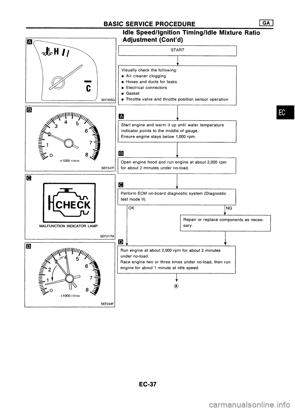
START
Visually checkthefollowing:
• Air cleaner clogging
• Hoses andducts forleaks
• Electrical connectors
• Gasket
• Throttle valveandthrottle position sensoroperation
m
Start engine andwarm itup until water temperature
indicator pointstothe middle ofgauge.
Ensure enginestaysbelow 1,000rpm.
iii
Open engine hoodandrunengine atabout 2,000rpm
for about 2minutes underno-load.
[iJ
Perform ECMon-board diagnostic system(Diagnostic
test mode II).
OK lNG
Repair orreplace components asneces-
sary.
I!]
1
Run engine atabout 2,000rpmforabout 2minutes
under no-load.
Race engine twoorthree times under no-load, thenrun
engine forabout 1minute atidle speed.
~
BASIC
SERVICE PROCEDURE
eM]
Idle Speed/Ignition Timing/IdleMixtureRatio
Adjustment (Cont'd)
SEF247F
SEF455Q
MALFUNCTION INDICATORLAMP
SEF248F
EC-37
Page 759 of 1701
o
1:<
MONITOR
1<
NO FAIL
0
BASIC
SERVICE PROCEDURE
@KJ
Idle Speedllgnition Timing/IdleMixtureRatio
Adjustment (Cont'd)
@
CMPS.RPM (REF)
MIR
F/C
MNT 2000rpm
RICH
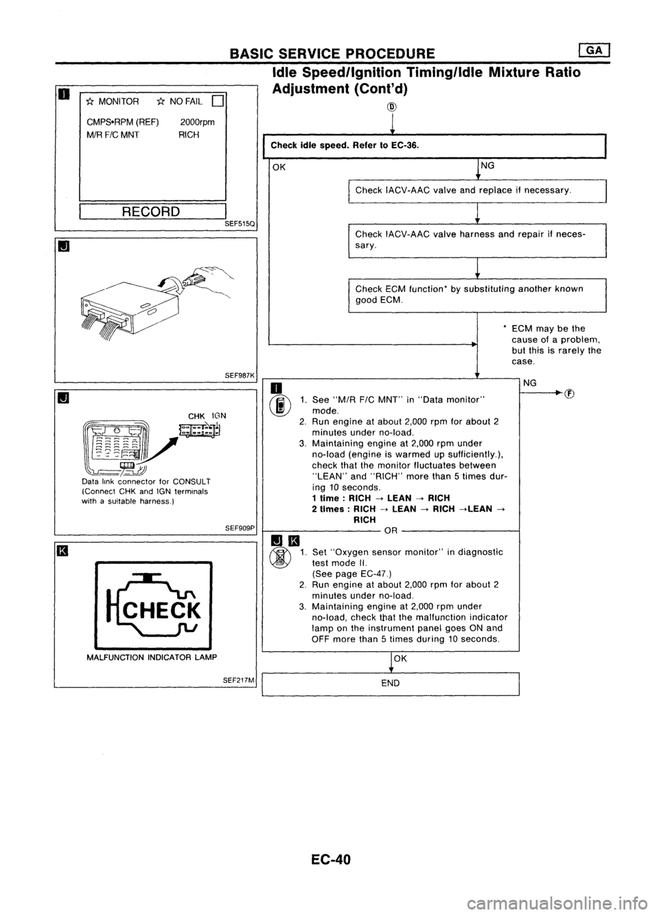
Checkidlespeed. Refer10EC-36.
OK NG
Check IACV-AAC valveandreplace ifnecessary.
__ R_E_C_O_R_D __
I
SEF515Q
CheckIACV-AAC valveharness andrepair ifneces-
sary.
Check ECMfunction- bysubstituting anotherknown
good ECM.
-ECM maybethe
cause ofaproblem,
but this israrely the
case.
SEF987K
(g~~~:: _
mJ
~~r
l~~~~V
-~
Data linkconnector forCONSULT
(Connect CHKandIGN terminals
with asuitable harness.)
SEF909P
MALFUNCTION INDICATORLAMP
SEF217M
o
(ij\E
1.See "MIA
F/C
MNT" in"Data monitor"
~ mode.
2. Run engine atabout 2,000rpmforabout 2
minutes underno-load.
3. Maintaining engineat2,000 rpmunder
no-load (engine iswarmed upsufficiently.),
check thatthemonitor fluctuates between
"LEAN" and"RICH" morethan5times dur-
ing 10seconds.
1 lime: RICH->LEAN ->RICH
2 limes: RICH->LEAN
->
RICH ->LEAN
->
RICH OR
Set "Oxygen sensormonitor" indiagnostic
test mode II.
(See page EC-47.)
2. Run engine atabout 2,000rpmforabout 2
minutes underno-load.
3. Maintaining engineat2,000 rpmunder
no-load, checkthatthemalfunction indicator
lamp onthe instrument panelgoesONand
OFF more than5times during 10seconds.
OK
END
EC-40 NG
Page 760 of 1701
•
oxygen
sen-
Europe and
nd Australia
els)
sensor
for Europe
el, and Aus-
T models)
@
II
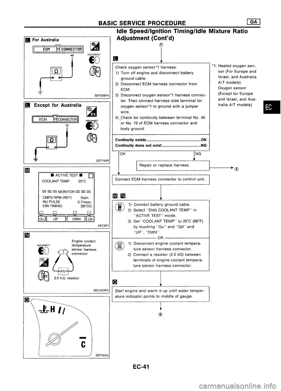
Check oxygen sensor*1 harness: *1:
Heated
1) Turn offengine anddisconnect battery sor
(For
ground cable. Israel,
a
2) Disconnect ECMharness connector from
AIT
mod
ECM. Oxygen
3) Disconnect oxygensensor*1 harnessconnec- (Except
tor. Then connect harness sideterminal for and
Isra
oxygen sensor*1 toground withajumper tralia
AI
wire.
4) .Check forcontinuity betweenterminalNo.46
or No. 19ofECM harness connector and
body ground.
Continuity exists................................................ OK
Continuity doesnotexist .................................. NG
OK lNG
I
Repair orreplace harness.
Connect ECMharness connector tocontrol unit.
~
III
00
1)
Connect batteryground cable.
2) Select "ENGCOOLANT TEMP"in
"ACTIVE TEST"mode.
3) Set "COOLANT TEMP"to20°C (68°F)
by touching "au"and"ad" and
"UP", "DWN".
OR
@
1)
Disconnect enginecoolant tempera-
ture sensor harness connector.
2) Connect aresistor (2.5kQ)between
terminals ofengine coolant tempera-
ture sensor harness connector.
[+]
Start engine andwarm itup until water temper-
ature indicator pointstomiddle ofgauge.
~
BASIC
SERVICE PROCEDURE ~
Idle Speed/Ignition Timing/IdleMixtureRatio
Adjustment (Cont'd)
CD
SEF194R
SEF056PA
~
DISCONNECT
18
~
AEC681
===MONITOR===
CMPS.RPM (REF)
Orpm
INJ PULSE
O.7msec
IGN TIMING 5BTDC
SEC242BA
•
ACTIVE TEST.
0
COOLANT TEMP 20°C
Engine coolant
DISCONNECT
temperature
10
!;j:~:~~'~";"'"
~
00
2.5k
n
resistor
II
ECM
19'
CONNECTOR
II
19
II
For Australia
II
ECM ~CONNECTORII
46
II
Except forAustralia
SEF455Q EC-41
Page 761 of 1701
@@
'1: Heated oxygen sensor(ForEurope
and Israel, andAustralia AITmod-
els) Oxygen sensor(Except forEurope
and Israel, andAustralia AITmod-
els)
Ii
1
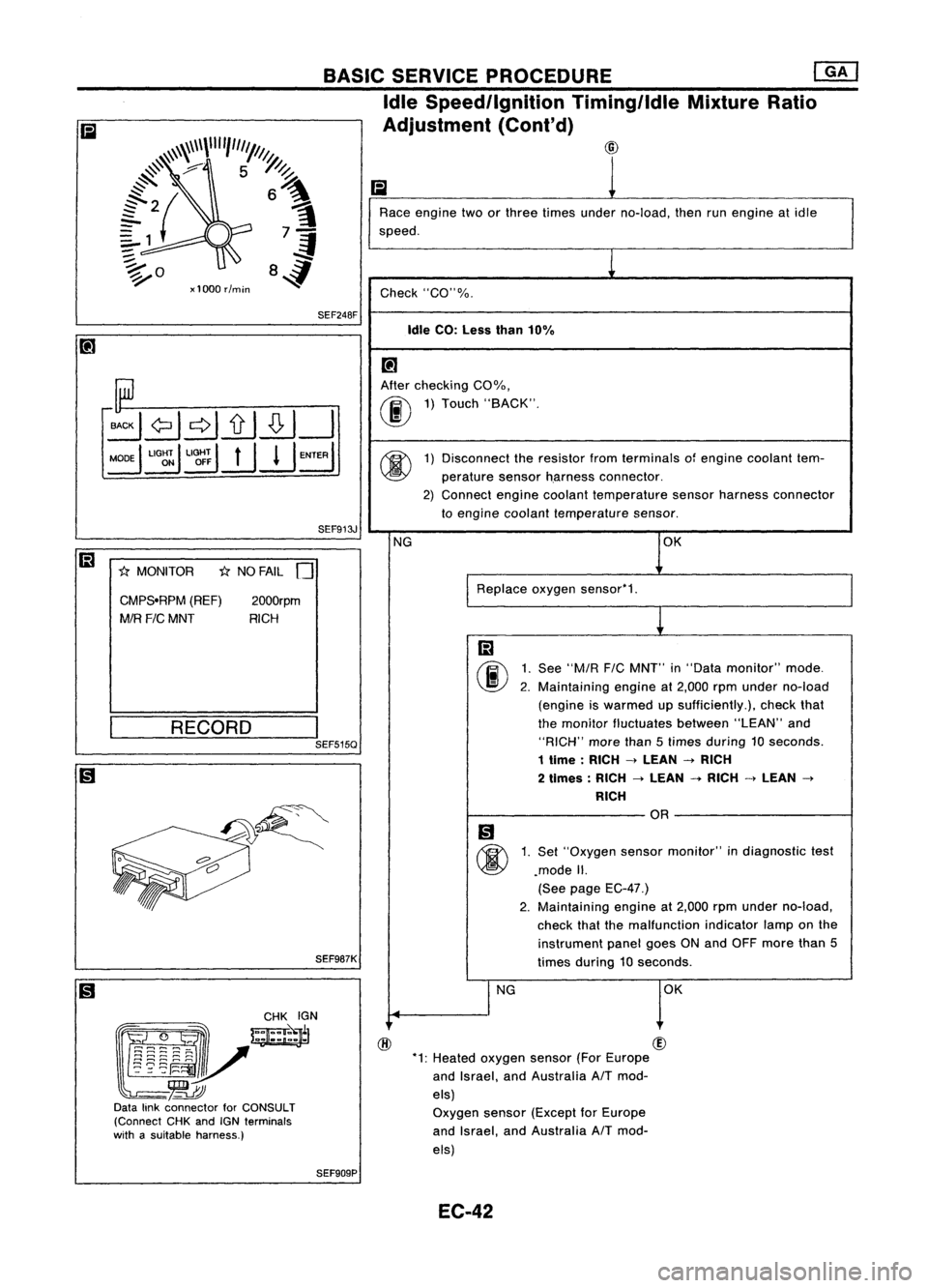
Race engine twoorthree times under no-load, thenrunengine atidle
speed.
1
Check "CO"%.
Idle CO:Less than10%
[!J
After checking COOJo,
00
1)
Touch "BACK".
@
1)
Disconnect theresistor fromterminals ofengine coolant tem-
perature sensorh.arness connector.
2) Connect enginecoolant temperature sensorharness connector
to engine coolant temperature sensor.
NG OK
Replace oxygensensor'1.
m
00
1.
See
"M/R
FIC
MNT" in"Data monitor" mode.
2. Maintaining engineat2,000 rpmunder no-load
(engine iswarmed upsufficiently.), checkthat
the monitor fluctuates between"LEAN"and
"RICH" morethan5times during 10seconds.
1 time :RICH
->
LEAN
->
RICH
2 times: RICH
->
LEAN
-+
RICH
->
LEAN
->
RICH
OR
Ii)
@
1.
Set "Oxygen sensormonitor" indiagnostic test
.mode II.
(See page EC-47.)
2. Maintaining
engineat2,000 rpmunder no-load,
check thatthemalfunction indicatorlamponthe
instrument panelgoesONand OFF more than5
times during 10seconds.
I
NG OK
SEF913J
2000rpm
RICH
1;:(
NO FAIL
0
SEF248F
CMPS.RPM (REF)
MIR
FIC
MNT
1;:(
MONITOR
BASIC
SERVICE PROCEDURE ~
Idle Speed/Ignition TiminglldleMixtureRatio
Adjustment (Cont'd)
~\\~\\\\""1"'1///1.
@
#'
7 5~
~ ~
{2{ 6~
?1 7-=1
:;::. .;f
~o 84
xl000 rlmin
SEF987K
(gJ~
~~~~N
l~~i~V-=~
-~
Data linkconnector forCONSULT
(Connect CHKandIGNterminals
with asuitable harness.)
__
R_E_C_O_R_D __
I
SEF515Q
SEF909P EC-42
Page 780 of 1701
TROUBLEDIAGNOSIS -General Description
KEY POINTS
WHAT .....Vehicle &engine model
WHEN Date,Frequencies
WHERE Roadconditions
HOW Operatingconditions,
Weather conditions,
Symptoms
SEF907L
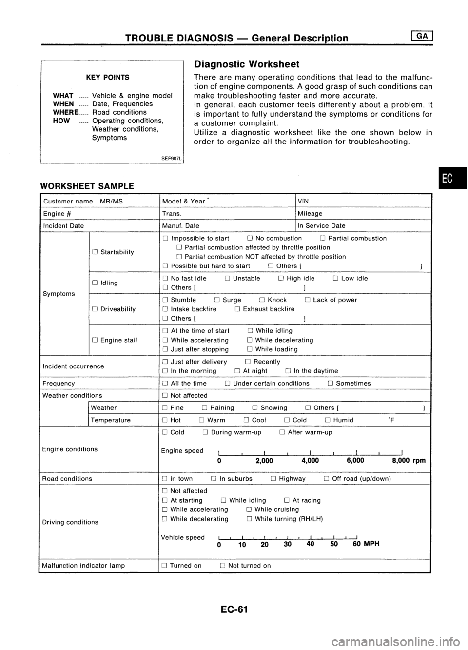
WORKSHEET SAMPLE
Diagnostic
Worksheet
There aremany operating conditions thatlead tothe malfunc-
tion ofengine components. Agood grasp ofsuch conditions can
make troubleshooting fasterandmore accurate.
In general, eachcustomer feelsdifferently aboutaproblem. It
is important tofully understand thesymptoms orconditions for
a customer complaint.
Utilize adiagnostic worksheet liketheone shown belowin
order toorganize allthe information fortroubleshooting.
•
Customer name
MR/MS Model
&
Year
.
VIN
Engine
#
Trans. Mileage
Incident Date Manu!.Date InService Date
o
Impossible tostart
o
No combustion
o
Partial combustion
o
Startability
o
Partial combustion affectedbythrottle position
LJ Partial combustion NOTaffected bythrottle position
o
Possible buthard tostart
o
Others [
1
o
Idling
o
No fast idle
o
Unstable
o
High idle
o
Low idle
o
Others [
1
Symptoms
o
Stumble
o
Surge
o
Knock
o
Lack ofpower
o
Driveability
i.J
Intake backfire
o
Exhaust backfire
o
Others [
1
o
At the lime ofstart
o
While idling
[.J
Engine stall
o
While accelerating
o
While decelerating
o
Just after stopping
o
While loading
Incident occurrence
o
Just after delivery
o
Recently
o
Inthe morning
o
At night
o
Inthe daytime
Frequency
o
All the time
o
Under certain conditions
o
Sometimes
Weather conditions
o
Not affected
Weather
o
Fine DRaining
o
Snowing
o
Others [
1
Temperature
o
Hot
o
Warm
o
Cool
o
Cold
o
Humid OF
o
Cold
o
During warm-up
o
After warm-up
Engine conditions
Enginespeed
I
I
I
I
I
I
I
I
I
0 2,000 4,000
6,000 8,000
rpm
Road conditions
o
Intown
o
Insuburbs
o
Highway
o
Off road (up/down)
o
Not affected
o
At starting
o
While idling
o
At racing
o
While accelerating
o
While cruising
Driving conditions
o
While decelerating
o
While turning (RH/LH)
Vehicle speed
I
,
I
I
I III
I
I
I
II
0 10 20 30
40
5060
MPH
Malfunction indicatorlamp
o
Turned on
o
Not turned on
EC-61
Page 963 of 1701
@
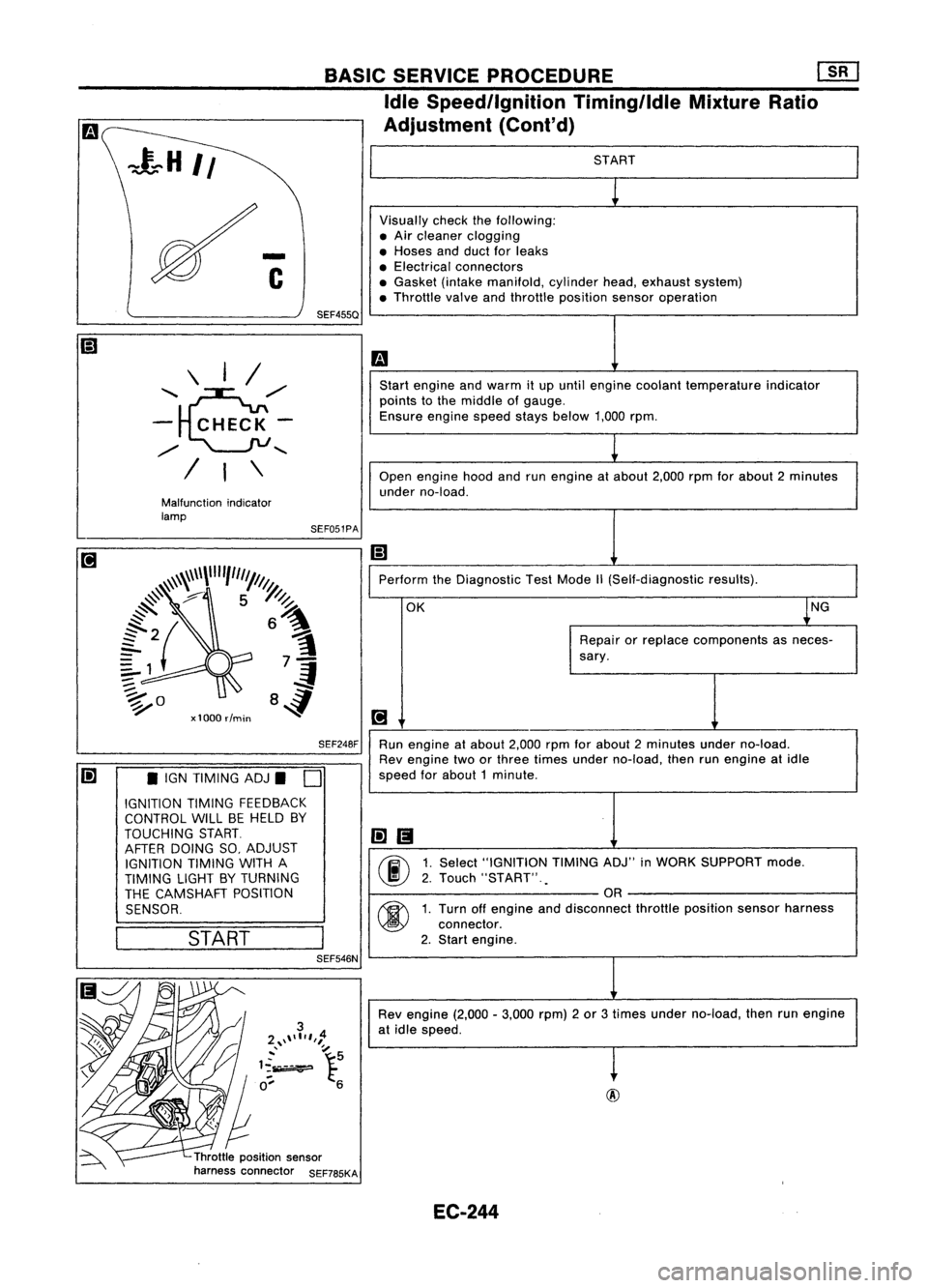
START
Visually checkthefollowing:
• Air cleaner clogging
• Hoses andduct forleaks
• Electrical connectors
• Gasket (intakemanifold, cylinderhead,exhaust system)
• Throttle valveandthrottle position sensoroperation
m
Start engine andwarm itup until engine coolant temperature indicator
points tothe middle ofgauge.
Ensure enginespeedstaysbelow 1,000rpm.
1
Open engine hoodandrunengine atabout 2,000rpmforabout 2minutes
under no-load.
Ii]
Perform theDiagnostic TestMode
1\
(Self-diagnostic results).
OK ~NG
Repair orreplace components asneces-
sary.
[!J
Run engine atabout 2,000rpmforabout 2minutes underno-load.
Rev engine twoorthree times under no-load, thenrunengine atidle
speed forabout 1minute .
li]1!I
00
1.
Select "IGNITION TIMINGADJ"inWORK SUPPORT mode.
2. Touch "START" .
.
OR
00
1.
Turn offengine anddisconnect throttleposition sensorharness
connector.
2. Start engine.
Rev engine (2,000-3,000 rpm)2or 3times under no-load, thenrunengine
at idle speed.
t
Throttle position sensor
harness connector SEF785KASEF051PA
BASIC
SERVICE PROCEDURE Em
Idle Speedllgnition TiminglldleMixtureRatio
Adjustment (Cont'd)
SEF248F
SEF455Q
Malfunction indicator
lamp \
I/
'~,,/
- CHECK-
,,/
........
/ I\
Ii] •IGN TIMING ADJ.
D
IGNITION TIMINGFEEDBACK
CONTROL WILLBEHELD BY
TOUCHING START.
AFTER DOING SO,ADJUST
IGNITION TIMINGWITHA
TIMING LIGHTBYTURNING
THE CAMSHAFT POSITION
SENSOR.
I
START
I
SEF546N
EC-244
Page 965 of 1701
BASICSERVICE PROCEDURE
mJ
Idle Speed/Ignition Timing/IdleMixtureRatio
Adjustment (Cont'd)
@
SEF909P SEF913J
RECORD
@
M
may bethe
se ofa
blem, butthis
arely thecase
II
1
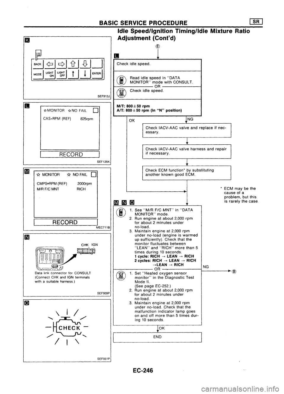
Check idlespeed.
00
Read
idlespeed in"DATA
MONITOR" modewithCONSULT.
OR
@
Check
idlespeed.
M/T:
800:l: 50rpm
A/T:
800:l: 50rpm (in
uN"
position)
OK ~NG
Check IACV-AAC valveandreplace ifnec-
essary.
~
Check IACV-AAC valveharness andrepair
if necessary.
~
Check ECMfunction- bysubstituting
another knowngoodECM.
-EC
cau
pro
1II111[!]
is
r
(j)
1.
See "M/R
FIC
MNT" in"DATA
MONITOR" mode.
2. Run engine atabout 2,000rpm
for about 2minutes under
no-load.
3.
Maintain engineat2,000 rpm
under no-load (engineiswarmed
up sufficiently). Checkthatthe
monitor fluctuates between
"LEAN" and"RICH" morethan5
times during 10seconds.
1 cycle: RICH->LEAN ->RICH
2 cycles: RICH->LEAN ->RICH
->LEAN ->RICH
NG
OR
~
(j)
1.
Set "Heated oxygensensor
monitor" inthe Diagnostic Test
Mode II.
(See page EC-252.)
2. Run
engine atabout 2,000rpm
for about 2minutes under
no-load.
3.
Maintain
engineat2,000 rpm
under no-load. Checkthatthe
malfunction indicatorlampgoes
on and offmore than5times dur-
ing 10seconds.
~OK
END
SEF135K
I
MEC7118
825rpm
2000rpm
RICH
1<
NO FAIL
D
RECORD
\ I/
.........
~/"
- CHECK-
/
......
/ I\
~MONITOR
~NOFAIL
0
CAS-RPM (REF)
CMPS.RPM (REF)
MIR
FIC
MNT
1<
MONITOR
@~~
~~r
~~V
-
-~
Data linkconnector forCONSULT
(Connect CHKandIGN terminals
with asuitable harness)
II
SEF051PEC-246
Page 966 of 1701
![NISSAN ALMERA N15 1995 Service Manual Heatedoxygen sensor
harness connector BASIC
SERVICE PROCEDURE [][]
Idle Speed/Ignition Timing/IdleMixtureRatio
Adjustment (Cont'd)
@
II
MEF031DB
~io
ECM TIcoNNECTORl1
19
LEn
MEC712B
Check
NISSAN ALMERA N15 1995 Service Manual Heatedoxygen sensor
harness connector BASIC
SERVICE PROCEDURE [][]
Idle Speed/Ignition Timing/IdleMixtureRatio
Adjustment (Cont'd)
@
II
MEF031DB
~io
ECM TIcoNNECTORl1
19
LEn
MEC712B
Check](/manual-img/5/57349/w960_57349-965.png)
Heatedoxygen sensor
harness connector BASIC
SERVICE PROCEDURE [][]
Idle Speed/Ignition Timing/IdleMixtureRatio
Adjustment (Cont'd)
@
II
MEF031DB
~io
ECM TIcoNNECTORl1
19
LEn
MEC712B
Check
heated oxygen sensorharness:
1. Turn offengine anddisconnect batteryground
cable.
2. Disconnect ECMharness connector fromECM.
3. Disconnect heatedoxygen sensorharness con-
nector. Thenconnect harness sideterminal for
heated oxygen sensortoground withajumper
wire.
4. Check forcontinuity betweenterminal
@
ofECM
harness connector andbody ground.
Continuity exists OK
Continuity doesnotexist NG
OK
Repairorreplace harness.
Connect ECMharness connector toECM .
•
OR
1.
Connect batteryground cable.
2. Select "ENGCOOLANT TEMP"in
"ACTIVE TEST"mode.
3. Set "COOLANT TEMP"to20"C (68"F) by
touching "Qu"and"Qd" and"UP",
"DWN".
Disconnect enginecoolant temperature
sensor harness connector.
2. Connect aresistor (2.5kQ)between termi-
nals ofengine coolant temperature sensor
harness connector.
3. Connect batteryground cable.
Ii
AEC681
•
ACTIVE TEST.
0
COOLANT TEMP 20°C
===MONITOR=== CMPS.RPM (REF)
Orpm
INJ PULSE
O.7msec
IGN TIMING 5BTDC
DISCONNFCT
Enginecoolant
10 temperature
sensor
harness connector
~ ~
00
2.5
k0 resistor
Start
engine andwarm itup until engine coolant
temperature indicatorpointstomiddle ofgauge.
(Be sure tostart engine aftersetting "COOLANT
'-- A_E_C6_8-l2
TEMP"orinstalling a2.5 kQresistor.)
Ii
SEF455QEC-247