1995 NISSAN ALMERA N15 service indicator
[x] Cancel search: service indicatorPage 171 of 1701
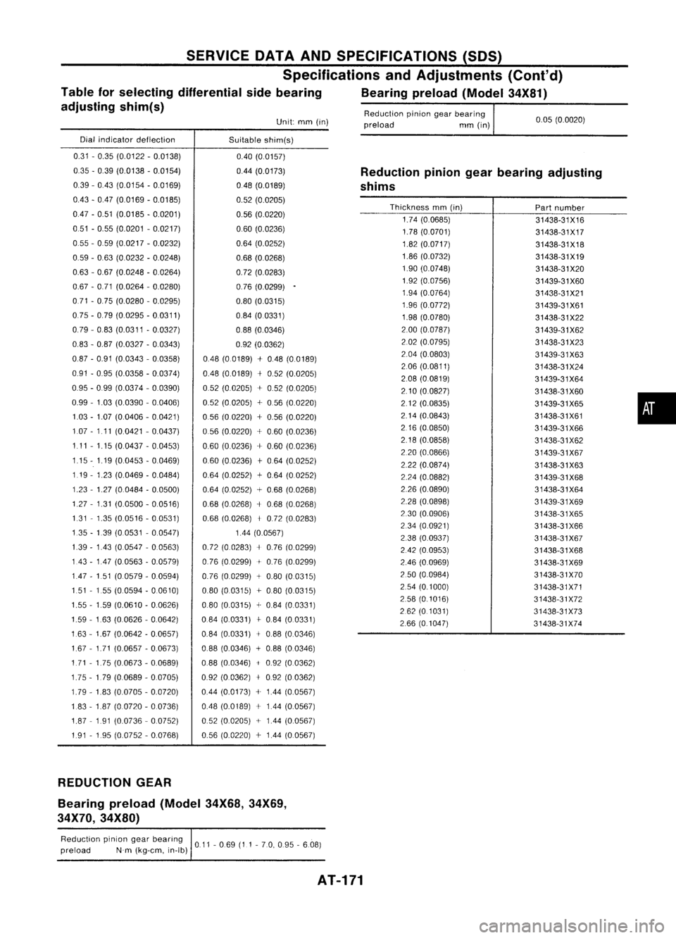
0.05(0.0020)
Reduction
piniongearbearing
preload mm(in)
Unit:
mm(in)
SERVICE
DATAANDSPECIFICATIONS (SOS)
Specifications andAdjustments (Cont'd)
Table forselecting differential sidebearing Bearingpreload(Model34X81)
adjusting shim(s)
Dial indicator deflection
Suitableshim(s)
Reductionpiniongearbearing adjusting
shims
0.31
-0.35 (0.0122 -0.0138)
035 -0.39 (0.0138 -0.0154)
0.39 -043 (0.0154 -0.0169)
043 -047 (0.0169 -0.0185)
047 -0.51 (0.0185 -0.0201)
0.51 -0.55 (0.0201 -0.0217)
055 -059 (0.0217 -0.0232)
0.59 -0.63 (0.0232 -0.0248)
0.63 -0.67 (0.0248 -00264)
0.67 -0.71 (0.0264 -0.0280)
071 -075 (0.0280 -0.0295)
075 -079 (0.0295 -0.0311)
0.79 -083 (0.0311 -0.0327)
0.83 -0.87 (0.0327 -0.0343)
087 -0.91 (0.0343 -0.0358)
0.91 -095 (0.0358 -0.0374)
095 -099 (0.0374 -0.0390)
0.99 -1.03 (0.0390 -0.0406)
103 -1.07 (0.0406 -0.0421)
1.07 -1.11 (0.0421 -0.0437)
1.11 -1.15 (0.0437 -00453)
1.15 -1.19 (0.0453 -0.0469)
119 -1.23 (0.0469 -0.0484)
1.23 -1.27 (0.0484 -0.0500)
1.27 -1.31 (0.0500 -0.0516)
1.31 -1.35 (0.0516 -0.0531)
135 -139 (00531 -0.0547)
139 -143 (0.0547 -0.0563)
143 -147 (0.0563 -0.0579)
147 -151 (0.0579 -0.0594)
151 -155 (00594 -0.0610)
1.55 -159 (0.0610 -00626)
1.59 -163 (0.0626 -0.0642)
163 -1.67 (0.0642 -0.0657)
1.67 -1.71 (0.0657 -0.0673)
1.71 -1.75 (0.0673 -0.0689)
1.75 -1.79 (0.0689 -0.0705)
1.79 -183 (0.0705 -0.0720)
1.83 -187 (0.0720 -00736)
1.87 -191 (0.0736 -0.0752)
1.91 -195 (0.0752 -0.0768) 040
(0.0157)
0.44 (0.0173)
048 (0.0189)
0.52 (0.0205)
0.56 (0.0220)
060 (0.0236)
0.64 (0.0252)
0.68 (0.0268)
0.72 (0.0283)
076 (0.0299)
0.80 (0.0315)
084 (0.0331)
0.88 (0.0346)
0.92 (00362)
048 (0.0189) +048 (0.0189)
048 (0.0189)
+
052 (0.0205)
0.52 (0.0205) +052 (0.0205)
052 (0.0205) +056 (0.0220)
056 (00220) +0.56 (0.0220)
056 (0.0220) +060 (0.0236)
0.60 (0.0236) +0.60 (0.0236)
060 (00236)
+
064 (0.0252)
064 (0.0252)
+
0.64 (0.0252)
0.64 (0.0252) +0.68 (0.0268)
068 (0.0268)
+
0.68 (0.0268)
0.68 (0.0268)
+
0.72 (0.0283)
144 (0.0567)
0.72 (0.0283)
+
0.76 (0.0299)
076 (0.0299)
+
0.76 (0.0299)
0.76 (0.0299)
+
0.80 (0.0315)
0.80 (0.0315) +080 (0.0315)
0.80 (0.0315)
+
0.84 (0.0331)
084 (0.0331)
j-
084 (0.0331)
0.84 (0.0331)
+
088 (0.0346)
088 (0.0346) +0.88 (0.0346)
088 (0.0346)
i
092 (0.0362)
092 (00362)
+
0.92 (0.0362)
044 (0.0173) +144 (0.0567)
048 (0.0189)
+
144 (0.0567)
052 (0.0205) +144 (0.0567)
0.56 (0.0220)
+
144 (0.0567)
Thickness
mm(in)
1.74 (0.0685)
1.78 (00701)
1.82 (0.0717)
1.86 (0.0732)
1.90 (0.0748)
1.92 (0.0756)
1.94 (0.0764)
1.96 (0.0772)
1.98 (0.0780)
2.00 (0.0787)
202 (0.0795)
2.04 (0.0803)
206 (0.0811)
2.08 (0.0819)
2.10 (00827)
2.12 (0.0835)
2.14 (0.0843)
2.16 (00850)
2.18 (0.0858)
2.20 (0.0866)
2.22 (0.0874)
2.24 (0.0882)
226 (0.0890)
2.28 (0.0898)
2.30 (0.0906)
234 (0.0921)
238 (0.0937)
242 (0.0953)
246 (0.0969)
250 (0.0984)
2.54 (0.1000)
2.58 (01016)
262 (0.1031)
266 (0.1047)
Part
number
31438-31X16
31438-31X17
31438-31X18
31438-31X19 31438-31 X20
31439-31 X60
31438-31X21
31439-31X61
31438-31 X22
31439-31 X62
31438-31 X23
31439-31X63
31438-31X24
31439-31X64
31438-31X60
31439-31X65
31438-31X61
31439-31 X66
31438-31X62
31439-31 X67
31438-31X63
31439-31 X68
31438-31X64
31439-31 X69
31438-31 X65
31438-31X66
31438-31 X67
31438-31 X68
31438-31X69
31438-31 X70
31438-31X71
31438-31 X72
31438-31 X73
31438-31 X74
•
REDUCTION GEAR
Bearing preload(Model34X68,34X69,
34X70, 34X80)
Reduction piniongearbearing
011-069 (11-70, 095 -6.08)
preload Nm(kg-em, in-Ib)
AT-171
Page 293 of 1701
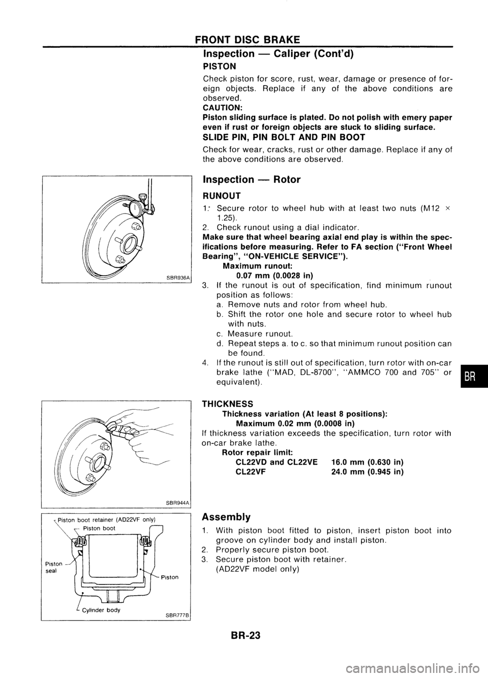
Pistonbootretainer (AD22VF only)
Piston boot
Piston seal
FRONT
DISCBRAKE
Inspection -Caliper (Cont'd)
PISTON
Check pistonforscore, rust,wear, damage orpresence offor-
eign objects. Replace ifany ofthe above conditions are
observed.
CAUTION:
Piston sliding surface isplated. Donot polish withemery paper
even ifrust orforeign objects arestuck tosliding surface.
SLIDE PIN,PINBOLT ANDPINBOOT
Check forwear, cracks, rustorother damage. Replaceifany of
the above conditions areobserved.
Inspection -Rotor
RUNOUT
1: Secure rotortowheel hubwith atleast twonuts (M12 x
1.25).
2. Check runout usingadial indicator.
Make surethatwheel bearing axialendplay iswithin thespec-
ifications beforemeasuring. RefertoFA section ("FrontWheel
Bearing", "ON-VEHICLE SERVICE").
Maximum runout:
SBR936A 0.07mm(0.0028 in)
3.
If
the runout isout ofspecification, findminimum runout
position asfollows:
a. Remove nutsandrotor fromwheel hub.
b. Shift therotor onehole andsecure rotortowheel hub
with nuts.
c. Measure runout.
d. Repeat stepsa.to c.so that minimum runoutposition can
be found.
4. Ifthe runout isstill outofspecification, turnrotor withon-car
brake lathe("MAD, DL-8700", "AMMCO700and 705" or•••
equivalent).
THICKNESS Thickness variation(Atleast 8positions):
Maximum 0.02mm(0.0008 in)
If thickness variationexceedsthespecification, turnrotor with
on-car brakelathe.
Rotor repair limit:
CL22VD andCL22VE 16.0mm(0.630 in)
CL22VF 24.0mm(0.945 in)
SBR944A Assembly
1. With piston bootfitted topiston, insertpiston bootinto
groove oncylinder bodyandinstall piston.
2. Properly securepistonboot.
3. Secure pistonbootwithretainer.
(AD22VF modelonly)
Piston
SBR777B BR-23
Page 303 of 1701
SBR847
SBR247B REAR
DISCBRAKE
Inspection -Rotor
RUBBING SURFACE
Check rotorforroughness, cracksorchips.
RUNOUT
1. Secure rotortowheel hubwith atleast twonuts (M12 x1.25).
2. Check runout usingadial indicator.
Make surethatwheel bearing axialendplay iswithin thespec-
ifications beforemeasuring. Referto"Rear Wheel Bearing" of
"ON-VEHICLE SERVICE"inRA section.
3. Change relativepositions ofrotor andwheel hubsothat
runout isminimized.
Maximum runout:
0.07 mm(0.0028 in)
THICKNESS Rotor repair limit:
Minimum thickness
CL7HB 6.0mm (0.236 in)
CL9HC 8.0mm (0.315 in)
Thickness variation(Atleast 8portions)
Maximum 0.02mm(0.0008 in)
Replace rotorifany ofthe above donot meet thespecifications .
Assembly
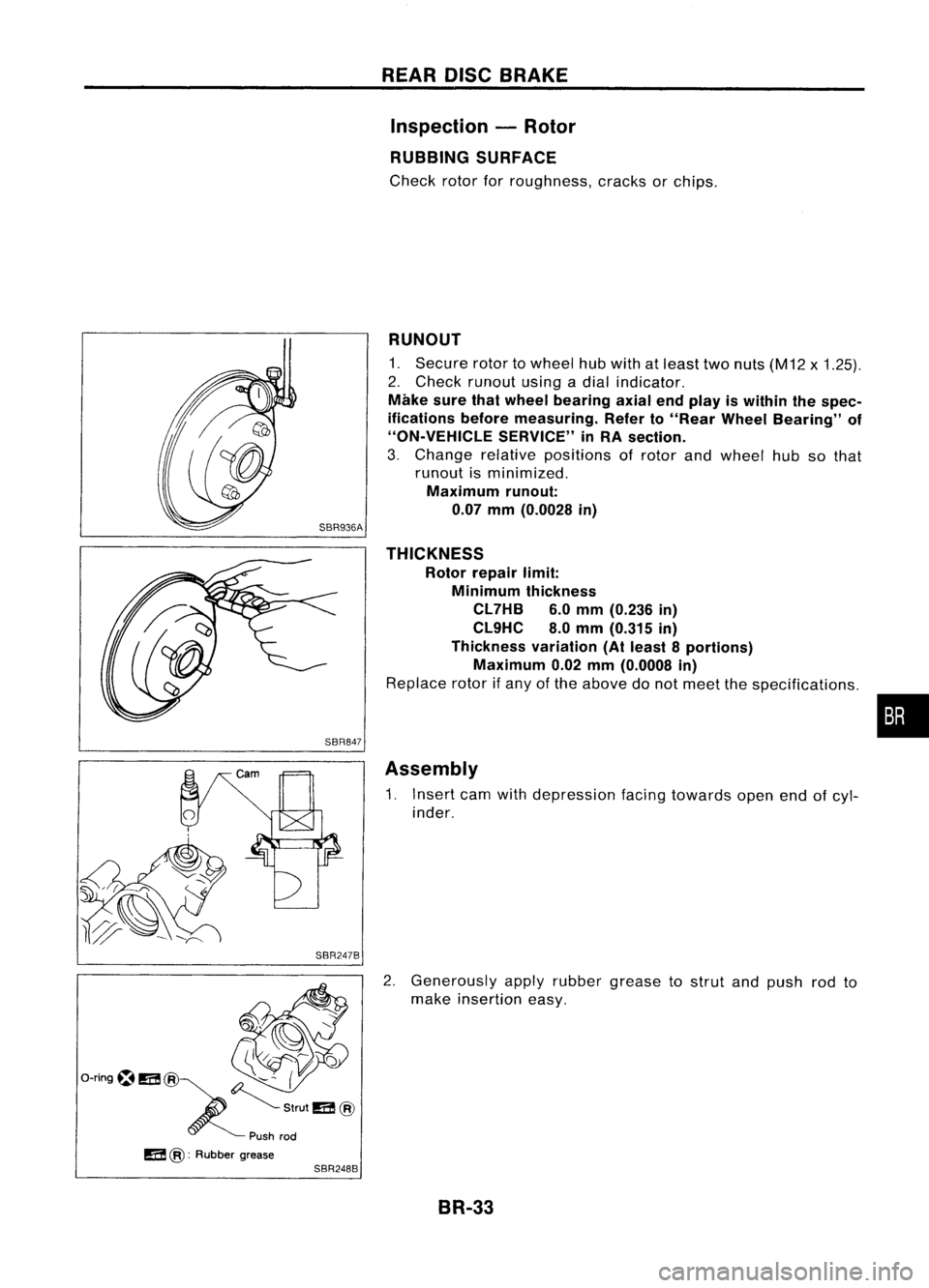
1. Insert camwithdepression facingtowards openendofcyl-
inder.
2. Generously applyrubber grease tostrut andpush rodto
make insertion easy.
BR-33
•
Page 623 of 1701
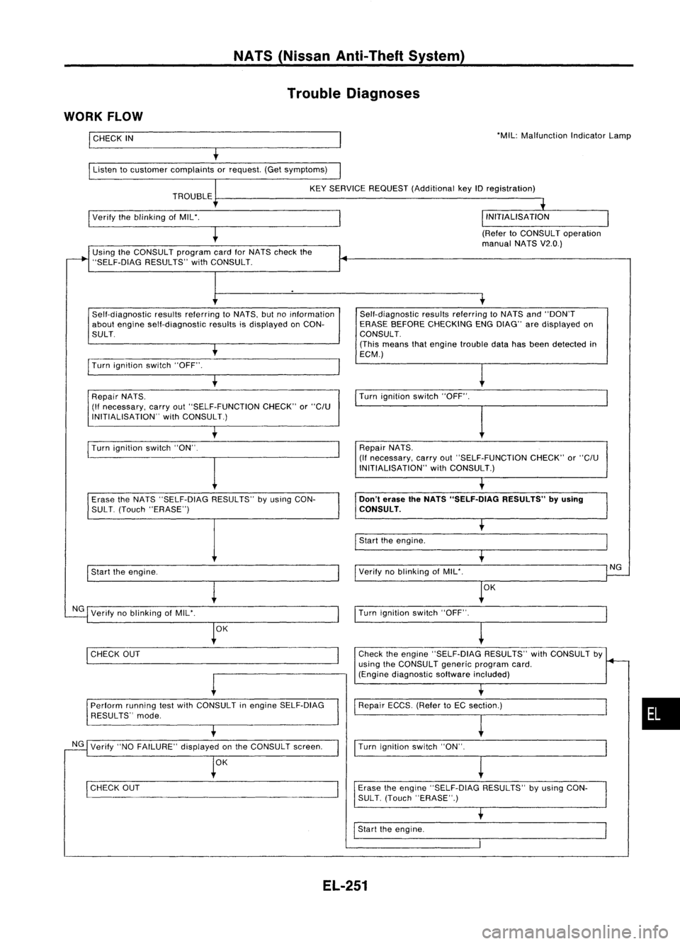
NATS(Nissan Anti-Theft System)
Trouble Diagnoses
WORK FLOW
I
CHECK
IN
Listen tocustomer complaints orrequest. (Getsymptoms) 'MIL:
Malfunction IndicatorLamp
KEY SERVICE REQUEST (Additional keyIDregistration)
TROUBLE
I
Verify theblinking ofMIL'.
(RefertoCONSULT operation
manual NATSV2.0.)
Using theCONSULT programcardforNATS check the
"SELF-DiAG RESULTS"withCONSULT.
Self-diagnostic resultsreferring toNATS, butnoinformation
about engine self-diagnostic resultsisdisplayed onCON-
SULT.
I
Turn ignition switch"OFF".
t
Repair NATS.
(If necessary, carryout"SELF-FUNCTION CHECK"or
"C/U
INITIALISATION" withCONSULT.) Self-diagnostic
resultsreferring toNATS and"DON'T
ERASE BEFORE CHECKING ENGDIAG" aredisplayed on
CONSULT.
(This means thatengine trouble datahasbeen detected in
ECM.)
Turn ignition switch"OFF".
I
Turn ignition switch"ON".
I
Repair
NATS.
(If necessary, carryout"SELF-FUNCTION CHECK"or
"C/U
INITIALISATION" withCONSULT.)
Erase theNATS "SELF-DIAG RESULTS"byusing CON-
SUL T.(Touch "ERASE")
I
Start theengine.
NG Verify noblinking ofMIL'.
OK
I
CHECK OUT
-
Perform runningtestwith CONSULT inengine SELF-DiAG
RESULTS" mode.
NG Verify "NOFAILURE" displayedonthe CONSULT screen.
OK
I
CHECK OUT
Don't
erase theNATS "SELF.DlAG RESULTS"byusing
CONSULT.
I
Start theengine.
Verify noblinking ofMIL'.
OK
I
Turn ignition switch"OFF".
~
Check theengine "SELF-DiAG RESULTS"withCONSULT by
using theCONSULT genericprogram card.
(Engine diagnostic softwareincluded)
Repair ECCS.(RefertoEC section.)
I
Turn ignition switch"ON".
Erase theengine "SELF-DIAG RESULTS"byusing CON-
SUL T.(Touch "ERASE".)
I
Start theengine.
NG
•
EL-251
Page 687 of 1701
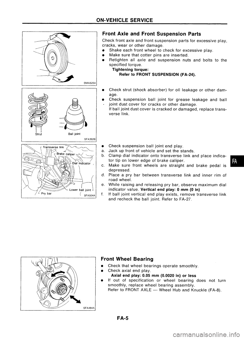
SMA525AON-VEHICLE
SERVICE
Front AxleandFront Suspension Parts
Check frontaxleandfront suspension partsforexcessive play,
cracks, wearorother damage.
• Shake eachfrontwheel tocheck forexcessive play.
• Make surethatcotter pinsareinserted.
• Retighten allaxle andsuspension nutsandbolts tothe
specified torque.
Tightening torque:
Refer toFRONT SUSPENSION (FA-24).
Strut
Ball
joint
SFA392B
•
Check strut(shock absorber) foroilleakage orother dam-
age.
• Check suspension balljoint forgrease leakage andball
joint dustcover forcracks orother damage.
If ball joint dustcover iscracked ordamaged, replacetrans-
verse link.
• Check suspension balljoint endplay.
a. Jack upfront ofvehicle andsetthe stands.
b. Clamp dialindicator ontotransverse linkand place indica- •
tor tiponlower edgeofbrake caliper. •
c. Make surefront wheels arestraight andbrake pedalis
depressed.
d. Place apry bar between transverse linkand inner rimof
road wheel.
e. While raising andreleasing prybar, observe maximum dial
indicator value.
Vertical endplay: 0mm (0in)
f. Ifball joint vertical endplay exists, remove transverse link
and recheck theball joint. Refer toFA-27.
SFA484A Front
Wheel Bearing
• Check thatwheel bearings operatesmoothly.
• Check axialendplay.
Axial endplay: 0.05mm(0.0020 in)orless
• If
out ofspecification orwheel bearing doesnotturn
smoothly, replacewheelbearing assembly.
Refer toFRONT AXLE-Wheel HubandKnuckle (FA-B).
FA-5
Page 720 of 1701
ENGINECONTROL SYSTEM
SECTION
EC
CONTENTS
•
PRECAUTIONS ANDPREPARATION
4
Special Service Tools 4
Supplemental RestraintSystem(SRS)"AIR
BAG" (DualAirBag System) 7
Supplemental RestraintSystem(SRS)"AIR
BAG" (Single AirBag System) 7
GA,SR
PRECAUTIONS ANDPREPARATION
8
Engine Fuel
&
Emission ControlSystem 8
Precautions forECCS Trouble Diagnosis of
Engine 9
Precautions 9
ENGINE ANDEMISSION CONTROLOVERALL
SYSTEM 11
Circuit Diagram -Except forAustralia 11
Circuit Diagram -For Australia 12
System Diagram -GA 14DE, GA16DE for
Europe andIsrael 13
System Diagram -GA15DE 14
System Diagram -GA 16DE except for
Europe, IsraelandAustralia 15
System Diagram -GA 16DE forAustralia 16
ECCS Component PartsLocation -GA 14DE,
GA 16DE forEurope andIsrael 17
ECCS Component PartsLocation -GA15DE 18
ECCS Component PartsLocation -GA 16DE
except forEurope, IsraelandAustralia 19
ECCS Component PartsLocation -GA 16DE
for Austral ia 20
ECCS Component PartsLocation 21
Vacuum HoseDrawing 22
c=
~
GA
ENGINE
ANDEMISSION BASICCONTROL
SYSTEM DESCRiPTION 23
System Chart.. 23
Multiport FuelInjection (MFI)System 24
Distributor Ignition(01)System 27
Air Conditioning CutControl 28
Fuel CutControl (atnoload &high engine
speed) 28
EVAPORATIVE EMISSIONSYSTEM
29
Inspection 29
POSITIVE CRANKCASE VENTILATION 31
Description 31
Inspection 32
BASIC SERVICE PROCEDURE 33
Fuel Pressure Release 33
Fuel Pressure Check 33
Fuel Pressure Regulator Check 33
Injector Removal andInstallation 34
Idle Speed/lgnition Timing/ldleMixtureRatio
Adjustment ,35
ON-BOARD DIAGNOSTIC SYSTEMDESCRIPTION .44
Malfunction IndicatorLamp(MIL) 44
CONSULT .48
TROUBLE DIAGNOSIS -General Description
58
Introduction 58
Work Flow 59
Description forWork Flow 60
Diagnostic Worksheet 61
Diagnostic TroubleCode(DTC) Chart 62
Fail-Safe Chart 64
Basic Inspection 65
Fast IdleCam (FIC) Inspection and
Adjustment -For Europe andIsrael 68
Fast IdleCam (FIC) Inspection and
Adjustment -Except forEurope andIsrael. 68
Symptom MatrixChart 71
Page 721 of 1701
CONTENTS(Cont'd.)
CONSULT Reference ValueinData Monitor
Mode 74
Major Sensor Reference GraphinData
Monitor Mode 76
ECM Terminals andReference Value 78
TROUBLE DIAGNOSIS FORPOWER SUPPLY 88
Main Power Supply andGround Circuit.. 88
TROUBLE DIAGNOSIS FORDTC11 94
Camshaft PositionSensor(CMPS) 94
TROUBLE DIAGNOSIS FORDTC
12 101
Mass AirFlow Sensor (MAFS) 101
TROUBLE DIAGNOSIS FORDTC
13 108
Engine Coolant Temperature Sensor(ECTS) 108
TROUBLE DIAGNOSIS FORDTC
21 113
Ignition Signal 113
TROUBLE DIAGNOSIS FORDTC
34 119
Knock Sensor (KS) 119
TROUBLE DIAGNOSIS FORDTC
41 124
Intake AirTemperature Sensor(IATS) 124
TROUBLE DIAGNOSIS FORNON-DETECTABLE
ITEMS , '"
.128
Throttle Position Sensor 128
Vehicle SpeedSensor (VSS) 133
Start Signal 138
Injector 141
Fuel Pump 145
Idle AirControl Valve(IACV) -Auxiliary Air
Control (AAC)Valve 150
Cooling FanControl 156
Power Steering OilPressure Switch 169
Park/Neutral PositionSwitch 173
EVAP Canister PurgeControl Solenoid Valve179
EGR Valve andEVAP Canister PurgeControl
Solenoid Valve 183
Heated Oxygen Sensor(H02S) 189
Oxygen Sensor(02S) 194
Valve Timing Control (VTC) 198
IACV-FICD SolenoidValve 204
Electrical LoadSignal 211
Torque Converter ClutchSolenoid Valve 219
MIL
&
Data LinkConnectors 223
SR
ENGINE ANDEMISSION CONTROL OVERALL
SYSTE M
226
Circuit Diagram 226
System Diagram 227
ECCS Component PartsLocation 228
Vacuum HoseDrawing 231
System Chart... 232
ENGINE
ANDEMISSION BASICCONTROL
SYSTEM DESCRiPTION
233
Multipart FuelInjection (MFI)System 233
Distributor Ignition
(01)
System 235
Air Conditioning CutControl 236
Fuel CutControl (atnoload
&
high engine
speed) 237
EVAPORATIVE EMISSIONSYSTEM
238
Description 238
Inspection 238
POSITIVE CRANKCASE VENTILATION
240
Description 240
Inspection 240
BASIC SERVICE
PROCEDURE 241
Fuel Pressure Release 241
Fuel Pressure Check 241
Fuel Pressure Regulator Check 242
Injector Removal andInstallation 242
Idle Speed/Ignition Timing/IdleMixtureRatio
Adjustment 243
ON-BOARD DIAGNOSTIC SYSTEMDESCRIPTION ..250
Malfunction IndicatorLamp(MIL) 250
CONSULT 254
TROUBLE DIAGNOSIS -General Description
264
Introduction 264
Work Flow 265
Description forWork Flow 266
Diagnostic Worksheet 267
Diagnostic TroubleCode(DTC) Chart 268
Fail-Safe Chart 270
Basic Inspection 271
Symptom MatrixChart. 274
CONSULT Reference ValueinData Monitor
Mode 277
Major Sensor Reference GraphinData
Monitor Mode 279
ECM"Terminals andReference Value 281
TROUBLE DIAGNOSIS FORPOWER SUPPLY
286
Main Power Supply andGround Circuit.. 286
TROUBLE DIAGNOSIS FORDTC
11 289
Camshaft PositionSensor(CMPS) 289
TROUBLE DIAGNOSIS FORDTC
12 293
Mass AirFlow Sensor (MAFS) 293
TROUBLE DIAGNOSIS FORDTC
13 297
Engine Coolant Temperature Sensor(ECTS) 297
TROUBLE DIAGNOSIS FORDTC
21 301
Ignition Signal 301
TROUBLE DIAGNOSIS FORDTC
34 306
Knock Sensor (KS) 306
Page 722 of 1701
CONTENTS(Cont'd.)
TROUBLE DIAGNOSIS FORDTC
43 309
Throttle Position Sensor 309
TROUBLE DIAGNOSIS FORNON-DETECTABLE
ITEMS
314
Vehicle SpeedSensor (VSS) 314
Start Signal 317
Exhaust GasRecirculation (EGR)Valveand
EVAP Canister PurgeControl 319
Injector 324
Fuel Pump 327
Idle AirControl Valve(IACV)-Air Regulator 332
Idle AirControl Valve(IACV) -Auxiliary Air
Control (AAC)Valve :335
Idle AirControl Valve(IACV)-FICD Solenoid
Valve '"339
Cooling FanControl 343
Power Steering OilPressure Switch 354
Park/Neutral PositionSwitch 357
Heated Oxygen Sensor(H02S) 362
Torque
Converter
ClutchSolenoid Valve 367
Malfunction IndicatorLamp(MIL)
&
Data Link
Connector (DLC)forCONSULT 370
CD
INJECTION SYSTEM
371
VE.TYPE INJECTION PUMP
372
Removal 372
Installation 373
Adjustment 374
INJECTION NOZZLE
376
Removal andInstallation 376
Disassembly 376
Inspection 377
Cleaning 377
Assembly 378
Test andAdjustment 379
FUEL
SYSTEM CHECK
381
Priming PumpCheck 381
Fuel CutSolenoid Valve 381
CRANKCASE VENTILATION SYSTEM
382
Ventilation Hose 382
ENGINE ANDEMISSION CONTROLOVERALL
SYSTEM
383
Component PartsLocation 383
System Diagram 384
Circuit Diagram ,385
System Chart. 386
TROUBLE DIAGNOSES
387
ECM Terminals andReference Values 387
Quick-glow System 390
Partial LoadAdvance (PLA)Control 399
Cooling FanControl 404
Air Conditioner CutControl 413
Fuel CutControl 416
GA
SERVICE DATAANDSPECIFICATIONS
(505).417
General Specifications 417
Inspection andAdjustment.. 417
SR
SERVICE DATAANDSPECIFICATIONS
(505).418
General Specifications 418
Inspection andAdjustment.. .418
CD
SERVICE DATAANDSPECIFICATIONS
(505).419
VE-type Injection Pump 419
Injection Nozzle 419
•
When youread wiring diagrams:
• Read GIsection, "HOWTOREAD WIRING DIAGRAMS" .
• See Elsection, "POWER SUPPLYROUTING" forpower distribution circuit.
When youperform troublediagnoses, readGIsection, "HOWTOFOllOW FLOWCHART INTROU-
BLE DIAGNOSES" and"HOW TOPERFORM EFFICIENT DIAGNOSIS FORANELECTRICAL INCIDENT".