Page 789 of 1701
TROUBLEDIAGNOSIS -General Description
[]A]
Fast IdleCam (FIC) Inspection andAdjustment
- Except forEurope andIsrael (Cont'd)
For example:
CaseI Case
II
Thermo-element
25(77) 40(104)
temperature .C
l"F)
Thermo-element
specified stroke(Ls)
14.0
(0.551) 15.35(0.6043)
mm (in)
Thermo-element
14.5(0.571) 14.60(0.5748)
stroke (L)mm(in)
Revolutions of
14.5.
14.0 14.60-15.35
Z =
0.80
=0.63
I
Z=
0.80
=
-0.94
I
adjusting screw(Z)
0.571-0.551 0.5748.0.6043
mm/in
0.0315
=
0.63
0.0315
=
-0.94
Direction ofrevolu-
Counterclockwise Clockwise
tion
EC-70
Page 1093 of 1701

Preparation ofcold start device
1. Turn coldstart device linkage clockwise.
2. Set asuitable block[Th")
VE-TYPE INJECTION PUMP
SEF779A
Adjustment
INJECTION TIMINGADJUSTMENT (Plunger
lift
adjustment)
Preparation ofcold start device
1. Turn coldstart device linkage clockwise.
2. Set asuitable block[Thickness: about15mm (0.59 in)]
between coldstart device plunger andlinkage rod.
3. Turn crankshaft 2turns clockwise toset the device tonor-
mal position.
Checking
1. Set NO.1 piston atTDC onitscompression stroke.
TDC: Without paintedmark
2. Remove injection tubesandairbleeder onthe back ofinjec-
tion pump.
3. Set dial gauge soitsindicator pointstosomewhere between
1.0 and 2.0mm (0.039 and0.079 in)onthe scale.
4. Turn crankshaft 1turn clockwise andcheck thatdialgauge
indicates thesame value again.
5. Turn crankshaft counterclockwise about20to25 degrees,
then setdial gauge indicator to0mm (0in).
6. Turn crankshaft clockwiseandsetthe pump timing markto
the mark onthe crankshaft pulley.
Pump timing mark:Yellow painted mark
Injection timing:8
0
BTDC
7. Read plunger lift.
Plunger lift:
0.79 -0.85 mm(0.0311 -0.0335 in)atpump timing
mark
• When repeating thechecking, startwithstep 5.
Adjusting
1. Ifplunger liftisnot within thespecified value,adjust by
turning injection pump.
• Ifindication issmaller thanthespecified value,turnpump
body away fromengine.
• Ifindication islarger thanthespecified value,turnpump
body towards engine.
2. Tighten injection pumpsecuring boltsandnuts.
Nut:
~: 13-18 N.m (1.3-1.8 kg-m, 9-13 ft-Ib)
Bolt:
~: 49-59 N.m (5.0-6.0 kg-m, 36-43 ft-Ib)
3. Remove dialgauge andinstall airbleeder withnewwasher.
4. Install injection tubes.
Flare nut:
~: 22-25 N.m (2.2-2.5 kg-m, 16-18 ft-Ib)
5. Bleed airfrom fuelsystem.
Refer to"Water Draining, FuelFilter Check andReplacement"
of "ENGINE MAINTENANCE" inMA section.
EC-374
Page 1202 of 1701
TIMINGCHAIN
Inspection
Check forcracks andexcessive wearatroller links.Replace if
necessary.
•
SEM1190
No. 1cylinder atTDC
Installation
1. Position crankshaft sothat No.1piston isat TOC andkey
way isat 12 o'clock.
a. Install crankshaft sprocket.
• Make suremating marksoncrankshaft sprocketfacefront
of engine.
b. Install oilpump drivespacer.
SEM377CC
--40
rollers
2.
Install chainguide.
3. Install crankshaft sprocketandlower timing chain.
• Settiming chainbyaligning itsmating markwiththeone on
crankshaft sprocket.
• Make suresprocket's matingmarkfaces engine front.
• The number oflinks between alignment marksare thesame
for the leftand ri.Qht sides. Eithersidecanbeused during
alignment withthesprocket.
SEM127F
/
Same number link
///
40 rollers-
• :Mating mark(different color)
EM-23
Page 1204 of 1701

Ol
\"\"
E
z
~ 29.4 (3,22)
E!\"
2
Ol
c
'c
QJ
.E
Cl
i=
SEM877A
SEM124D
S")
o
Cylinder
headboltwasher
0 __ 0
•
Cylinder headside
Tighten innumerical order.
~ 58.8 (6,43)
Ol
""
E
z
~ 29.4 (3,22)
E!"
2
Ol
c
'c
QJ
.E
Cl
i=
SEM877A
SEM124D
SEM614EA TIMING
CHAIN
[]K]
Installation (Cont'd)
15. Install cylinder headwithnewgasket.
• Besure toinstall washers betweenboltsandcylinder head.
• Donot rotate crankshaft andcamshaft separately, orvalves
will strike piston heads.
• Apply newengine oiltocylinder headboltthreads andseat
surfaces.
• Tightening procedure
@
Tighten boltsto29.4 N'm (3kg-m, 22ft-Ib).
@
Tighten boltsto58.8 N'm(6kg-m, 43ft-Ib).
@
Loosen boltscompletely.
@
Tighten boltsto29.4 N'm (3kg-m, 22ft-Ib).
@
Turn bolts 50to55 degrees clockwise orifangle wrench is
not available, tightenboltsto58.8:1: 4.9N'm (6:1:0.5kg-m,
43.4:1: 3.6ft-Ib).
CD
Tighten bolts
(@-@)
to6.3 to8.3 N'm (0.64 to0.85 kg-m,
55.6 to73.8 in-Ib).
Tightening torqueN'm(kg-m, ft-Ib)
@
@
@
@
@,CD
50 -55
degrees or
Bolts 29.4(3,22) 58.8 (6,43) 0(0,0) 58.8:1:4.9
((1) -
@»)
29.4
(3,22)
(6:1:0.5,
43.4:1: 3.6
ft-Ib)
6.3 -8.3
Bolts (0.64
-
(@ -@)
-
- -
-
0.85,55.6 -
73.8 in-Ib)
16. Install idlersprocket bolt.
•
Intake Exhaust
17.
Install camshaft.
• Make surecamshafts arealigned asshown infigure.
SEM547D EM-25
Page 1237 of 1701
Rearoilseal retainer
SEM736DCYLINDER
BLOCK
[ill
Assembly (Cont'd)
b. Install connecting rodcaps.
Tighten connecting rodcap nuts tothe specified torque.
tD.J:
Connecting rodcap nuts
(1) Tighten to13.72 to15.68 N'm(1.399 to1.599
kg-m, 10.120 to11.566 ft-Ib).
(2) Turn nutsto35° to40° degrees clockwise withan
angle wrench. Ifan angle wrench isnot avail-
able tighten nutsto23 to28 N'm (2.3to2.9 kg-m,
17 to21 ft-Ib).
6. Measure connecting rodside clearance.
Connecting rodside clearance:
Standard:
0.200 -0.470 mm(0.0079 -0.0185 in)
limit:
0.52 mm(0.0205 in)
If beyond thelimit, replace connecting rod
and/or crankshaft.
7. Install rearoilseal retainer.
a. Before installing rearoilseal retainer, removealltraces of
liquid gasket fromcylinder blockandretainer witha
scraper.
b. Apply acontinuous beadofliquid gasket torear oilseal
retainer.
• Apply around innersideofbolt holes.
EM-58
Page 1253 of 1701
@
~c
t':'
CO',
M''''',mwk
Mating markC
~!
56
coli'" ~
t..
coli."
CD
Mating mark
SEM500E TIMING
CHAIN
[]K]
Installation (Cont'd)
2. Position crankshaft sothat No.1 piston isset atTOG andkey
way isat 12 o'clock. Fittiming chainoncrankshaft sprocket,
aligning themating marks.
• Mating markcolorontiming chain.
eD
Gold
@,
CID:
Silver
3. Install timing chainandtiming chainguides.
4. Before installing frontcover, remove alltraces ofliquid
gasket frommating surface usingascraper.
• Also remove tracesofliquid gasket frommating surface of
cylinder block.
5. Apply acontinuous beadofliquid gasket tomating surface
of front cover.
• Use Genuine LiquidGasket orequivalent.
• Besure toinstall newfront oilseal inthe right direction.
Refer toEM-82.
EM-74
Page 1256 of 1701
MethodA
Method B 90+5degrees
-0
Engine Paint
mark
front
:0
118
~
(12,87)
Plasticzone
EO
78
0,
(8,58)
~
E
39
z
(4,29)
SEM074DATIMING
CHAIN
[]B]
Installation (Cont'd)
@
Method A:Turn allbolts 90to95 degrees clockwise with
Tool orsuitable anglewrench.
Method B:
If
angle wrench isnot available, dothe follow-
ing. Mark theside ofall bolts withpaint marks
facing thefront ofthe engine. Thenturnthem 90
to 95 degrees clockwise.
CD
Turn allbolts 90to95 degrees clockwise. •
@
Ensure thatpaint mark oneach boltfaces therear ofthe
engine. (Method Bonly)
Do not turn anybolt 180to190 degrees clockwise allatonce.
Tightening torqueN'm(kg-m, ft-Ib)
@
39(4.0, 29)
@
78(8.0, 58)
@
0(0,0)
@
34-44 (3.5 -4.5, 25-33)
@
90-95 degrees (90degree preferred)
CD
90
-95 degrees (90degree preferred)
14. Install cylinder headoutside bolts.
15. Install thefollowing waterhoses.
• Water hoseforcylinder block.
• Water hosesforheater.
16. Install knocksensor harness connector.
EM-77
Page 1257 of 1701
SEM354D
f'J
liquid gasket
Apply
liquidgasket
to the hatched area.
o ~
LHcamshaft endbracket
SEM075DA
RH camShaft./'::~nd bracket
brackey
0
Edb kt
~ "nrace
(1)
~~~;~ ~.o
o.
00'{'
NO.1 to4
0
brackets LHcamshaft
NO.1 to4brackets bracket
SEM098DA TIMING
CHAIN
Installation (Cont'd)
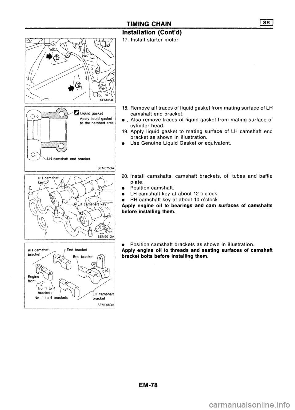
17. Install starter motor.
18. Remove alltraces ofliquid gasket frommating surface ofLH
camshaft endbracket.
•. Also remove tracesofliquid gasket frommating surface of
cylinder head.
19. Apply liquidgasket tomating surface ofLH camshaft end
bracket asshown inillustration.
• Use Genuine LiquidGasket orequivalent.
20. Install camshafts, camshaftbrackets,oiltubes andbaffle
plate.
• Position camshaft.
• LHcamshaft keyatabout 12o'clock
• RHcamshaft keyatabout 10o'clock
Apply engine oiltobearings andcam surfaces ofcamshafts
before installing them.
• Position camshaft bracketsasshown inillustration.
Apply engine oiltothreads andseating surfaces ofcamshaft
bracket boltsbefore installing them.
EM-78
![NISSAN ALMERA N15 1995 Service Manual TROUBLEDIAGNOSIS -General Description
[]A]
Fast IdleCam (FIC) Inspection andAdjustment
- Except forEurope andIsrael (Cont'd)
For example:
CaseI Case
II
Thermo-element
25(77) 40(104)
temperatu](/manual-img/5/57349/w960_57349-788.png "NISSAN ALMERA N15 1995 Service Manual TROUBLEDIAGNOSIS -General Description
[]A]
Fast IdleCam (FIC) Inspection andAdjustment
- Except forEurope andIsrael (Cont'd)
For example:
CaseI Case
II
Thermo-element
25(77) 40(104)
temperatu")


b. Install connecting rodcaps.
Tighten connecting rodcap nuts tothe specified torque.
tD.J:
Connecting rodcap nuts
(1) Tigh")
![NISSAN ALMERA N15 1995 Service Manual
@
~c
t':'
CO',
M''''',mwk
Mating markC
~!
56
coli'" ~
t..
coli."
CD
Mating mark
SEM500E TIMING
CHAIN
[]K]
Installation (Cont'd)
2. Positio](/manual-img/5/57349/w960_57349-1252.png "NISSAN ALMERA N15 1995 Service Manual
@
~c
t':'
CO',
M''''',mwk
Mating markC
~!
56
coli'\" ~
t..
coli.\"
CD
Mating mark
SEM500E TIMING
CHAIN
[]K]
Installation (Cont'd)
2. Positio")
![NISSAN ALMERA N15 1995 Service Manual MethodA
Method B 90+5degrees
-0
Engine Paint
mark
front
:0
118
~
(12,87)
Plasticzone
EO
78
0,
(8,58)
~
E
39
z
(4,29)
SEM074DATIMING
CHAIN
[]B]
Installation (Cont'd)
@
Method](/manual-img/5/57349/w960_57349-1255.png "NISSAN ALMERA N15 1995 Service Manual MethodA
Method B 90+5degrees
-0
Engine Paint
mark
front
:0
118
~
(12,87)
Plasticzone
EO
78
0,
(8,58)
~
E
39
z
(4,29)
SEM074DATIMING
CHAIN
[]B]
Installation (Cont'd)
@
Method")