Page 14 of 1701

DESCRIPTION
Shift Mechanism
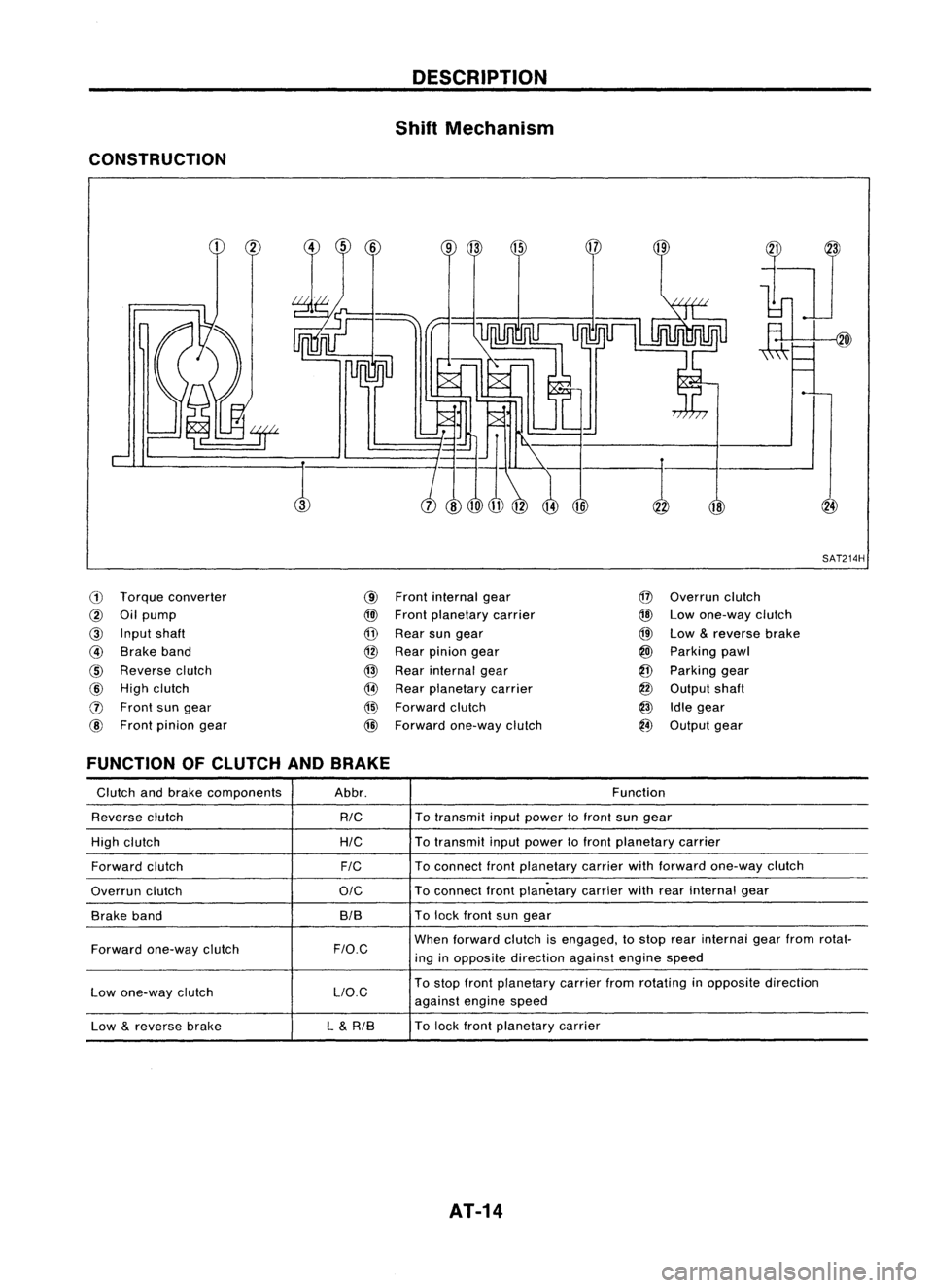
CONSTRUCTION
18
,:-1
SAT214H
ill
Torque converter
@
Oilpump
@
Input shaft
@
Brake band
@
Reverse clutch
@
High clutch
o
Front sungear
@
Front pinion gear
@
Front internal gear
@l
Front planetary carrier
@
Rear sungear
@
Rear pinion gear
@
Rear internal gear
@
Rear planetary carrier
@
Forward clutch
@
Forward one-way clutch
@
Overrun clutch
@
Lowone-way clutch
@
Low
&
reverse brake
@
Parking pawl
@
Parking gear
@
Output shaft
@
Idlegear
@
Output gear
FUNCTION OFCLUTCH ANDBRAKE
Glutch andbrake components Abbr. Function
Reverse clutch
RIG
To
transmit inputpower tofront sungear
High clutch
HIG
To
transmit inputpower tofront planetary carrier
Forward clutch
FIG
To
connect frontplanetary carrierwithforward one-way clutch
Overrun clutch
OIG
To
connect frontplanetary carrierwithrearinternal gear
Brake band BIBTo
lock front sungear
Forward one-way clutch
F/O.G
When
forward clutchisengaged, tostop rearinternai gearfrom rotat-
ing inopposite direction againstenginespeed
Low one-way clutch LlO.GTo
stop front planetary carrierfromrotating inopposite direction
against enginespeed
Low
&
reverse brake L
&
RIB To
lock front planetary carrier
AT-14
Page 15 of 1701

DESCRIPTION
Shift Mechanism (Cont'd)
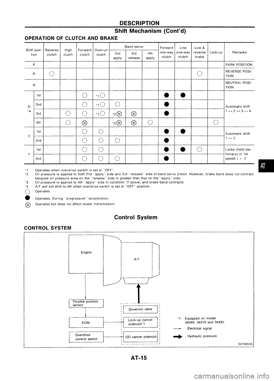
OPERATION OFCLUTCH ANDBRAKE
Bandservo
ForwardLow
Low
&
Shift posi- Reverse
HighForward
Overrun
Lock-upRemarks
tion clutch clutchclutchclutch 2nd
3rd4thone-way
one-way reverse
apply release
applyclutch
clutch brake
P PARK
POSITION
0 0REVERSE
POSI-
R TION
N NEUTRAL
POSI-
TION
1st 0'10
••
D 2nd
0'10
0
•
Automatic
shift
'4 00'10
'2@
@
•
1<-->2<-->3<-->4
3rd
4th 0@ '3@
@0
0
1st 00
••
Automatic
shift
2 1<-->2
2nd 00 0
•
1st 00
•
•
0
Locks
(heldsta-
1 tionary)
in1st
2nd 00 0
•
speed
1
<--
2
'1 Operates whenoverdrive switchissel to"OFF".
'2 Oilpressure isapplied toboth 2nd"apply" sideand3rd"release" sideofband servo piston. However, brakebanddoes notcontract
because oilpressure areaonthe "release" sideisgreater thanthatonthe "apply" side.
'3 Oilpressure isapplied to4th "apply" sideincondition '2above, andbrake bandcontracts.
'4 AIT
will notshift to4th when overdrive switchisset to"OFF" position.
o
Operates.
• Operates. During"progressive" acceleration.
@ Operates butdoes notaffect power transmission.
Control System
CONTROL SYSTEM
Engine
AIT
•
Lock-up cancel
solenoid'1
Overdrive
control switch
1:1
Governor valve
I
11
1
I
1
1
OD cancel solenoid :
; I
L
J
AT-15
'1:
Equipped onmodel
34X69, 34X70and34X80
: Electrical signal
.... :Hydraulic pressure
SAT985HA
Page 17 of 1701

Fluidleakage TROUBLE
DIAGNOSES
Preliminary Check(PriortoRoad Testing)
AIT FLUID CHECK
Fluid leakage check
1. Clean areasuspected ofleaking, -for example, mating
surface ofconverter housingandtransmission case.
2. Start engine, applyfootbrake, placeselector leverin"0"
position andwait afew minutes.
3. Stop engine.
4. Check forfresh leakage.
SAT288G
Fluidcondition check
Fluid levelcheck -Refer toMA section (CHASSIS AND
BODY MAINTENANCE).
Fluid
color
Oark orblack withburned odor
Milky pink
Varnished fluid,lighttodark brown
and tacky Suspected
problem
Wear offrictional material
Water contamination
- Road water entering through
filler tubeorbreather
Oxidation
- Over orunder filling
- Overheating
•
Road Testing
Perform roadtests using "Symptom" chart.Refertopage
AT-20.
"P"
POSITION
1. Place selector leverin"P" position andstart engine. Stop
engine andrepeat theprocedure inall positions, including
neutral position.
2. Stop vehicle onaslight upgrade andplace selector leverin
"P" position. Releaseparkingbraketomake surevehicle
remains locked.
"R"
POSITION
1. Manually moveselector leverfrom"P"to"R", andnote
shift quality.
2. Drive vehicle inreverse longenough todetect slippage or
other abnormalities.
"N"
POSITION
1. Manually moveselector leverfrom"R"and"0"to"N" and
note shift quality.
2. Release parkingbrakewithselector leverin"N" position.
Lightly depress accelerator pedaltomake surevehicle
does notmove. (When vehicle isnew orsoon afterclutches
have been replaced, vehiclemaymove slightly. Thisisnot
a problem.)
AT-17
Page 18 of 1701

SAT497GTROUBLE
DIAGNOSES
Road Testing (Cont'd)
"0"
POSITION
1. Manually moveselector leverfrom"N"to"D" position, and
note shiftquality.
2. Using theshift schedule asareference, drivevehicle in"D"
position. Record,onsymptom chart,respective vehicle
speeds atwhich up-shifting anddown-shifting occur.These
speeds aretobe read atthree different throttlepositions
(light, halfandfull), respectively. Alsodetermine thetiming
at which shocks areencountered duringshifting andwhich
clutches areengaged.
SAT612GA
3.Determine whetherlock-upproperly occurswhiledriving
vehicle inproper gearposition andatproper vehicle speed.
4. Check todetermine ifshifting tooverdrive gearcannot be
made whileODcontrol switchis"OFF".
5. Drive vehicle in"D
3"
position athalf tolight throttle posi-
tion. Keep driving at60 to70 km/h (34to43 MPH). FUlly
depress accelerator pedaltomake suretransaxle down-
shifts from3rdto2nd gear.
6. Drive vehicle in"D
2"
position athalf tolight throttle posi-
tion. Keep driving at25 to35 km/h (16to22 MPH). Fully
depress accelerator pedaltomake suretransaxle down-
shifts from2ndto1st gear.
"2"
POSITION
1. Shift to"2" position andmake surevehicle startsin1st
gear.
2. Increase vehiclespeedtomake suretransaxle upshiftsfrom
1st to2nd gear.
3. Further increase vehiclespeed.Makesuretransaxle does
not upshift to3rd gear.
4. Drive vehicle in"2
2"
position athalf tolight throttle position.
Keep driving at25 to35 km/h (16to22 MPH). Fullydepress
accelerator pedaltomake suretransaxle downshifts from
2nd to1st gear.
5. Allow vehicle torun idle while in"2" position tomake sure
that transaxle downshifts to1st gear.
6. Move selector leverto"D" position andallow vehicle to
operate at30 to40 km/h (19to25 MPH). Then,shiftto"2"
position tomake suretransaxle downshifts to2nd gear.
"1"
POSITION
1. Place selector leverin"1" position andaccelerate vehicle.
Make suretransaxle doesnotshift from 1stto2nd gear
although vehiclespeedincreases.
2. Drive vehicle in"1" position. Releaseaccelerator pedalto
make surethatengine compression actsasabrake.
3. Place selector leverin"D" or"2" position andallow vehi-
cle torun at15 to25 km/h (9to 16 MPH). Thenmove selec-
tor lever to"1" position tomake suretransaxle downshifts
to 1st gear.
AT-18
Page 25 of 1701
JUDGEMENT OFSTALL TEST
Selector leverposition
TROUBLE
DIAGNOSES
Stall Tasting (Cont'd)
Judgement
D
2
R
Damaged components
Forward one-way
cluth
Hydraulic circuitfor
line pressure control
(Line pressure islow.)
D
2
R
Selector leverposition H
H
H
o
H
H
H
H
o
o
o
H
o
o
o
o
Judgement
AT-25
L
L
L
L
o
:
Stall
revolution
isnormal.
H :Stall revolution ishigher
than specified.
L :Stall revolution islower
than specified.
Engine
Torque converter
one-way clutch
Reverse clutch
Low one-way clutch
Clutches andbrakes except
high clutch, brakebandand
overrun clutchareOK.
(Condition ofhigh clutch,
brake bandandoverrun
clutch cannot beconfirmed by
stall test.)
SAT871H
•
Page 28 of 1701
TROUBLEDIAGNOSES
Wiring Diagram -AT -
AT-A/T-01
page
Israel
Y ~Next page
A!T CONTROL
VAL VE
(E223) :
@
TORQUE
CONVERTER
CLUTCH
SOLENOID
VALVE
LHD
models
RHO models
For Europe and
Except@
GA engine
SR engine
(b):
:
@:
@:
@:
@:
Refer
toEL-POWER.
FUSE
BLOCK (J!B)
([@
(El06)
I
y ~.~ y
l---t~'~
Y ~(E202)
III
C~INATION
METER
(00OFF
INDICATOR) Y
~ t~)
11
2•6
1
@
300 CANCEL ~~
SOLENOID OR!BP!B
OR!B VALVE
I .-
I!::iJl
(E224) :
@
4~~
O~
OR!B
~1-
DRIB
I
OR!B
T
A
I
(BID
(Elan •
~o~
SR
.- .-1
P!B@l) P!B~
O~
OR!B~ DRIB
-ea-O~
OR!B~ OR!B
~O
/I;
II
E20l
II
i
II
E203
ORI!B
CBID
(El0n
L
@
(E20n
I
P!B~ P!B~
rm
SR
OR!B
-cz::n.
OR!B~
<0> ~
OVERDRIVE (E?6)
(E203)
0--1
CONTROL
L
OFF SWITCH
~ PIB-@>Next
ON
~
B
L
JOINT
CONNECTOR-1
~
B
~==~
B
r---------------------------------,
~(E224)
~GY
L ~
Refer
tolast page
(Foldout page).
CHID
(EtOn
,
([@
(El06)
,
~~
~W
~@D
~ B
~
(E202),~ ~
@J)
rn:rn:rz::rnJ
BGY
W@
B
ITIII:illIillIi ~
~ BR
HAT001
AT-28
Page 30 of 1701
TROUBLEDIAGNOSES
Electrical Components Inspection
OVERDRIVE CONTROLSWITCH
• Check continuity betweentwoterminals.
SAT0761
00
switch position
ON
OFF
Continuity
No
Yes
SAT0771
Model 34X68
SAT0781
Model 34X69, 34X70,34X80, 34X81
~i5
Gltm
~
SAT948HAINHIBITOR
SWITCH
• Check continuity in"N", "P"and "R" positions.
• With manual shaftheldin"N" position, turnmanual shaftan
equal amount inboth directions tosee ifcurrent flowposi-
tions arenearly thesame. (When manual leverisineach
position, continuity normallyexistswithin 1Sineither
direction.) Ifcurrent flowsoutside normalposition, orifnor-
mal flow position isout ofspecifications, properlyadjust
inhibitor switch.
Position TerminalNo. Continuity
Park/neutral position
@-@
No
Reverse position
@-@
Yes
00 CANCEL SOLENOID VALVEANDTORQUE
CONVERTER CLUTCHSOLENOID VALVE
• Check resistance betweenterminals.
Solenoids TerminalNo. Resistance
00 cancel solenoid
@-@
valve
Approximately250
Torque converter
CIJ-@
clutch solenoid valve
AT-30
Page 47 of 1701

MAJOROVERHAUL
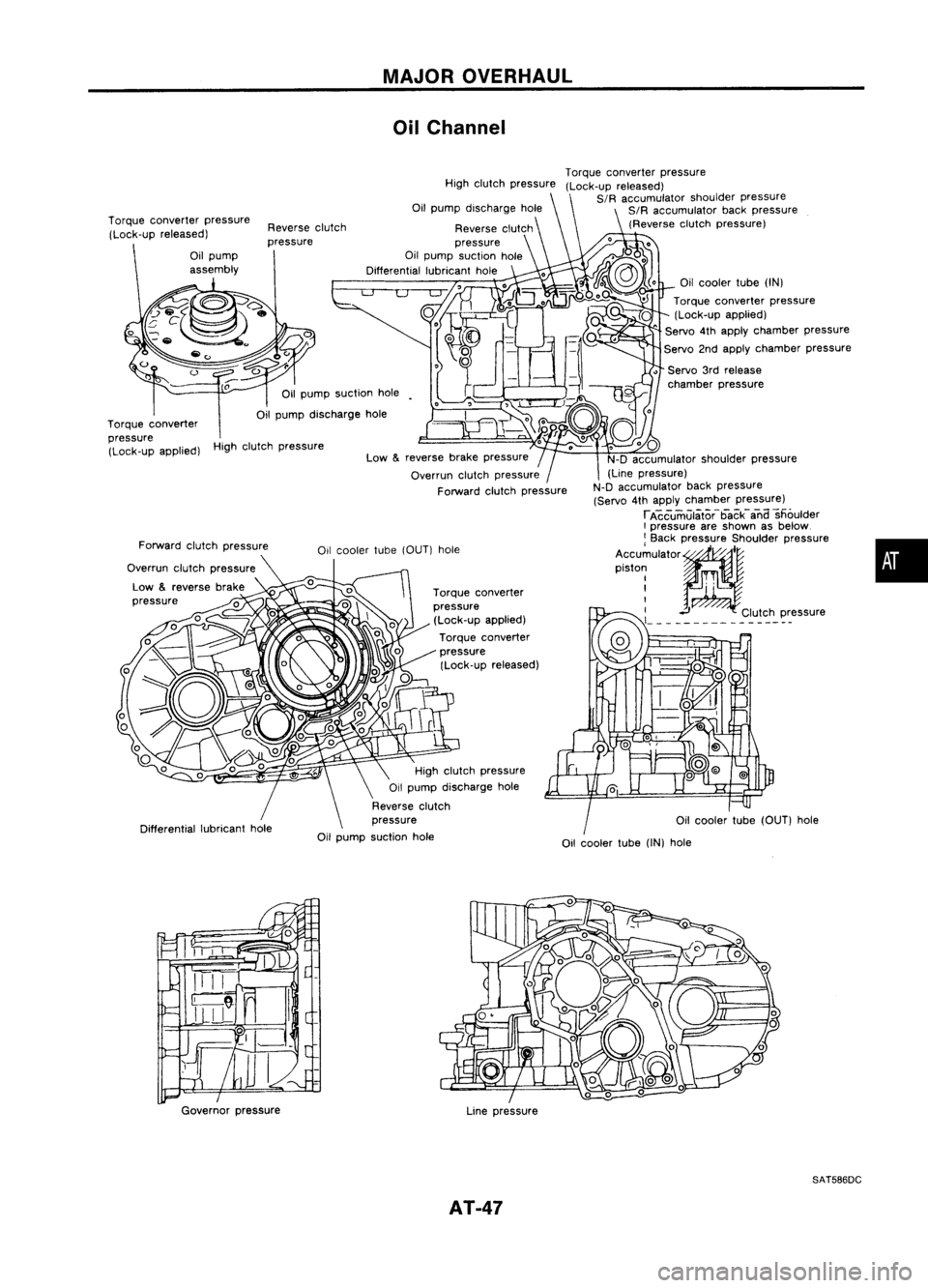
Oil Channel
High clutch pressure
Oilcooler tube(OUT) hole
•
Oil
cooler tube
(IN)
Torque converter pressure
(Lock-up applied)
" Servo
4th
apply chamber pressure
Servo 2ndapply chamber pressure
• Servo 3rdrelease
chamber pressure
Torque
converter pressure
(Lock-up released)
SIR accumulator shoulderpressure
SIR accumulator backpressure
(Reverse clutchpressure)
Oil cooler tube
(IN)
hole
Torque
converter
pressure (Lock-up applied)
Torque converter
pressure (Lock-up released)
reverse
brakepressure
Overrun clutchpressure
Forward clutchpressure
High
clutch pressure
Reverse clutch
pressure
Oil pump suction hole
Differential lubricanthole
High clutch pressure
Oil pump discharge hole
Reverse clutch
pressure
Oil pump suction hole
Reverse
clutch
pressure
Low
&
Oil
pump suction hole
Oil pump discharge hole
Forward clutchpressure
Overrun clutchpressure
Low
&
reverse brake
pressure
Torque
converter pressure
(Lock-up released)
Torque converter
pressure (Lock-up applied)
Governor pressure
Linepressure
SAT586DC
AT-47