1995 NISSAN ALMERA N15 Manual transaxle
[x] Cancel search: Manual transaxlePage 1 of 1701

AUTOMATICTRANSAXLE
SECTION
AT
CONTENTS
PREPARATION ANDPRECAUTIONS
3
Special Service Tools 3
Commercial ServiceTools 6
Service Notice 7
Supplemental RestraintSystem(SRS)"AIR
BAG" (DualAirBag System) 7
Supplemental RestraintSystem(SRS)"AIR
BAG" (Single AirBag System) 7
DESCRIPTION
8
Cross-sectional View 8
Hydraulic ControlCircuit 10
Shift Mechanism 14
Control System 15
TROUBLE DIAGNOSES 17
Preliminary Check(PriortoRoad Testing) 17
Road Testing 17
Stall Tasting 24
Pressure Testing 26
Wiring Diagram -AT - 28
Electrical Components Inspection 30
ON-VEHICLE SERVICE 31
Control ValveAssembly andAccumulator 31
Throttle WireAdjustment.. 33
Control CableInstallation andAdjustment 35
Governor Valve 36
Inhibitor SwitchAdjustment 37
Differential SideOilSeal Replacement.. 37
REMOVAL ANDINSTALLATION
39
Removal 39
Installation .40MAJOR
OVERHAUL.. 42
All Models 42
Except Model34X81 .44
Model 34X81 45•
Shift Control Components 46
i
Oil Channel 47
Locations ofAdjusting Shims,Needle
Bearings, ThrustWashers andSnap Rings -
Except Model34X81 .48
Locations ofAdjusting Shims,Needle
Bearings, ThrustWashers andSnap Rings -
Model 34X81 .49
DiSASSEMBLy 50
REPAIR FORCOMPONENT PARTS 66
Manual ShaftandThrottle Lever 66
Oil Pump 70
Control ValveAssembly 74
Control ValveUpper Body 86
Control ValveLower Body 90
Reverse Clutch 93
High Clutch 97
Forward ClutchandOverrun Clutch 102
Low &Reverse Brake 108
Rear Internal Gear,Forward ClutchHuband
Overrun ClutchHub 112
Output Shaft,Output Gear,IdlerGear,
Reduction PinionGearandBearing Retainer
- Except Model34X81 116
Output Shaft,IdlerGear, Reduction Pinion
Gear andBearing Retainer -Model 34X81 121
Band Servo Piston Assembly 126
Final Drive -Except Model34X81 131
Final Drive -Model 34X81 135
Page 7 of 1701

PREPARATIONANDPRECAUTIONS
Service Notice
Supplemental RestraintSystem(SRS)"AIR
BAG" (DualAirBag System)
The Supplemental RestraintSystem"AirBag" usedalong withaseat belt, helps toreduce therisk or
severity ofinjury tothe driver andfront passenger inafrontal collision. TheSupplemental Restraint
System consists ofair bag modules (locatedinthe center ofthe steering wheelandonthe instrument
panel onthe passenger side),adiagnosis sensorunit,warning lamp,wiring harness andspiral cable.
Information necessarytoservice thesystem safelyisincluded inthe
RSsection
ofthis Service Manual.
WARNING:
• Toavoid rendering theSRS inoperative, whichcouldincrease therisk ofpersonal injuryordeath
in the event ofacollision whichwould resultinair bag inflation, allmaintenance mustbeperformed
by an authorized NISSANdealer.
• Improper maintenance, includingincorrectremovalandinstallation ofthe SRS, canlead topersonal
injury caused byunintentional activationofthe system.
Ii
Donot use electrical testequipment onany circuit related tothe SRS unless instructed tointhis
Service Manual. SRSwiring harnesses arecovered withyellow insulation eitherjustbefore the
harness connectors orfor the complete harness,foreasy identification.
•
Before proceeding withdisassembly, thor-
oughly cleantheoutside ofthe transaxle. Itis
important toprevent theinternal partsfrom
becoming contaminated bydirt orother for-
eign matter.
• Disassembly shouldbedone inaclean work
area.
• Use lint-free clothortowels forwiping parts
clean. Common shopragscanleave fibers
that could interfere withtheoperation ofthe
transaxle.
• Place disassembled partsinorder, onaparts
rack, foreasier andproper assembly.
• Allparts should becarefully cleaned-witha
general purpose, non-flammable solvent
before inspection orreassembly.
• Gaskets, sealsandO-rings shouldbe
replaced anytime thetransaxle isdisassem-
bled.
• Itis very important toperform functional tests
whenever theyareindicated. •
The valve bodycontains precision partsand
requires extremecarewhen partsare
removed andserviced. Placedisassembled
valve bodyparts inorder, onaparts rack,for
easier andproper assembly. Carewillalso
prevent springs andsmall partsfrombecom-
ing scattered orlost.
• Properly installedvales,sleeves, plugs,etc.
will slide along theirbores inthe valve body
under theirownweight.
• Before assembly, applyacoat ofrecom-
mended ATFtoall parts. Apply petroleum
jelly toprotect O-ringandseals, orhold bear-
ings andwashers inplace during assembly.
Do not use grease.
• Extremely careshould betaken toavoid dam-
age toO-rings, sealsandgaskets when
assembling.
• After overhaul, refillthetransaxle withnew
ATF.
•
Supplemental RestraintSystem(SRS)"AIR
BAG" (Single AirBag System)
The Supplemental RestraintSystem"AirBag" andused along withaseat belt,helps toreduce therisk
or severity ofinjury tothe driver inafrontal collision. TheSupplemental RestraintSystemconsists of
an air bag module (located inthe center ofthe steering wheel),adiagnosis sensorunit,warning lamp,
wiring harness andspiral cable. Information necessarytoservice thesystem safelyisincluded inthe
RS section
ofthis Service Manual.
WARNING:
• Toavoid rendering theSRS inoperative, whichcouldincrease therisk ofpersonal injuryordeath
in the event ofacollision whichwould resultinair bag inflation, allmaintenance mustbeperformed
by an authorized NISSANdealer.
• Improper maintenance, includingincorrectremovalandinstallation ofthe SRS, canlead topersonal
injury caused byunintentional activationofthe system.
• Donot use electrical testequipment onany circuit related tothe SRS unless instructed tointhis
Service Manual.
AT-7
Page 18 of 1701

SAT497GTROUBLE
DIAGNOSES
Road Testing (Cont'd)
"0"
POSITION
1. Manually moveselector leverfrom"N"to"D" position, and
note shiftquality.
2. Using theshift schedule asareference, drivevehicle in"D"
position. Record,onsymptom chart,respective vehicle
speeds atwhich up-shifting anddown-shifting occur.These
speeds aretobe read atthree different throttlepositions
(light, halfandfull), respectively. Alsodetermine thetiming
at which shocks areencountered duringshifting andwhich
clutches areengaged.
SAT612GA
3.Determine whetherlock-upproperly occurswhiledriving
vehicle inproper gearposition andatproper vehicle speed.
4. Check todetermine ifshifting tooverdrive gearcannot be
made whileODcontrol switchis"OFF".
5. Drive vehicle in"D
3"
position athalf tolight throttle posi-
tion. Keep driving at60 to70 km/h (34to43 MPH). FUlly
depress accelerator pedaltomake suretransaxle down-
shifts from3rdto2nd gear.
6. Drive vehicle in"D
2"
position athalf tolight throttle posi-
tion. Keep driving at25 to35 km/h (16to22 MPH). Fully
depress accelerator pedaltomake suretransaxle down-
shifts from2ndto1st gear.
"2"
POSITION
1. Shift to"2" position andmake surevehicle startsin1st
gear.
2. Increase vehiclespeedtomake suretransaxle upshiftsfrom
1st to2nd gear.
3. Further increase vehiclespeed.Makesuretransaxle does
not upshift to3rd gear.
4. Drive vehicle in"2
2"
position athalf tolight throttle position.
Keep driving at25 to35 km/h (16to22 MPH). Fullydepress
accelerator pedaltomake suretransaxle downshifts from
2nd to1st gear.
5. Allow vehicle torun idle while in"2" position tomake sure
that transaxle downshifts to1st gear.
6. Move selector leverto"D" position andallow vehicle to
operate at30 to40 km/h (19to25 MPH). Then,shiftto"2"
position tomake suretransaxle downshifts to2nd gear.
"1"
POSITION
1. Place selector leverin"1" position andaccelerate vehicle.
Make suretransaxle doesnotshift from 1stto2nd gear
although vehiclespeedincreases.
2. Drive vehicle in"1" position. Releaseaccelerator pedalto
make surethatengine compression actsasabrake.
3. Place selector leverin"D" or"2" position andallow vehi-
cle torun at15 to25 km/h (9to 16 MPH). Thenmove selec-
tor lever to"1" position tomake suretransaxle downshifts
to 1st gear.
AT-18
Page 34 of 1701
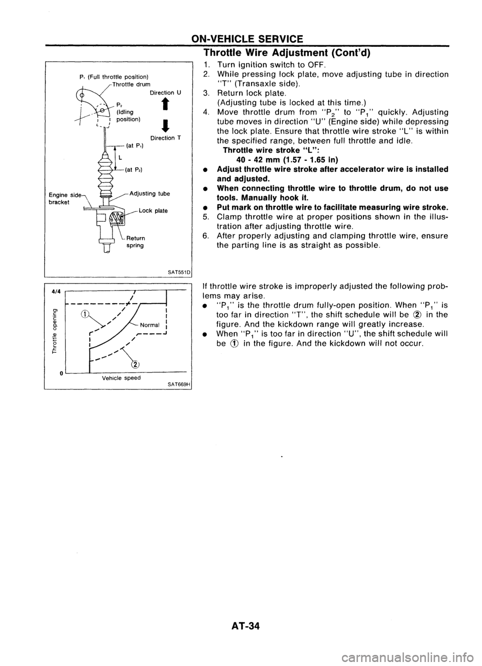
(atP,)
p,
(Full throttle position)
~ThrOttle drum
Direction U
, ,-- p,
t
I ~.
(Idling
--r ~_ .)
position)
I
Direction T
Engine side"
bracket (at
P,)
~ Adjusting tube
Lock plate ON-VEHICLE
SERVICE
Throttle WireAdjustment (Cont'd)
1. Turn ignition switchtoOFF.
2. While pressing lockplate, moveadjusting tubeindirection
"T" (Transaxle side).
3. Return lockplate.
(Adjusting tubeislocked atthis time.)
4. Move throttle drumfrom
"P2"
to
"P
1"
quickly. Adjusting
tube moves indirection "U"(Engine side)while depressing
the lock plate. Ensure thatthrottle wirestroke "L"iswithin
the specified range,between fullthrottle andidle.
Throttle wirestroke "L":
40 -42
mm
(1.57 -1.65
in)
• Adjust throttle wirestroke afteraccelerator wireisinstalled
and adjusted.
• When connecting throttlewiretothrottle drum,donot use
tools. Manually hookit.
• Put mark onthrottle wiretofacilitate measuring wirestroke.
5. Clamp throttle wireatproper positions showninthe illus-
tration afteradjusting throttlewire.
6. After properly adjusting andclamping throttlewire,ensure
the parting lineisas straight aspossible.
SAT551D
4/4
Vehiclespeed
If
throttle wirestroke isimproperly adjustedthefollowing prob-
lems mayarise.
• "P
1"
isthe throttle drumfully-open position.When"P
1"
is
too farindirection
"T",
theshift schedule willbe
@
inthe
figure. Andthekickdown rangewillgreatly increase.
• When
"P1"
istoo farindirection "U",theshift schedule will
be
CD
inthe figure. Andthekickdown willnotoccur.
SAT669H
I
I
Normal :
,- .J
,/
/
,,~/~
/
---------1--
,/
'//
r-/
I
I
o
0>
c:
C
Q)
0-
o
~
2
£
I-
AT-34
Page 36 of 1701
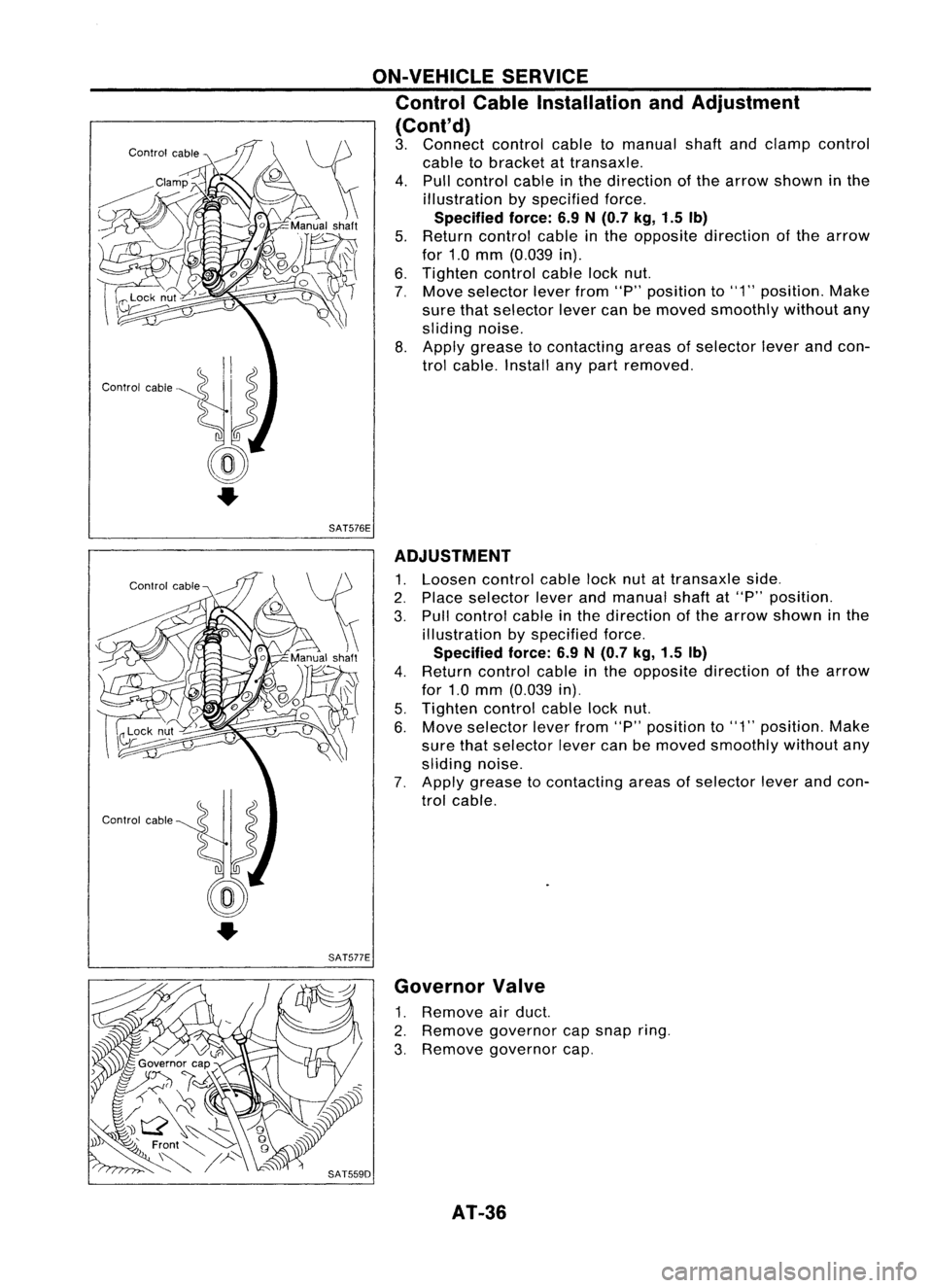
ON-VEHICLESERVICE
Control CableInstallation andAdjustment
(Cont'd)
3. Connect controlcabletomanual shaftandclamp control
cable tobracket attransaxle.
4. Pull control cableinthe direction ofthe arrow shown inthe
illustration byspecified force.
Specified force:6.9N(0.7 kg,1.5Ib)
5. Return control cableinthe opposite direction ofthe arrow
for 1.0mm (0.039 in).
6. Tighten controlcablelocknut.
7, Move selector leverfrom"P"position to"1" position. Make
sure thatselector levercanbemoved smoothly withoutany
sliding noise.
8. Apply grease tocontacting areasofselector leverandcon-
trol cable. Installanypart removed.
SAT576E
SAT577E ADJUSTMENT
1. Loosen controlcablelocknutattransaxle side.
2. Place selector leverandmanual shaftat"P" position.
3. Pull control cableinthe direction ofthe arrow shown inthe
illustration byspecified force.
Specified force:6.9N
(0.7
kg,1.5 Ib)
4. Return control cableinthe opposite direction ofthe arrow
for 1.0mm (0.039 in).
5. Tighten controlcablelocknut.
6. Move selector leverfrom"P"position to"1" position. Make
sure thatselector levercanbemoved smoothly withoutany
sliding noise.
7. Apply grease tocontacting areasofselector leverandcon-
trol cable.
Governor Valve
1. Remove airduct.
2. Remove governor capsnap ring.
3, Remove governor cap,
AT-36
Page 37 of 1701
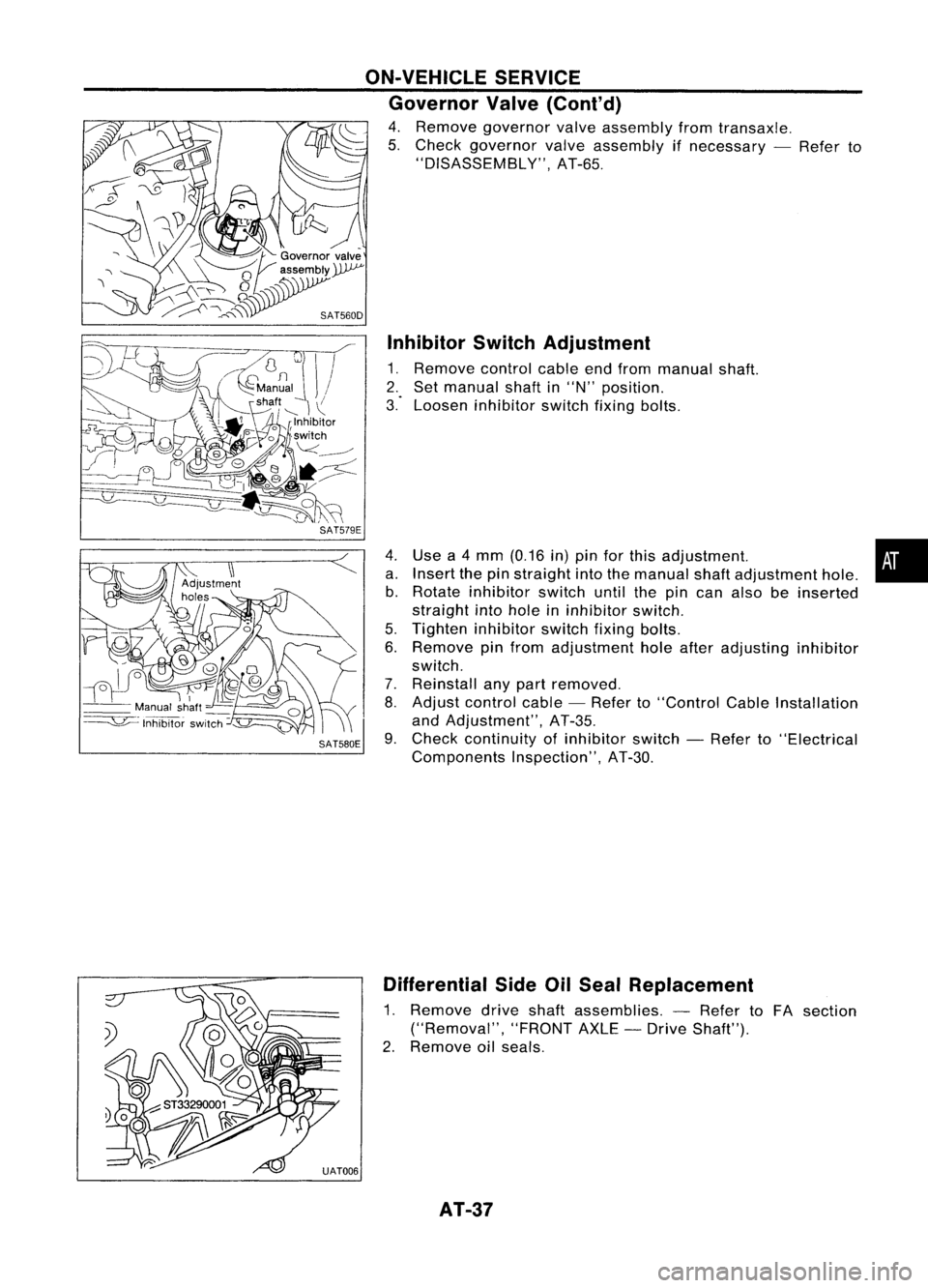
InhibitorSwitchAdjustment
1. Remove controlcableendfrom manual shaft.
2. Set manual shaftin"N" position.
3." Loosen inhibitor switchfixingbolts.
Use a4 mm (0.16 in)pin forthis adjustment. •
Insert thepinstraight intothemanual shaftadjustment hole.
Rotate inhibitor switchuntilthepincan also beinserted
straight intohole ininhibitor switch.
Tighten inhibitor switchfixingbolts.
Remove pinfrom adjustment holeafter adjusting inhibitor
switch.
Reinstall anypart removed.
Adjust control cable-Refer to"Control CableInstallation
and Adjustment", AT-35.
Check continuity ofinhibitor switch-Refer to"Electrical
Components Inspection",AT-30.
ON-VEHICLE
SERVICE
Governor Valve(Cont'd)
4. Remove governor valveassembly fromtransaxle.
5. Check governor valveassembly ifnecessary -Refer to
"DISASSEMBLY", AT-65.
4. a.b.
5.
6.
7.
8.
SAT580E 9.
Differential SideOilSeal Replacement
1. Remove driveshaftassemblies. -Refer toFA section
("Removal", "FRONTAXLE-Drive Shaft").
2. Remove oilseals.
AT-37
Page 1361 of 1701
HOWTOUSE THIS MANUAL
•
•
•
•
•
•
ALPHABETICAL
INDEXisprovided atthe end ofthis manual sothat youcan rapidly findtheitem •
and page youaresearching for.
A QUICK REFERENCE INDEX,ablack tab(e.g.
I=J;J)
is provided onthe first page. Youcanquickly
find thefirst page ofeach section bymating itto the section's blacktab.
THE CONTENTS arelisted onthe first page ofeach section .
THE TITLE isindicated onthe upper portion ofeach pageandshows thepart orsystem .
THE PAGE NUMBER ofeach section consists oftwo letters whichdesignate theparticular section
and anumber (e.g."BR-5").
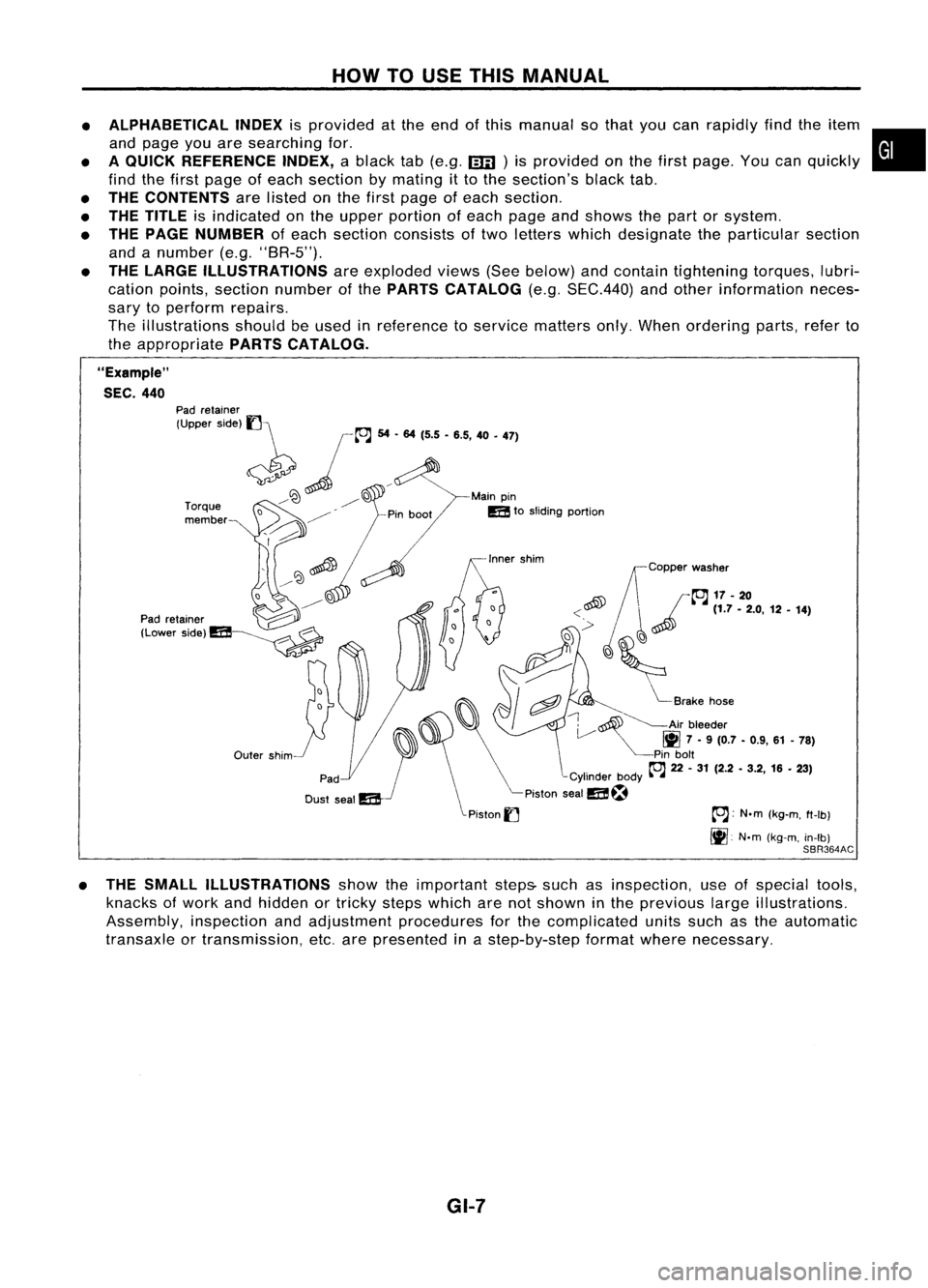
THE LARGE ILLUSTRATIONS areexploded views(Seebelow) andcontain tightening torques,lubri-
cation points, section number ofthe PARTS CATALOG (e.g.SEC.440) andother information neces-
sary toperform repairs.
The illustrations shouldbeused inreference toservice matters only.When ordering parts,referto
the appropriate PARTSCATALOG.
"Example"
SEC. 440
~~Copper washer
~ /~17-20
<~ ~~
(1.7-2.0, 12•14)
,~
'(~
,
i"::
I
cftJ ~
Brake hose
~ ~Air bleeder
V
1111
7•9 (0.7 -0.9, 61-78)
Pin bolt
~ 22-31 (2.2 -3.2, 16•23)
-Cylinder body~-~
Piston sealm~
Piston
I] ~:
N.m(kg-m, ft-Ib)
It].
N'm(kg-m, in-Ib)
SBR364AC
Outer
shim
Torque
member
Pad
retainer
(Upper side)
1]\
~ jL"J
54... 1'5•'.5, 40•
'71
/~ ~D Mainpin
/ mtosliding portion
o ~
D
~ ~
----------
Pad retainer ~
(Lower Side)m~
• THE SMALL ILLUSTRATIONS showtheimportant steps-suchasinspection, useofspecial tools,
knacks ofwork andhidden ortricky stepswhich arenotshown inthe previous largeillustrations.
Assembly, inspectionandadjustment procedures forthe complicated unitssuchasthe automatic
transaxle ortransmission, etc.arepresented inastep-by-step formatwherenecessary.
GI-7
Page 1362 of 1701
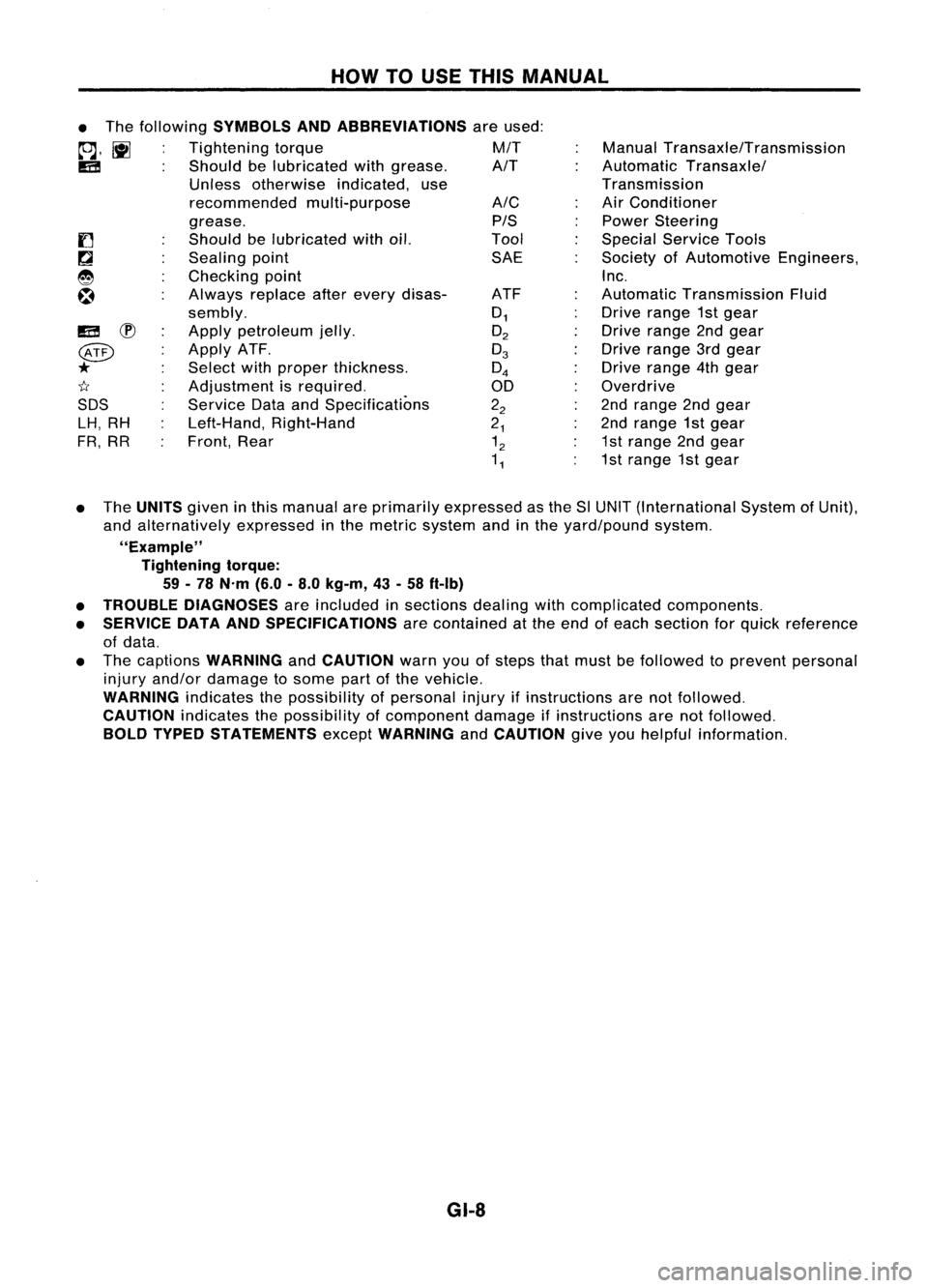
HOWTOUSE THIS MANUAL
ManualTransaxle/Transmission
Automatic Transaxle/
Transmission
Air Conditioner
Power Steering
Special Service Tools
Society ofAutomotive Engineers,
Inc.
Automatic Transmission Fluid
Drive range 1stgear
Drive range 2ndgear
Drive range 3rdgear
Drive range 4thgear
Overdrive
2nd range 2ndgear
2nd range 1stgear
1st range 2ndgear
1st range 1stgear
A/C
PIS
Tool SAE
ATF
0
1
O
2
0
3
0
4
00
2
2
2
1
1
2
1
1
•
The following
SYMBOLS ANDABBREVIATIONS
areused:
to;J,
l\tI
Tightening torque M/T
IE!
Shouldbelubricated withgrease. A/T
Unless otherwise indicated,use
recommended multi-purpose
grease.
Should belubricated withoil.
Sealing point
Checking point
Always replaceafterevery disas-
sembly.
Apply petroleum jelly.
Apply ATF.
Select withproper thickness.
Adjustment isrequired.
Service DataandSpecifications
Left-Hand, Right-Hand
Front, Rear
IE!
~
@
*
1I
SDS LH, RH
FR, RR
• The
UNITS
giveninthis manual areprimarily expressed asthe SlUNIT (International SystemofUnit),
and alternatively expressedinthe metric system andinthe yard/pound system.
"Example" Tightening torque:
59 -78 N'm (6.0-8.0 kg-m, 43-58 ft-Ib)
• TROUBLE DIAGNOSES
areincluded insections dealingwithcomplicated components.
• SERVICE DATAANDSPECIFICATIONS
arecontained atthe end ofeach section forquick reference
of data.
• The captions
WARNING
and
CAUTION
warnyouofsteps thatmust befollowed toprevent personal
injury and/or damage tosome partofthe vehicle.
WARNING
indicatesthepossibility ofpersonal injuryifinstructions arenotfollowed.
CAUTION
indicatesthepossibility ofcomponent damageifinstructions arenotfollowed.
BOLD TYPED STATEMENTS
except
WARNING
and
CAUTION
giveyouhelpful information.
GI-8