1995 JEEP YJ U Joint
[x] Cancel search: U JointPage 21 of 2158
CLASSIFICATION OF LUBRICANTS
Lubricating fluids and chassis lubricants are clas-
sified according to standards recommended by the:
²Society of Automotive Engineers (SAE)
²American Petroleum Institute (API)
²National Lubricating Grease Institute (NLGI)
ENGINE OIL
API CERTIFICATION MARK
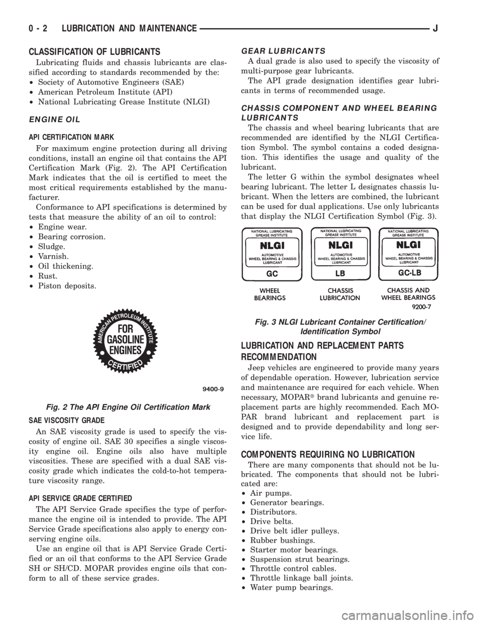
For maximum engine protection during all driving
conditions, install an engine oil that contains the API
Certification Mark (Fig. 2). The API Certification
Mark indicates that the oil is certified to meet the
most critical requirements established by the manu-
facturer.
Conformance to API specifications is determined by
tests that measure the ability of an oil to control:
²Engine wear.
²Bearing corrosion.
²Sludge.
²Varnish.
²Oil thickening.
²Rust.
²Piston deposits.
SAE VISCOSITY GRADE
An SAE viscosity grade is used to specify the vis-
cosity of engine oil. SAE 30 specifies a single viscos-
ity engine oil. Engine oils also have multiple
viscosities. These are specified with a dual SAE vis-
cosity grade which indicates the cold-to-hot tempera-
ture viscosity range.
API SERVICE GRADE CERTIFIED
The API Service Grade specifies the type of perfor-
mance the engine oil is intended to provide. The API
Service Grade specifications also apply to energy con-
serving engine oils.
Use an engine oil that is API Service Grade Certi-
fied or an oil that conforms to the API Service Grade
SH or SH/CD. MOPAR provides engine oils that con-
form to all of these service grades.
GEAR LUBRICANTS
A dual grade is also used to specify the viscosity of
multi-purpose gear lubricants.
The API grade designation identifies gear lubri-
cants in terms of recommended usage.
CHASSIS COMPONENT AND WHEEL BEARING
LUBRICANTS
The chassis and wheel bearing lubricants that are
recommended are identified by the NLGI Certifica-
tion Symbol. The symbol contains a coded designa-
tion. This identifies the usage and quality of the
lubricant.
The letter G within the symbol designates wheel
bearing lubricant. The letter L designates chassis lu-
bricant. When the letters are combined, the lubricant
can be used for dual applications. Use only lubricants
that display the NLGI Certification Symbol (Fig. 3).
LUBRICATION AND REPLACEMENT PARTS
RECOMMENDATION
Jeep vehicles are engineered to provide many years
of dependable operation. However, lubrication service
and maintenance are required for each vehicle. When
necessary, MOPARtbrand lubricants and genuine re-
placement parts are highly recommended. Each MO-
PAR brand lubricant and replacement part is
designed and to provide dependability and long ser-
vice life.
COMPONENTS REQUIRING NO LUBRICATION
There are many components that should not be lu-
bricated. The components that should not be lubri-
cated are:
²Air pumps.
²Generator bearings.
²Distributors.
²Drive belts.
²Drive belt idler pulleys.
²Rubber bushings.
²Starter motor bearings.
²Suspension strut bearings.
²Throttle control cables.
²Throttle linkage ball joints.
²Water pump bearings.
Fig. 2 The API Engine Oil Certification Mark
Fig. 3 NLGI Lubricant Container Certification/
Identification Symbol
0 - 2 LUBRICATION AND MAINTENANCEJ
Page 23 of 2158

MAINTENANCE SCHEDULES
INTRODUCTION
There are two maintenance schedules that show
proper service intervals for Jeep Cherokee and Jeep
Wrangler vehicles. Use the schedule that best de-
scribes the conditions the vehicle is operated under.
When mileage and time is listed, follow the interval
that occurs first.
ScheduleÐAlists all the scheduled maintenance
to be performed under normal operating conditions.
ScheduleÐBis a schedule for vehicles that are
usually operated under one or more of the following
conditions.
²Frequent short trip driving less than 5 miles (8
km).
²Frequent driving in dusty conditions.
²Trailer towing or heavy load hauling.
²Frequent long periods of engine idling.
²Sustained high speed operation.
²Desert operation.
²Frequent starting and stopping.
²Cold climate operation.
²Off road driving.
²Commercial service.
²Snow plow operation.
²More than half of vehicle operation occurs in
heavy city traffic during hot weather (above 90É F).
AT EACH STOP FOR GASOLINE
²Check engine oil level and add as required.
²Check windshield washer solvent and add as re-
quired.
ONCE A MONTH
²Check tire pressure and look for unusual tire wear
or damage.
²Check fluid levels of coolant reservoir, brake mas-
ter cylinder, power steering and transmission. Add
fluid as required.
²Check all lights and other electrical items for cor-
rect operation.
²Inspect battery and clean and tighten terminals as
required.
²Check rubber seals on each side of the radiator for
proper fit.
AT EACH OIL CHANGE
²Inspect exhaust system.
²Inspect brake hoses.
²Rotate the tires at each oil change interval shown
on ScheduleÐA: (7,500 Miles) or every other interval
shown on ScheduleÐB: (6,000 Miles).
²Check engine coolant level, hoses, and clamps.
²Lubricate 4x4 steering linkage.
²Lubricate propeller shaft universal joints and slip
spline, if equipped.After completion of off-road (4WD) operation, the
underside of the vehicle should be thoroughly in-
spected. Examine threaded fasteners for looseness.
HARSH SURFACE ENVIRONMENTS
After vehicle operation in a harsh surface environ-
ment, the following components should be inspected
and cleaned as soon as possible:
²Brake drums.
²Brake linings.
²Front wheel bearings (2WD vehicles only).
²Axle coupling joints.
This will prevent wear and/or unpredictable brake
action.
EMISSION CONTROL SYSTEM MAINTENANCE
The schedule emission maintenance listed inbold
typeon the following schedules, must be done at the
mileage specified to assure the continued proper
functioning of the emission control system. These,
and all other maintenance services included in this
manual, should be done to provide the best vehicle
performance and reliability. More frequent mainte-
nance may be needed for vehicles in severe operating
conditions such as dusty areas and very short trip
driving.
SCHEDULEÐA
7,500 MILES (12 000 KM) OR AT 6 MONTHS
²Change engine oil.
²Replace engine oil filter.
²Lubricate steering linkage (4x4).
15,000 MILES (24 000 KM) OR AT 12 MONTHS
²Change engine oil.
²Replace engine oil filter.
²Lubricate steering linkage.
22,500 MILES (36 000 KM) OR AT 18 MONTHS
²Change engine oil.
²Replace engine oil filter.
²Lubricate steering linkage (4x4).
²Inspect brake linings.
30,000 MILES (48 000 KM) OR AT 24 MONTHS
²Replace air cleaner element.
²Replace spark plugs.
²Adjust belt tension on non-automatic tensioning
drive belts.
²Change engine oil.
²Replace engine oil filter.
²Lubricate steering linkage.
²Drain and refill automatic transmission.
²Drain and refill transfer case.
0 - 4 LUBRICATION AND MAINTENANCEJ
Page 25 of 2158

SCHEDULEÐB
3,000 MILES (4 800KM)
²Change engine oil.
²Replace engine oil filter.
6,000 MILES (9 600KM)
²Change engine oil.
²Replace engine oil filter.
²Lubricate steering linkage (4x4).
9,000 MILES (14 400KM)
²Change engine oil.
²Replace engine oil filter.
12,000 MILES (19 200KM)
²Change engine oil.
²Replace engine oil filter.
²Drain and refill automatic transmission.
²Change front and rear axle fluid.*
²Lubricate steering linkage (4x4).
²Inspect brake linings.
15,000 MILES (24 000KM)
²Change engine oil.
²Replace engine oil filter.
²Lubricate steering linkage (4x2).
²Inspect air cleaner element, replace as necessary.
18,000 MILES (29 000KM)
²Change engine oil.
²Replace engine oil filter.
²Drain and refill Manual transmission fluid.
²Lubricate steering linkage (4x4).
21,000 MILES (34 000KM)
²Change engine oil.
²Replace engine oil filter.
24,000 MILES (38 000KM)
²Change engine oil.
²Replace engine oil filter.
²Lubricate steering linkage (4x4).
²Drain and refill automatic transmission.
²Change front and rear axle fluid.*
²Inspect brake linings.
²Inspect front wheel bearings, Clean and repack if
required (4x2).
27,000 MILES (43 000KM)
²Change engine oil.
²Replace engine oil filter.
30,000 MILES (48 000KM)
²Change engine oil.
²Replace engine oil filter.
²Lubricate steering linkage joints.
²Replace spark plugs.
²Replace air cleaner element.²Adjust drive belts.
²Drain and refill transfer case fluid.
33,000 MILES (53 000KM)
²Change engine oil.
²Replace engine oil filter.
36,000 MILES (58 000KM)
²Change engine oil.
²Replace engine oil filter.
²Lubricate steering linkage (4x4).
²Drain and refill automatic transmission.
²Drain and refill manual transmission fluid.
²Change front and rear axle fluid.*
²Inspect brake linings.
39,000 MILES (62 000KM)
²Change engine oil.
²Replace engine oil filter.
42,000 MILES (67 000KM)
²Change engine oil.
²Replace engine oil filter.
²Lubricate steering linkage (4x4).
45,000 MILES (72 000KM)
²Change engine oil.
²Replace engine oil filter.
²Lubricate steering linkage (4x2).
²Inspect air cleaner element, replace as necessary.
48,000 MILES (77 000KM)
²Change engine oil.
²Replace engine oil filter.
²Lubricate steering linkage (4x4).
²Drain and refill automatic transmission.
²Change front and rear axle fluid.*
²Inspect brake linings.
51,000 MILES (82 000KM)
²Change engine oil.
²Replace engine oil filter.
²Flush and replace engine coolant.
54,000 MILES (86 400KM)
²Change engine oil.
²Replace engine oil filter.
²Lubricate steering linkage (4x4).
²Drain and refill Manual transmission fluid.
57,000 MILES (91 000KM)
²Change engine oil.
²Replace engine oil filter.
60,000 MILES (96 000KM)
²Change engine oil.
²Replace engine oil filter.
²Lubricate steering linkage joints.
²Replace spark plugs.
0 - 6 LUBRICATION AND MAINTENANCEJ
Page 32 of 2158

4WD YJ VEHICLES
(1) Raise the rear of the vehicle off the ground and
install tow dollies under rear wheels.
CAUTION: Use tow chains with T-hooks for con-
necting to the disabled vehicle's frame rails. Never
use J-hooks.
(2) Attach the T-hooks to the slots in the front end
of each frame rail (Fig. 7).
(3) Position each safety chain over the top of each
front spring and inboard of each front spring shackle.
(4) Double wrap each chain.
(5) Position the sling crossbar under the front
bumper.
(6) Turn the ignition switch to the OFF position to
unlock the steering wheel.
(7) Shift the transfer case to NEUTRAL.
TOWING WHEN KEYS ARE NOT AVAILABLE
When the vehicle is locked and keys are not avail-
able, use a flat bed hauler. A Wheel-lift or Sling-type
device can be used provided all the wheels are lifted
off the ground using tow dollies (Fig. 8).
EMERGENCY TOW HOOKS
WARNING: REMAIN AT A SAFE DISTANCE FROM A
VEHICLE THAT IS BEING TOWED VIA ITS TOW
HOOKS. THE TOW STRAPS/CHAINS COULD BREAK
AND CAUSE SERIOUS INJURY.
Some Jeep vehicles are equipped with front and
rear emergency tow hooks (Fig. 9). The tow hooks
should be used forEMERGENCYpurposes only.CAUTION: DO NOT use emergency tow hooks for
tow truck hook-up or highway towing.
FLAT TOWING (4 TIRES/WHEELS ON
SURFACE)
Tow a vehicle in this manner only when all four
wheels will freely rotate. Prepare the vehicle accord-
ing to the following procedures.
2WD VEHICLES
(1) Mark the drive shaft and the axle drive pinion
gear shaft yoke for installation alignment reference.
(2) Remove the drive shaft. Install a protective cov-
ering over the drive shaft U-joints to retain them as-
sembled and protected.
Fig. 7 Sling-Type, Front-End Towing (YJ Vehicles)
Fig. 8 Sling-Type, Front-End Towing With Rear
Wheels On A Tow Dolly
Fig. 9 Emergency Front Tow HooksÐXJ & YJ
Vehicles
JLUBRICATION AND MAINTENANCE 0 - 13
Page 40 of 2158

ENGINE SUPPORTS
The general condition of the engine supports
should be inspected when engine compartment or un-
der vehicle service is performed.
INSPECTION
(1) Test the hardware that attaches the engine cyl-
inder block to the engine support brackets (Figs. 11
and 12) for the specified tightening torque.(2) Inspect the rubber in the engine support cush-
ions for softening and swelling. Slight surface deteri-
oration and wear at the ends will not affect the
functioning of an engine support.
ACCESSORY DRIVE BELT
Inspect and adjust drive belts at the interval de-
scribed in the Lubrication and Maintenance Sched-
ules. Refer to General Information section of this
group. For proper inspection and adjustment proce-
dures, see Group 7, Cooling System.
EXHAUST SYSTEM
The exhaust system should be inspected when un-
der vehicle service is performed or as specified in the
Lubrication and Maintenance Schedules.
INSPECTION
When inspecting an exhaust system, inspect for
cracked or loose joints, stripped screw/bolt threads,
corrosion damage, and worn or broken hangers
(Slight cracking in rubber isolator or hanger is ac-
ceptable). Replace all components that are corroded
or damaged. Do not attempt repair. Also, inspect for
the following obvious conditions and correct as neces-
sary:
²Exhaust system leaks, damage, misalignment.
²Contact with body panels metal or the frame.
²Catalytic converter bulging or excessive heat dam-
age.
CAUTION: A catalytic converter will become con-
taminated if leaded gasoline is burned in the en-
gine. If this occurs, the complete converter must be
replaced.
For proper service procedures see Group 11, Ex-
haust System and Intake Manifold.
AIR-CONDITIONER COMPRESSOR
LUBRICANT AND REFRIGERANT
The lubricant level in the air-conditioner compres-
sor should be checked if there are indications that oil
was lost. Loss of lubricating oil usually accompanies
a loss of refrigerant.
For additional information involving the A/C sys-
tem, refer to Group 24, Heater And Air Conditioning.
Fig. 11 Front Engine SupportÐTypical
Fig. 12 Rear Engine SupportÐTypical
JLUBRICATION AND MAINTENANCE 0 - 21
Page 71 of 2158

Axle shaft bearings produce noise and vibration
when worn or damaged. The noise generally changes
when the bearings are loaded. Road test the vehicle.
Turn the vehicle sharply to the left and to the right.
This will load the bearings and change the noise
level. Where axle bearing damage is slight, the noise
is usually not noticeable at speeds above 30 mph.
LOW SPEED KNOCK
Low speed knock is generally caused by a worn U-
joint or by worn side-gear thrust washers. A worn
pinion gear shaft bore will also cause low speed
knock.
VIBRATION
Vibration at the rear of the vehicle is usually
caused by a:
²Damaged drive shaft
²Missing drive shaft balance weight
²Worn, out-of-balance wheels
²Loose wheel lug nuts
²Worn U-joint
²Loose spring U-bolts
²Loose/broken springs
²Damaged axle shaft bearings
²Loose pinion gear nut
²Excessive pinion yoke run out²Bent axle shaft
Check for loose or damaged front-end components
or engine/transmission mounts. These components
can contribute to what appears to be a rear-end vi-
bration. Do not overlook engine accessories, brackets
and drive belts.
All driveline components should be examined be-
fore starting any repair.
Refer to Group 22ÐTires And Wheels for addi-
tional information involving vibration diagnosis.
DRIVELINE SNAP
A snap or clunk noise when the vehicle is shifted
into gear (or the clutch engaged), can be caused by:
²High engine idle speed
²Loose engine/transmission/transfer case mounts
²Worn U-joints
²Loose spring mounts
²Loose pinion gear nut and yoke
²Excessive ring gear backlash
²Excessive differential side gear-to-case clearance
The source of a snap or a clunk noise can be deter-
mined with the assistance of a helper. Raise the ve-
hicle on a hoist with the wheels free to rotate.
Instruct the helper to shift the transmission into
gear. Listen for the noise, a mechanics stethoscope is
helpful in isolating the source of a noise.
JFRONT SUSPENSION AND AXLE 2 - 19
Page 74 of 2158

MODEL 30 AXLE AND TUBE AXLE (2WD)
INDEX
page page
Axle Bushing Replacement.................. 34
Axle ShaftÐCardan U-Joint.................. 26
Backlash and Contact Pattern Analysis......... 45
Cleaning/Inspection........................ 37
Differential and Pinion Measurement........... 40
Differential Assembly....................... 38
Differential Disassembly.................... 35
Differential Installation...................... 44
Differential Removal....................... 34
Differential Shim Pack Measurement and
Adjustment............................ 43
Drive Axle Assembly ReplacementÐXJ Vehicles . . 23
Drive Axle Assembly ReplacementÐYJ Vehicles . . 24Final Assembly........................... 46
Hub Bearing and Axle Shaft................. 25
Information.............................. 22
Inner Axle Shaft Oil Seal Replacement......... 35
Lubricant Change......................... 23
Lubricant Specifications..................... 22
Pinion Gear Assembly/Installation............. 42
Pinion Gear Depth Information............... 39
Pinion Removal/Disassembly................. 36
Pinion Seal Replacement................... 25
Steering Knuckle and Ball Studs.............. 32
Vacuum Disconnect AxleÐYJ Vehicles......... 27
INFORMATION
The Model 30 front axles consists of a cast iron dif-
ferential housing with axle shaft tubes extending
from either side. The tubes are pressed into the dif-
ferential housing and welded.
The integral type housing, hypoid gear design has
the centerline of the pinion set above the centerline
of the ring gear.
The axle has a fitting for a vent hose used to re-
lieve internal pressure caused by lubricant vaporiza-
tion and internal expansion.
The axles are equipped with semi-floating axle
shafts, meaning that loads are supported by the hub
bearings. The axle shafts are retained by nuts at the
hub bearings. The hub bearings are bolted to the
steering knuckle at the outboard end of the axle tube
yoke. The hub bearings are serviced as an assembly.
The axles are equipped with ABS brake sensors.
The sensors are attached to the knuckle assemblies
and tone rings are pressed on the axle shaft.Use
care when removing axle shafts as NOT to dam-
age the tone wheel or the sensor.
The stamped steel cover provides a means for in-
spection and servicing the differential.
The Model 30 axle has the assembly part number
and gear ratio listed on a tag. The tag is attached to
the housing cover. Build date identification codes are
stamped on the axle shaft tube cover side.
The differential case is a one-piece design. The dif-
ferential pinion mate shaft is retained with a roll
pin. Differential bearing preload and ring gear back-
lash is adjusted by the use of shims (select thick-
ness). The shims are located between the differential
bearing cones and case. Pinion bearing preload is set
and maintained by the use of collapsible spacer.
COMMAND-TRACÐYJ VEHICLES
The Command-Trac system is a vacuum disconnect
axle. The system has a two-piece axle shaft coupled
together by a shift collar. For two-wheel drive opera-
tion, the vacuum motor and shift fork disengages the
axle shaft splines. For four-wheel drive operation, the
vacuum motor and shift fork engages the axle
splines.
SELEC-TRACÐXJ VEHICLES
The Selec-Trac system is a non-disconnect axle.
Shifting from two-wheel to four-wheel drive is done
at the transfer case.
For XJ vehicles equipped withSelec-Tracand
ABS brake system, refer to Group 5ÐBrakes for ad-
ditional service information.
LUBRICANT SPECIFICATIONS
Multi-purpose, hypoid gear lubricant should be
used for Model 30 axles. The lubricant should have
MIL-L-2105C and API GL 5 quality specifications.
MOPARtHypoid Gear Lubricant conforms to both of
these specifications.
²The factory fill for the Model 30 axle is SAE Ther-
mally Stable 80W-90 gear lubricant.Do not use
heavier weight lubricant, this will cause axle
engagement difficulties.
²The factory installed lubricant quantity for the
NON-DISCONNECT TYPE AXLE is 1.48 L (3.13
pts.).
²The factory installed lubricant quantity for the
VACUUM-DISCONNECT TYPE AXLE is 1.65 L (3.76
pts.).
Refer to Group 0, Lubrication and Maintenance for
additional information regarding temperature range,
viscosity and fluid level.
2 - 22 FRONT SUSPENSION AND AXLEJ
Page 76 of 2158

(6) Install the shock absorber and tighten the bolt
to 23 Nzm (17 ft. lbs.) torque.
(7) Install the stabilizer bar link to the axle
bracket. Tighten the nut to 95 Nzm (70 ft. lbs.)
torque.
(8) Install the drag link and tie rod to the steering
knuckles and tighten the nuts to 47 Nzm (35 ft. lbs.)
torque. Install the steering damper to the axle
bracket and tighten the nut to 75 Nzm (55 ft. lbs.)
torque.
(9) Install the brake components and ABS brake
sensor (if equipped). Refer to Group 5ÐBrakes.
(10) On 4WD vehicles, connect the vent hose to the
tube fitting.
(11) On 4WD vehicles, align the reference marks
and connect the drive shaft to the axle yoke. Tighten
the U-joint clamp bolts to 19 Nzm (14 ft. lbs.) torque.
(12) Check differential lubricant and add if neces-
sary.
(13) Install the wheel and tire assemblies.
(14) Remove the supports and lower the vehicle.
(15) Tighten the upper suspension arm nuts to 75
Nzm (55 ft. lbs.) torque. Tighten the lower suspension
arm nuts to 115 Nzm (85 ft. lbs.) torque.
(16) Tighten the track bar bolt at the axle bracket
to 100 Nzm (74 ft. lbs.) torque.
(17) Check the front wheel alignment.
DRIVE AXLE ASSEMBLY REPLACEMENTÐYJ
VEHICLES
REMOVAL
(1) Raise the vehicle and position support stands
under the frame rails behind the spring frame brack-
ets.
(2) Remove the front wheels.
(3) Remove the brake components and ABS brake
sensor (if equipped). Refer to Group 5ÐBrakes.
(4) Disconnect the axle vent hose and axle shift
motor vacuum harness.
(5) Mark the drive shaft yoke and axle pinion yoke
for alignment reference. Disconnect the drive shaft
from the axle.
(6) Disconnect the stabilizer bar link at the axle
bracket.
(7) Disconnect the shock absorbers from axle
bracket.
(8) Disconnect the track bar from the axle bracket.
(9) Disconnect the tie rod from the steering
knuckle. Disconnect the steering damper from the
axle bracket.
(10) Support the axle with a hydraulic jack under
the differential. Raise the axle just enough to relieve
the axle weight from the springs.
(11) Remove the spring U-bolts from the plate
brackets.(12) Loosen BUT DO NOT REMOVE the bolts that
attach the spring rear pivot at the frame rail brack-
ets. This will allow the springs to pivot without bind-
ing on the bushings.
(13) Disconnect shackle from the springs and lower
the springs to the surface.
(14) Lower the jack enough to remove the axle.
INSTALLATION
CAUTION: Suspension components with rubber
bushings should be tightened with the vehicle at
normal height. It is important to have the springs
supporting the weight of the vehicle when the fas-
teners are torqued. If springs are not at their normal
ride position, vehicle ride comfort could be affected
and premature bushing wear may occur. Rubber
bushings must never be lubricated.
(1) Support the axle on a hydraulic jack under the
differential. Position the axle under the vehicle.
(2) Raise the springs and install the spring shackle
bolts.Do not tighten at this time.
(3) Lower the axle and align the spring center
bolts with the locating holes in the axle pads and
plate brackets.
(4) Install the spring U-bolts through the plate
brackets and tighten to 122 Nzm (90 ft. lbs.) torque.
(5) Connect the track bar to the axle bracket and
install the bolt.Do not tighten at this time.
It is important that the springs support the
weight of the vehicle when the track bar is con-
nected. If springs are not at their usual posi-
tion, the vehicle ride comfort could be affected.
(6) Install the shock absorber and tighten the nut
to 61 Nzm (45 ft. lbs.) torque.
(7) Install the stabilizer bar link to the axle
bracket. Tighten the nut to 61 Nzm (45 ft. lbs.)
torque.
(8) Install the tie rod to the steering knuckles and
tighten the nuts to 47 Nzm (35 ft. lbs.) torque. Install
the steering damper to the axle bracket and tighten
the bolt to 75 Nzm (55 ft. lbs.) torque.
(9) Install the brake components and ABS brake
sensor (if equipped). Refer to Group 5ÐBrakes.
(10) Connect the vent hose to the tube fitting and
axle shift motor vacuum harness.
(11) Align the reference marks and connect the
drive shaft to the axle yoke. Tighten the U-joint
clamp bolts to 19 Nzm (14 ft. lbs.) torque.
(12) Check differential lubricant and add if neces-
sary.
(13) Install the wheel and tire assemblies.
(15) Remove the supports and lower the vehicle.
(16) Tighten the spring rear pivot bolt/nut to 142
Nzm (105 ft. lbs.) torque. Tighten the spring shackle
bolt/nut to 135 Nzm (100 ft. lbs.) torque.
2 - 24 FRONT SUSPENSION AND AXLEJ