1995 JEEP YJ U Joint
[x] Cancel search: U JointPage 1398 of 2158
The frame is constructed of high-strength channel
steel siderails and crossmembers. The crossmembers
join the siderails and retain them in alignment in re-
lation to each other. This provides resistance to
frame twists and strains.
FRAME STRAIGHTENING
When necessary, a conventional frame that is bent
or twisted can be straightened by application of heat.
The temperature must not exceed 566ÉC (1050ÉF).
The use of a specially designed heat crayon can de-
termine the desired temperature. Excessive heat will
decrease the strength of the metal and result in a
weakened frame.
Welding the joints around riveted cross members
and frame side rails is not recommended.
A straightening repair process should be limited to
frame members that are not severely damaged.
FRAME REPAIRS
DRILLING HOLES
Do not drill holes in frame side rail top and bottom
flanges, metal fatigue can result causing frame fail-
ure. Holes drilled in the side of the frame rail must
be at least 38 mm (1.5 in.) from the top and bottom
flanges.
Additional drill holes should be located away from
existing holes.
WELDING
Use MIG, TIG or arc welding equipment to repair
welded frame components.
Frame components that have been damaged should
be inspected for cracks before returning the vehicle
to use. If cracks are found in accessible frame com-
ponents perform the following procedures.
(1) Drill a hole at each end of the crack with a 3
mm (O.125 in.) diameter drill bit.
(2) Using a suitable die grinder with 3 inch cut off
wheel, V-groove the crack to allow 100% weld pene-
tration.
(3) Weld the crack.
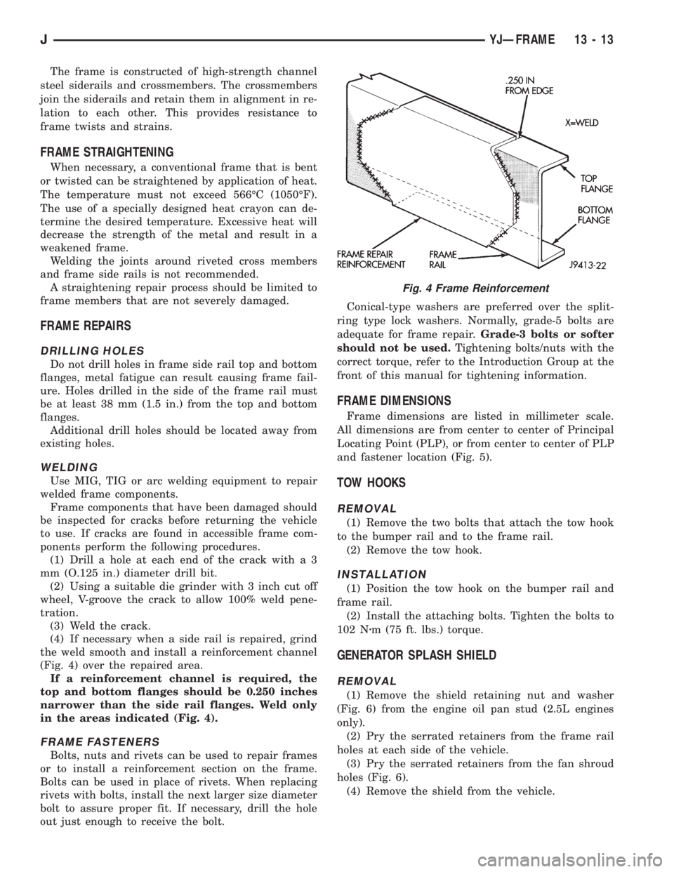
(4) If necessary when a side rail is repaired, grind
the weld smooth and install a reinforcement channel
(Fig. 4) over the repaired area.
If a reinforcement channel is required, the
top and bottom flanges should be 0.250 inches
narrower than the side rail flanges. Weld only
in the areas indicated (Fig. 4).
FRAME FASTENERS
Bolts, nuts and rivets can be used to repair frames
or to install a reinforcement section on the frame.
Bolts can be used in place of rivets. When replacing
rivets with bolts, install the next larger size diameter
bolt to assure proper fit. If necessary, drill the hole
out just enough to receive the bolt.Conical-type washers are preferred over the split-
ring type lock washers. Normally, grade-5 bolts are
adequate for frame repair.Grade-3 bolts or softer
should not be used.Tightening bolts/nuts with the
correct torque, refer to the Introduction Group at the
front of this manual for tightening information.
FRAME DIMENSIONS
Frame dimensions are listed in millimeter scale.
All dimensions are from center to center of Principal
Locating Point (PLP), or from center to center of PLP
and fastener location (Fig. 5).
TOW HOOKS
REMOVAL
(1) Remove the two bolts that attach the tow hook
to the bumper rail and to the frame rail.
(2) Remove the tow hook.
INSTALLATION
(1) Position the tow hook on the bumper rail and
frame rail.
(2) Install the attaching bolts. Tighten the bolts to
102 Nzm (75 ft. lbs.) torque.
GENERATOR SPLASH SHIELD
REMOVAL
(1) Remove the shield retaining nut and washer
(Fig. 6) from the engine oil pan stud (2.5L engines
only).
(2) Pry the serrated retainers from the frame rail
holes at each side of the vehicle.
(3) Pry the serrated retainers from the fan shroud
holes (Fig. 6).
(4) Remove the shield from the vehicle.
Fig. 4 Frame Reinforcement
JYJÐFRAME 13 - 13
Page 1470 of 2158
PROPELLER SHAFTS
CONTENTS
page page
GENERAL INFORMATION.................. 1
SERVICE DIAGNOSIS..................... 3
SERVICE PROCEDURES................... 8TORQUE SPECIFICATIONS................ 15
UNIVERSAL JOINT REPLACEMENT......... 10
GENERAL INFORMATION
PROPELLER SHAFTS
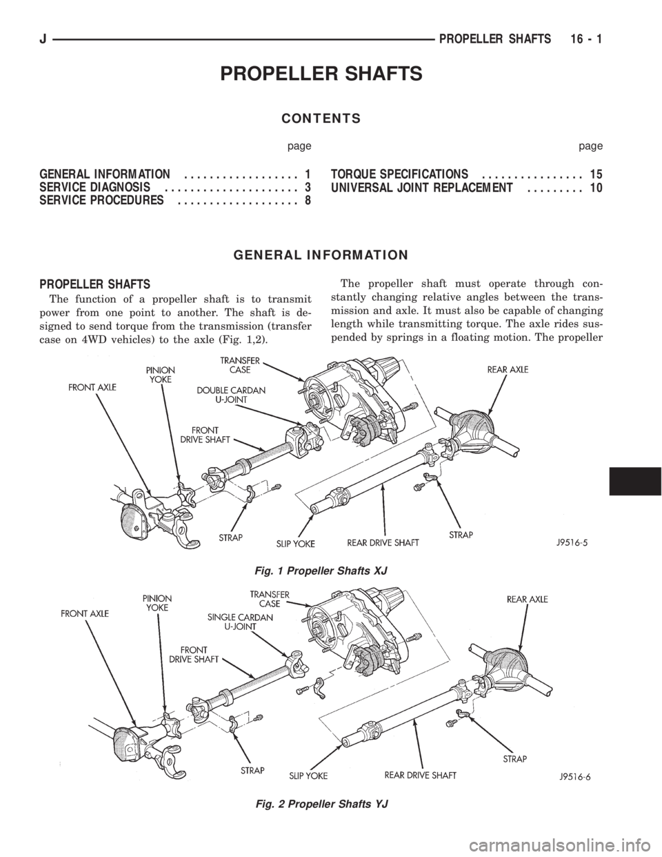
The function of a propeller shaft is to transmit
power from one point to another. The shaft is de-
signed to send torque from the transmission (transfer
case on 4WD vehicles) to the axle (Fig. 1,2).The propeller shaft must operate through con-
stantly changing relative angles between the trans-
mission and axle. It must also be capable of changing
length while transmitting torque. The axle rides sus-
pended by springs in a floating motion. The propeller
Fig. 1 Propeller Shafts XJ
Fig. 2 Propeller Shafts YJ
JPROPELLER SHAFTS 16 - 1
Page 1471 of 2158
shaft must be able to change operating angles when
going over various road surfaces. This is done
through universal joints, which permit the propeller
shaft to operate at different angles. The slip joints (or
yokes) permit contraction or expansion (Fig. 1,2).
Tubular propeller shafts are balanced by the man-
ufacturer with weights spot welded to the tube.
The propeller shaft is designed and built with the
yoke lugs in line with each other which is called
phasing. This design produces the smoothest running
condition, an out of phase shaft can cause a vibra-
tion.
Before undercoating a vehicle, the propeller
shaft and the U-joints should be covered. This
will prevent the undercoating from causing an
unbalanced condition and vibration.
CAUTION: Use exact replacement hardware for at-
taching the propeller shafts. The specified torque
must always be applied when tightening the fasten-
ers.
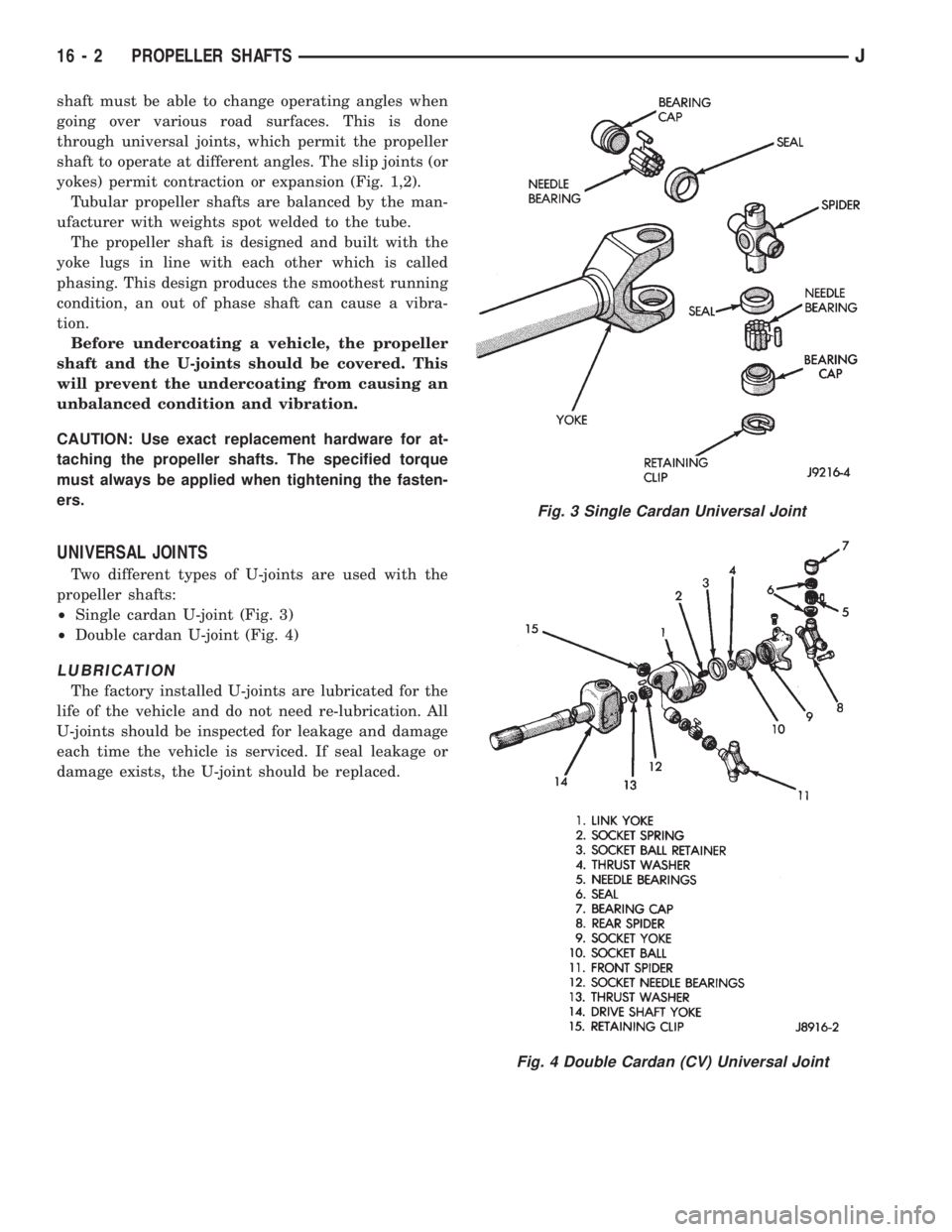
UNIVERSAL JOINTS
Two different types of U-joints are used with the
propeller shafts:
²Single cardan U-joint (Fig. 3)
²Double cardan U-joint (Fig. 4)
LUBRICATION
The factory installed U-joints are lubricated for the
life of the vehicle and do not need re-lubrication. All
U-joints should be inspected for leakage and damage
each time the vehicle is serviced. If seal leakage or
damage exists, the U-joint should be replaced.
Fig. 3 Single Cardan Universal Joint
Fig. 4 Double Cardan (CV) Universal Joint
16 - 2 PROPELLER SHAFTSJ
Page 1472 of 2158
SERVICE DIAGNOSIS
INDEX
page page
Runout.................................. 4
Unbalance............................... 3Universal Joint Angle Measurement............. 4
Vibration................................. 3
VIBRATION
Tires that are out-of-round or wheels that are un-
balanced will cause a low frequency vibration. Refer
to Group 22, Wheels and Tires for additional infor-
mation.
Brake drums that are unbalanced will cause a
harsh, low frequency vibration. Refer to Group 5,
Brakes for additional information.
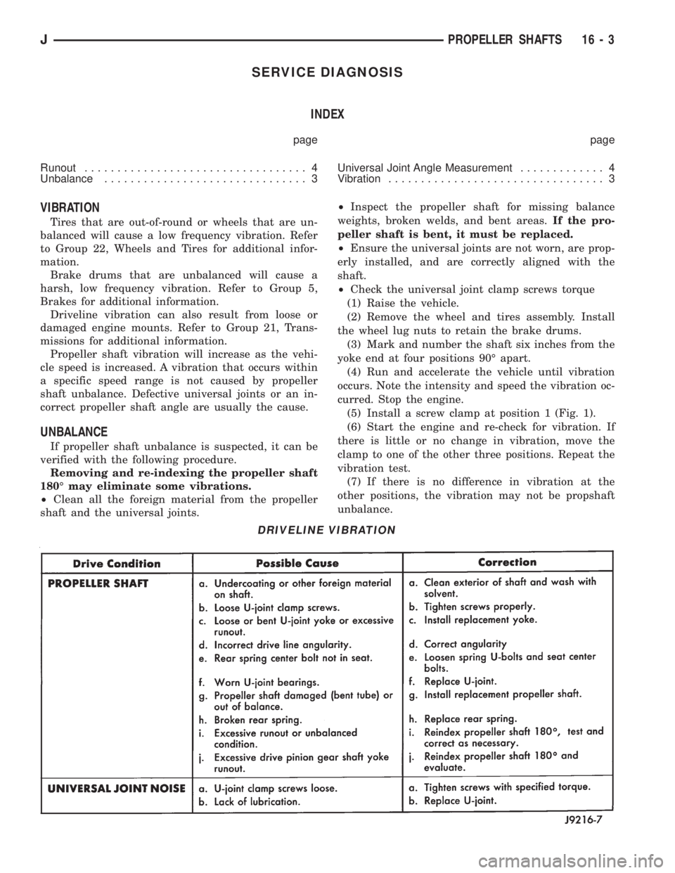
Driveline vibration can also result from loose or
damaged engine mounts. Refer to Group 21, Trans-
missions for additional information.
Propeller shaft vibration will increase as the vehi-
cle speed is increased. A vibration that occurs within
a specific speed range is not caused by propeller
shaft unbalance. Defective universal joints or an in-
correct propeller shaft angle are usually the cause.
UNBALANCE
If propeller shaft unbalance is suspected, it can be
verified with the following procedure.
Removing and re-indexing the propeller shaft
180É may eliminate some vibrations.
²Clean all the foreign material from the propeller
shaft and the universal joints.²Inspect the propeller shaft for missing balance
weights, broken welds, and bent areas.If the pro-
peller shaft is bent, it must be replaced.
²Ensure the universal joints are not worn, are prop-
erly installed, and are correctly aligned with the
shaft.
²Check the universal joint clamp screws torque
(1) Raise the vehicle.
(2) Remove the wheel and tires assembly. Install
the wheel lug nuts to retain the brake drums.
(3) Mark and number the shaft six inches from the
yoke end at four positions 90É apart.
(4) Run and accelerate the vehicle until vibration
occurs. Note the intensity and speed the vibration oc-
curred. Stop the engine.
(5) Install a screw clamp at position 1 (Fig. 1).
(6) Start the engine and re-check for vibration. If
there is little or no change in vibration, move the
clamp to one of the other three positions. Repeat the
vibration test.
(7) If there is no difference in vibration at the
other positions, the vibration may not be propshaft
unbalance.
DRIVELINE VIBRATION
JPROPELLER SHAFTS 16 - 3
Page 1473 of 2158
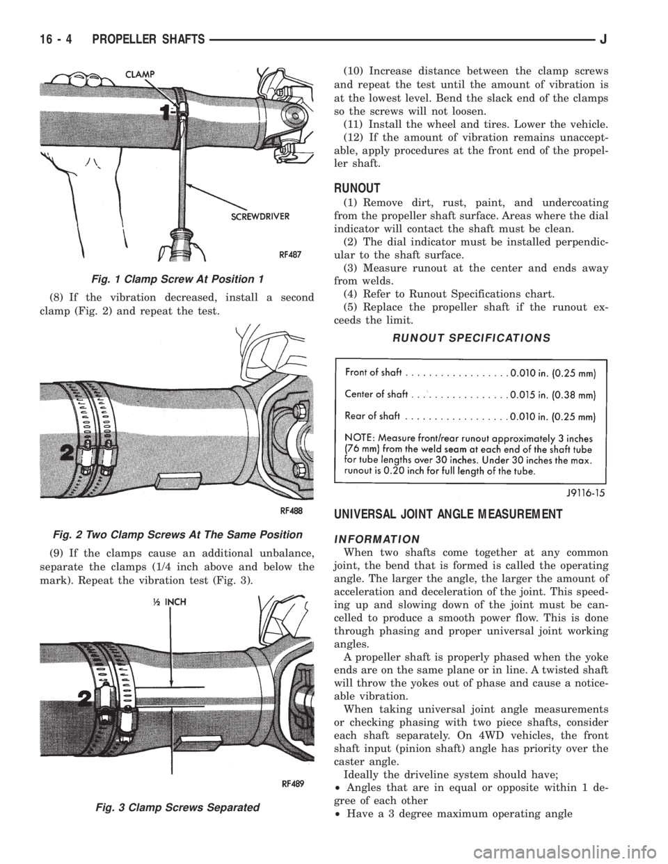
(8) If the vibration decreased, install a second
clamp (Fig. 2) and repeat the test.
(9) If the clamps cause an additional unbalance,
separate the clamps (1/4 inch above and below the
mark). Repeat the vibration test (Fig. 3).(10) Increase distance between the clamp screws
and repeat the test until the amount of vibration is
at the lowest level. Bend the slack end of the clamps
so the screws will not loosen.
(11) Install the wheel and tires. Lower the vehicle.
(12) If the amount of vibration remains unaccept-
able, apply procedures at the front end of the propel-
ler shaft.
RUNOUT
(1) Remove dirt, rust, paint, and undercoating
from the propeller shaft surface. Areas where the dial
indicator will contact the shaft must be clean.
(2) The dial indicator must be installed perpendic-
ular to the shaft surface.
(3) Measure runout at the center and ends away
from welds.
(4) Refer to Runout Specifications chart.
(5) Replace the propeller shaft if the runout ex-
ceeds the limit.
UNIVERSAL JOINT ANGLE MEASUREMENT
INFORMATION
When two shafts come together at any common
joint, the bend that is formed is called the operating
angle. The larger the angle, the larger the amount of
acceleration and deceleration of the joint. This speed-
ing up and slowing down of the joint must be can-
celled to produce a smooth power flow. This is done
through phasing and proper universal joint working
angles.
A propeller shaft is properly phased when the yoke
ends are on the same plane or in line. A twisted shaft
will throw the yokes out of phase and cause a notice-
able vibration.
When taking universal joint angle measurements
or checking phasing with two piece shafts, consider
each shaft separately. On 4WD vehicles, the front
shaft input (pinion shaft) angle has priority over the
caster angle.
Ideally the driveline system should have;
²Angles that are in equal or opposite within 1 de-
gree of each other
²Have a 3 degree maximum operating angle
Fig. 1 Clamp Screw At Position 1
Fig. 2 Two Clamp Screws At The Same Position
Fig. 3 Clamp Screws Separated
RUNOUT SPECIFICATIONS
16 - 4 PROPELLER SHAFTSJ
Page 1474 of 2158
²Have at least a 1/2 degree continuous operating
(propeller shaft) angle
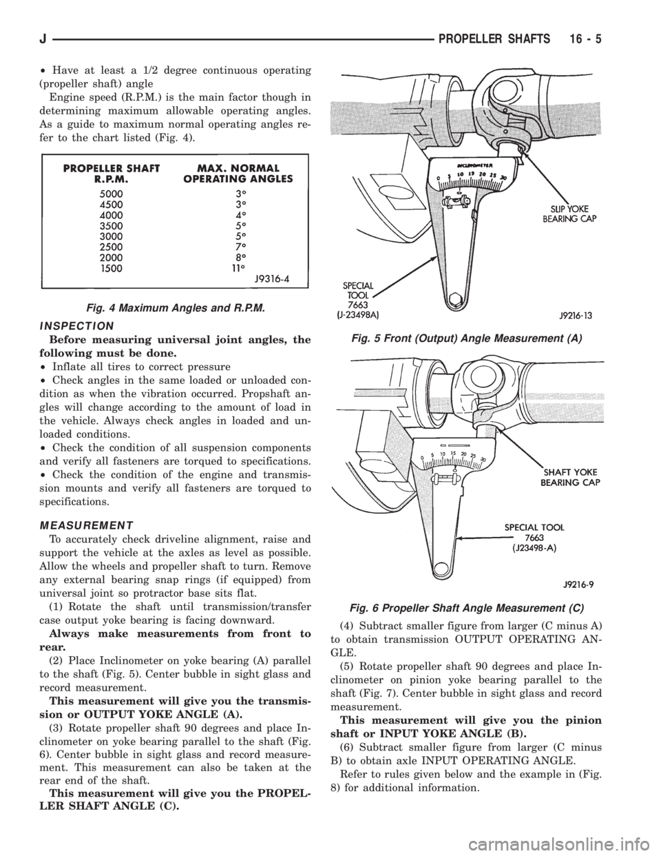
Engine speed (R.P.M.) is the main factor though in
determining maximum allowable operating angles.
As a guide to maximum normal operating angles re-
fer to the chart listed (Fig. 4).
INSPECTION
Before measuring universal joint angles, the
following must be done.
²Inflate all tires to correct pressure
²Check angles in the same loaded or unloaded con-
dition as when the vibration occurred. Propshaft an-
gles will change according to the amount of load in
the vehicle. Always check angles in loaded and un-
loaded conditions.
²Check the condition of all suspension components
and verify all fasteners are torqued to specifications.
²Check the condition of the engine and transmis-
sion mounts and verify all fasteners are torqued to
specifications.
MEASUREMENT
To accurately check driveline alignment, raise and
support the vehicle at the axles as level as possible.
Allow the wheels and propeller shaft to turn. Remove
any external bearing snap rings (if equipped) from
universal joint so protractor base sits flat.
(1) Rotate the shaft until transmission/transfer
case output yoke bearing is facing downward.
Always make measurements from front to
rear.
(2) Place Inclinometer on yoke bearing (A) parallel
to the shaft (Fig. 5). Center bubble in sight glass and
record measurement.
This measurement will give you the transmis-
sion or OUTPUT YOKE ANGLE (A).
(3) Rotate propeller shaft 90 degrees and place In-
clinometer on yoke bearing parallel to the shaft (Fig.
6). Center bubble in sight glass and record measure-
ment. This measurement can also be taken at the
rear end of the shaft.
This measurement will give you the PROPEL-
LER SHAFT ANGLE (C).(4) Subtract smaller figure from larger (C minus A)
to obtain transmission OUTPUT OPERATING AN-
GLE.
(5) Rotate propeller shaft 90 degrees and place In-
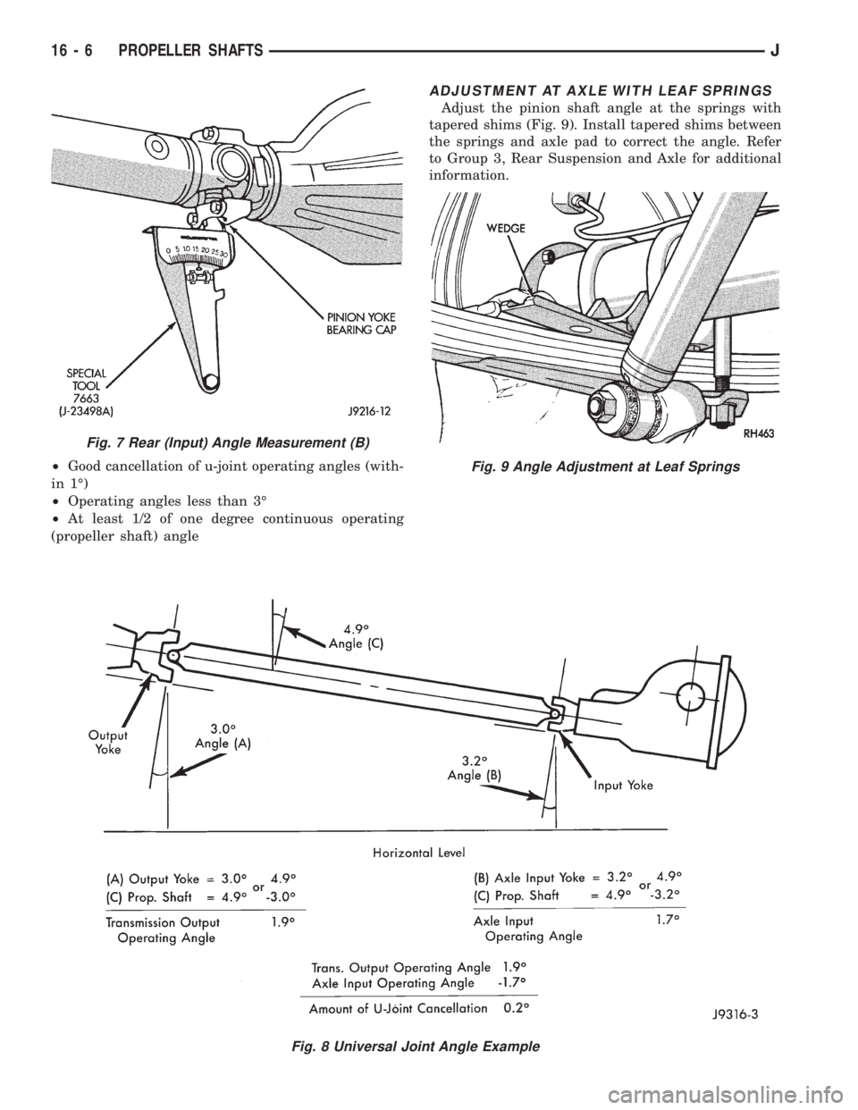
clinometer on pinion yoke bearing parallel to the
shaft (Fig. 7). Center bubble in sight glass and record
measurement.
This measurement will give you the pinion
shaft or INPUT YOKE ANGLE (B).
(6) Subtract smaller figure from larger (C minus
B) to obtain axle INPUT OPERATING ANGLE.
Refer to rules given below and the example in (Fig.
8) for additional information.
Fig. 4 Maximum Angles and R.P.M.
Fig. 5 Front (Output) Angle Measurement (A)
Fig. 6 Propeller Shaft Angle Measurement (C)
JPROPELLER SHAFTS 16 - 5
Page 1475 of 2158
²Good cancellation of u-joint operating angles (with-
in 1É)
²Operating angles less than 3É
²At least 1/2 of one degree continuous operating
(propeller shaft) angle
ADJUSTMENT AT AXLE WITH LEAF SPRINGS
Adjust the pinion shaft angle at the springs with
tapered shims (Fig. 9). Install tapered shims between
the springs and axle pad to correct the angle. Refer
to Group 3, Rear Suspension and Axle for additional
information.
Fig. 8 Universal Joint Angle Example
Fig. 7 Rear (Input) Angle Measurement (B)
Fig. 9 Angle Adjustment at Leaf Springs
16 - 6 PROPELLER SHAFTSJ
Page 1477 of 2158
SERVICE PROCEDURES
PRECAUTIONS
Use exact replacement hardware for attaching the
propeller shafts. Exact replacement will ensure safe
operation. The specified torque must always be ap-
plied when tightening the fasteners.
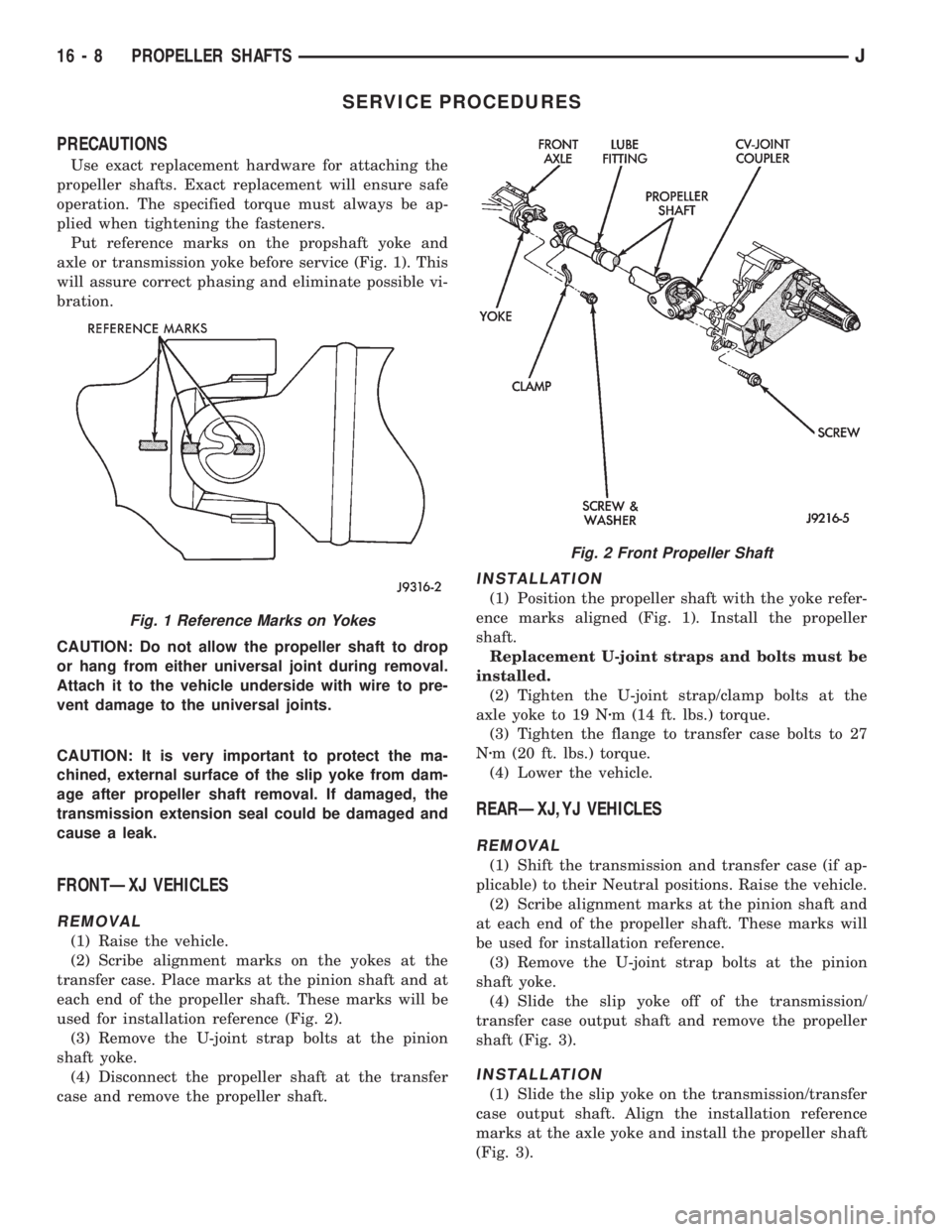
Put reference marks on the propshaft yoke and
axle or transmission yoke before service (Fig. 1). This
will assure correct phasing and eliminate possible vi-
bration.
CAUTION: Do not allow the propeller shaft to drop
or hang from either universal joint during removal.
Attach it to the vehicle underside with wire to pre-
vent damage to the universal joints.
CAUTION: It is very important to protect the ma-
chined, external surface of the slip yoke from dam-
age after propeller shaft removal. If damaged, the
transmission extension seal could be damaged and
cause a leak.
FRONTÐXJ VEHICLES
REMOVAL
(1) Raise the vehicle.
(2) Scribe alignment marks on the yokes at the
transfer case. Place marks at the pinion shaft and at
each end of the propeller shaft. These marks will be
used for installation reference (Fig. 2).
(3) Remove the U-joint strap bolts at the pinion
shaft yoke.
(4) Disconnect the propeller shaft at the transfer
case and remove the propeller shaft.
INSTALLATION
(1) Position the propeller shaft with the yoke refer-
ence marks aligned (Fig. 1). Install the propeller
shaft.
Replacement U-joint straps and bolts must be
installed.
(2) Tighten the U-joint strap/clamp bolts at the
axle yoke to 19 Nzm (14 ft. lbs.) torque.
(3) Tighten the flange to transfer case bolts to 27
Nzm (20 ft. lbs.) torque.
(4) Lower the vehicle.
REARÐXJ,YJ VEHICLES
REMOVAL
(1) Shift the transmission and transfer case (if ap-
plicable) to their Neutral positions. Raise the vehicle.
(2) Scribe alignment marks at the pinion shaft and
at each end of the propeller shaft. These marks will
be used for installation reference.
(3) Remove the U-joint strap bolts at the pinion
shaft yoke.
(4) Slide the slip yoke off of the transmission/
transfer case output shaft and remove the propeller
shaft (Fig. 3).
INSTALLATION
(1) Slide the slip yoke on the transmission/transfer
case output shaft. Align the installation reference
marks at the axle yoke and install the propeller shaft
(Fig. 3).
Fig. 1 Reference Marks on Yokes
Fig. 2 Front Propeller Shaft
16 - 8 PROPELLER SHAFTSJ