1995 JEEP YJ U Joint
[x] Cancel search: U JointPage 540 of 2158
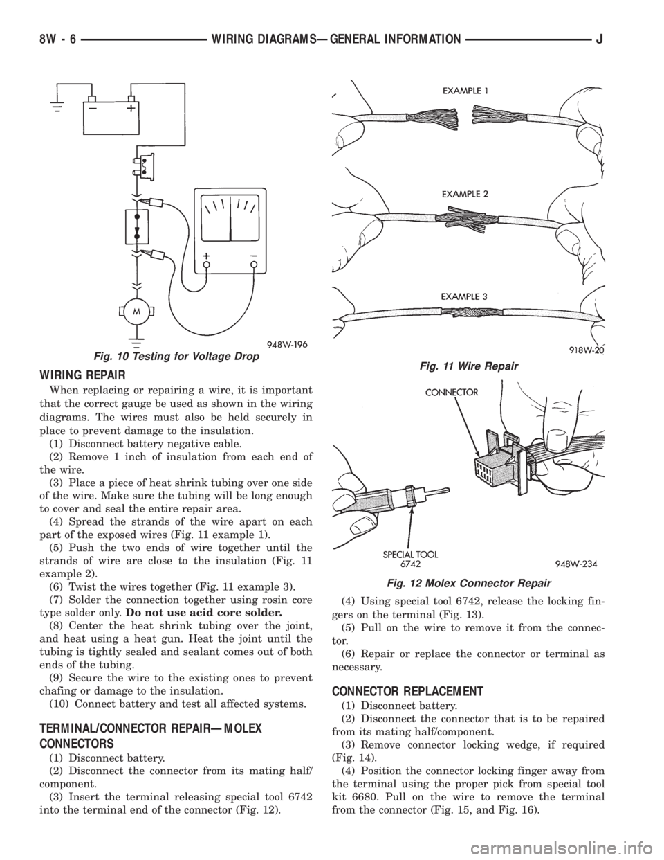
WIRING REPAIR
When replacing or repairing a wire, it is important
that the correct gauge be used as shown in the wiring
diagrams. The wires must also be held securely in
place to prevent damage to the insulation.
(1) Disconnect battery negative cable.
(2) Remove 1 inch of insulation from each end of
the wire.
(3) Place a piece of heat shrink tubing over one side
of the wire. Make sure the tubing will be long enough
to cover and seal the entire repair area.
(4) Spread the strands of the wire apart on each
part of the exposed wires (Fig. 11 example 1).
(5) Push the two ends of wire together until the
strands of wire are close to the insulation (Fig. 11
example 2).
(6) Twist the wires together (Fig. 11 example 3).
(7) Solder the connection together using rosin core
type solder only.Do not use acid core solder.
(8) Center the heat shrink tubing over the joint,
and heat using a heat gun. Heat the joint until the
tubing is tightly sealed and sealant comes out of both
ends of the tubing.
(9) Secure the wire to the existing ones to prevent
chafing or damage to the insulation.
(10) Connect battery and test all affected systems.
TERMINAL/CONNECTOR REPAIRÐMOLEX
CONNECTORS
(1) Disconnect battery.
(2) Disconnect the connector from its mating half/
component.
(3) Insert the terminal releasing special tool 6742
into the terminal end of the connector (Fig. 12).(4) Using special tool 6742, release the locking fin-
gers on the terminal (Fig. 13).
(5) Pull on the wire to remove it from the connec-
tor.
(6) Repair or replace the connector or terminal as
necessary.
CONNECTOR REPLACEMENT
(1) Disconnect battery.
(2) Disconnect the connector that is to be repaired
from its mating half/component.
(3) Remove connector locking wedge, if required
(Fig. 14).
(4) Position the connector locking finger away from
the terminal using the proper pick from special tool
kit 6680. Pull on the wire to remove the terminal
from the connector (Fig. 15, and Fig. 16).
Fig. 10 Testing for Voltage DropFig. 11 Wire Repair
Fig. 12 Molex Connector Repair
8W - 6 WIRING DIAGRAMSÐGENERAL INFORMATIONJ
Page 541 of 2158

(5) Reset the terminal locking tang, if it has one.
(6) Insert the removed wire in the same cavity on
the repair connector.
(7) Repeat steps four through six for each wire in
the connector, being sure that all wires are inserted
into the proper cavities. For additional connector pin-
out identification, refer to the wiring diagrams.
(8) Insert the connector locking wedge into the re-
paired connector, if required.
(9) Connect connector to its mating half/component.
(10) Connect battery and test all affected systems.
CONNECTOR AND TERMINAL REPLACEMENT
(1) Disconnect battery.
(2) Disconnect the connector (that is to be repaired)
from its mating half/component.
(3) Cut off the existing wire connector directly be-
hind the insulator. Remove six inches of tape from the
harness.
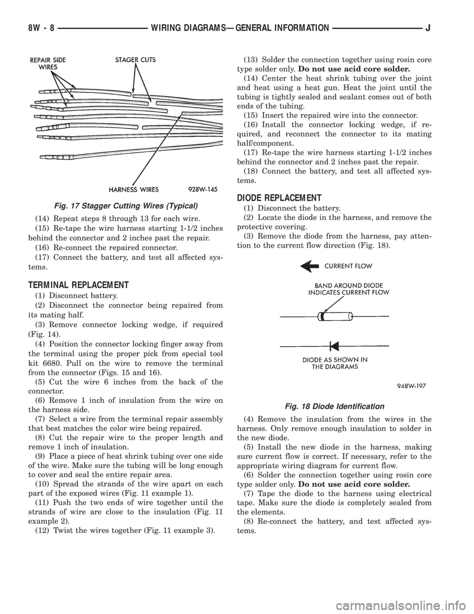
(4) Stagger cut all wires on the harness side at 1/2
inch intervals (Fig. 17).(5) Remove 1 inch of insulation from each wire on
the harness side.
(6) Stagger cut the matching wires on the repair
connector assembly in the opposite order as was done
on the harness side of the repair. Allow extra length
for soldered connections. Check that the overall
length is the same as the original (Fig. 17).
(7) Remove 1 inch of insulation from each wire.
(8) Place a piece of heat shrink tubing over one side
of the wire. Be sure the tubing will be long enough to
cover and seal the entire repair area.
(9) Spread the strands of the wire apart on each
part of the exposed wires (Fig. 11 example 1).
(10) Push the two ends of wire together until the
strands of wire are close to the insulation (Fig. 11
example 2).
(11) Twist the wires together (Fig. 11 example 3).
(12) Solder the connection together using rosin core
type solder only.Do not use acid core solder.
(13) Center the heat shrink tubing over the joint
and heat using a heat gun. Heat the joint until the
tubing is tightly sealed and sealant comes out of both
ends of the tubing.
Fig. 13 Using Special Tool 6742
Fig. 14 Connector Locking Wedge Tab (Typical)
Fig. 15 Terminal Removal
Fig. 16 Terminal Removal Using Special Tool
JWIRING DIAGRAMSÐGENERAL INFORMATION 8W - 7
Page 542 of 2158
(14) Repeat steps 8 through 13 for each wire.
(15) Re-tape the wire harness starting 1-1/2 inches
behind the connector and 2 inches past the repair.
(16) Re-connect the repaired connector.
(17) Connect the battery, and test all affected sys-
tems.
TERMINAL REPLACEMENT
(1) Disconnect battery.
(2) Disconnect the connector being repaired from
its mating half.
(3) Remove connector locking wedge, if required
(Fig. 14).
(4) Position the connector locking finger away from
the terminal using the proper pick from special tool
kit 6680. Pull on the wire to remove the terminal
from the connector (Figs. 15 and 16).
(5) Cut the wire 6 inches from the back of the
connector.
(6) Remove 1 inch of insulation from the wire on
the harness side.
(7) Select a wire from the terminal repair assembly
that best matches the color wire being repaired.
(8) Cut the repair wire to the proper length and
remove 1 inch of insulation.
(9) Place a piece of heat shrink tubing over one side
of the wire. Make sure the tubing will be long enough
to cover and seal the entire repair area.
(10) Spread the strands of the wire apart on each
part of the exposed wires (Fig. 11 example 1).
(11) Push the two ends of wire together until the
strands of wire are close to the insulation (Fig. 11
example 2).
(12) Twist the wires together (Fig. 11 example 3).(13) Solder the connection together using rosin core
type solder only.Do not use acid core solder.
(14) Center the heat shrink tubing over the joint
and heat using a heat gun. Heat the joint until the
tubing is tightly sealed and sealant comes out of both
ends of the tubing.
(15) Insert the repaired wire into the connector.
(16) Install the connector locking wedge, if re-
quired, and reconnect the connector to its mating
half/component.
(17) Re-tape the wire harness starting 1-1/2 inches
behind the connector and 2 inches past the repair.
(18) Connect the battery, and test all affected sys-
tems.
DIODE REPLACEMENT
(1) Disconnect the battery.
(2) Locate the diode in the harness, and remove the
protective covering.
(3) Remove the diode from the harness, pay atten-
tion to the current flow direction (Fig. 18).
(4) Remove the insulation from the wires in the
harness. Only remove enough insulation to solder in
the new diode.
(5) Install the new diode in the harness, making
sure current flow is correct. If necessary, refer to the
appropriate wiring diagram for current flow.
(6) Solder the connection together using rosin core
type solder only.Do not use acid core solder.
(7) Tape the diode to the harness using electrical
tape. Make sure the diode is completely sealed from
the elements.
(8) Re-connect the battery, and test affected sys-
tems.Fig. 17 Stagger Cutting Wires (Typical)
Fig. 18 Diode Identification
8W - 8 WIRING DIAGRAMSÐGENERAL INFORMATIONJ
Page 1280 of 2158
ENGINES
CONTENTS
page page
LUBRICATION SYSTEM................... 37
LUBRICATION SYSTEM................... 79
2.5L ENGINE SERVICE PROCEDURES....... 134.0L ENGINE SERVICE PROCEDURES....... 55
ENGINE DIAGNOSIS...................... 5
STANDARD SERVICE PROCEDURES......... 1
STANDARD SERVICE PROCEDURES
INDEX
page page
Engine Performance........................ 2
Form-In-Place Gaskets...................... 1
Honing Cylinder Bores...................... 2
Hydrostatic Lock........................... 4Measuring with Plastigage.................... 3
Repair Damaged or Worn Threads............. 4
Service Engine Assembly (Short Block).......... 4
FORM-IN-PLACE GASKETS
There are several places where form-in-place gas-
kets are used on the engine.DO NOT use form-in-
place gasket material unless specified.Care
must be taken when applying form-in-place gaskets.
Bead size, continuity and location are of great impor-
tance. Too thin a bead can result in leakage while too
much can result in spill-over. A continuous bead of
the proper width is essential to obtain a leak-free
joint.
Two types of form-in-place gasket materials are
used in the engine area (Mopar Silicone Rubber Ad-
hesive Sealant and Mopar Gasket Maker). Each have
different properties and cannot be used interchange-
ably.
MOPAR SILICONE RUBBER ADHESIVE
SEALANT
Mopar Silicone Rubber Adhesive Sealant, normally
black in color, is available in 3 ounce tubes. Moisture
in the air causes the sealant material to cure. This
material is normally used on flexible metal flanges.
It has a shelf life of a year and will not properly cure
if over aged. Always inspect the package for the ex-
piration date before use.
MOPAR GASKET MAKER
Mopar Gasket Maker, normally red in color, is
available in 6 cc tubes. This anaerobic type gasket
material cures in the absence of air when squeezedbetween smooth machined metallic surfaces. It will
not cure if left in the uncovered tube. DO NOT use
on flexible metal flanges.
SURFACE PREPARATION
Parts assembled with form-in-place gaskets may be
disassembled without unusual effort. In some in-
stances, it may be necessary to lightly tap the part
with a mallet or other suitable tool to break the seal
between the mating surfaces. A flat gasket scraper
may also be lightly tapped into the joint but care
must be taken not to damage the mating surfaces.
Scrape or wire brush all gasket surfaces to remove
all loose material. Inspect stamped parts to ensure
gasket rails are flat. Flatten rails with a hammer on
a flat plate, if required. Gasket surfaces must be free
of oil and dirt. Make sure the old gasket material is
removed from blind attaching holes.
GASKET APPLICATION
Assembling parts using a form-in-place gasket re-
quires care.
Mopar Silicone Rubber Adhesive Sealant should be
applied in a continuous bead approximately 3 mm
(0.12 inch) in diameter. All mounting holes must be
circled. For corner sealing,a3or6mm(1/8 or 1/4
inch) drop is placed in the center of the gasket con-
tact area. Uncured sealant may be removed with a
shop towel. Components should be torqued in place
while the sealant is still wet to the touch (within 10
JENGINES 9 - 1
Page 1314 of 2158
bearing (smallest). This permits easier removal and
installation of the camshaft. The camshaft bearings
are pressure lubricated.
It is not advisable to attempt to replace cam-
shaft bearings unless special removal and in-
stallation tools are available.
Camshaft end play is maintained by the load
placed on the camshaft by the oil pump and distrib-
utor drive gear. The helical cut of the gear holds the
camshaft sprocket thrust face against the cylinder
block face.
INSTALLATION
(1) Clean the camshaft pin hole.
(2) Compress the center of the replacement spring
pin with vise grips.
(3) Carefully drive the pin into the camshaft pin
hole until it is seated.
(4) Install the camshaft sprocket, crankshaft
sprocket and timing chain with the timing marks
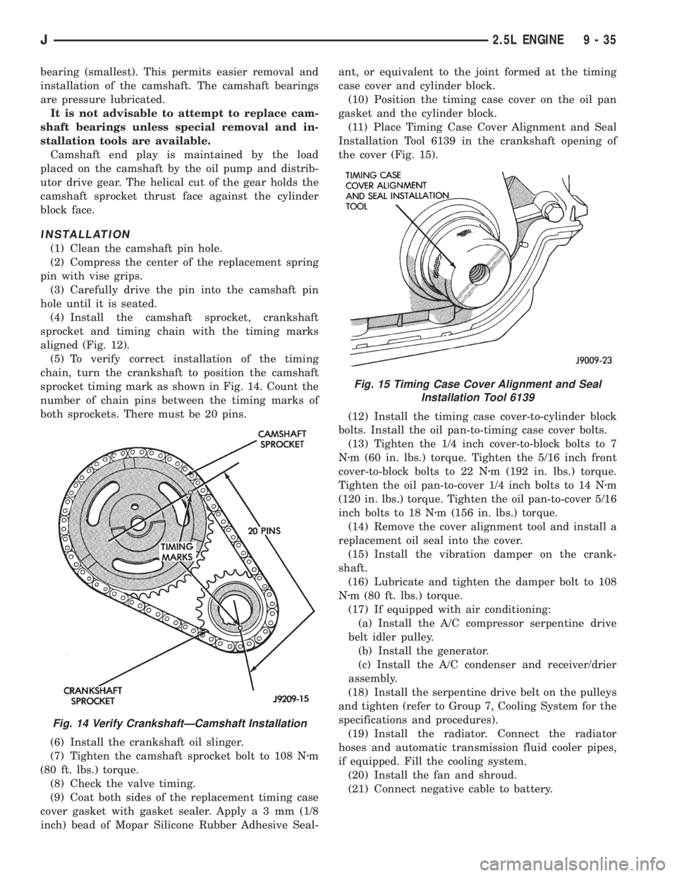
aligned (Fig. 12).
(5) To verify correct installation of the timing
chain, turn the crankshaft to position the camshaft
sprocket timing mark as shown in Fig. 14. Count the
number of chain pins between the timing marks of
both sprockets. There must be 20 pins.
(6) Install the crankshaft oil slinger.
(7) Tighten the camshaft sprocket bolt to 108 Nzm
(80 ft. lbs.) torque.
(8) Check the valve timing.
(9) Coat both sides of the replacement timing case
cover gasket with gasket sealer. Applya3mm(1/8
inch) bead of Mopar Silicone Rubber Adhesive Seal-ant, or equivalent to the joint formed at the timing
case cover and cylinder block.
(10) Position the timing case cover on the oil pan
gasket and the cylinder block.
(11) Place Timing Case Cover Alignment and Seal
Installation Tool 6139 in the crankshaft opening of
the cover (Fig. 15).
(12) Install the timing case cover-to-cylinder block
bolts. Install the oil pan-to-timing case cover bolts.
(13) Tighten the 1/4 inch cover-to-block bolts to 7
Nzm (60 in. lbs.) torque. Tighten the 5/16 inch front
cover-to-block bolts to 22 Nzm (192 in. lbs.) torque.
Tighten the oil pan-to-cover 1/4 inch bolts to 14 Nzm
(120 in. lbs.) torque. Tighten the oil pan-to-cover 5/16
inch bolts to 18 Nzm (156 in. lbs.) torque.
(14) Remove the cover alignment tool and install a
replacement oil seal into the cover.
(15) Install the vibration damper on the crank-
shaft.
(16) Lubricate and tighten the damper bolt to 108
Nzm (80 ft. lbs.) torque.
(17) If equipped with air conditioning:
(a) Install the A/C compressor serpentine drive
belt idler pulley.
(b) Install the generator.
(c) Install the A/C condenser and receiver/drier
assembly.
(18) Install the serpentine drive belt on the pulleys
and tighten (refer to Group 7, Cooling System for the
specifications and procedures).
(19) Install the radiator. Connect the radiator
hoses and automatic transmission fluid cooler pipes,
if equipped. Fill the cooling system.
(20) Install the fan and shroud.
(21) Connect negative cable to battery.
Fig. 14 Verify CrankshaftÐCamshaft Installation
Fig. 15 Timing Case Cover Alignment and Seal
Installation Tool 6139
J2.5L ENGINE 9 - 35
Page 1355 of 2158
(3) Remove the fan and shroud.
(4) Disconnect the radiator overflow tube, radiator
hoses, automatic transmission fluid cooler pipes (if
equipped).
(5) Remove the radiator.
(6) If equipped with air conditioning:
CAUTION: DO NOT loosen or disconnect any air
conditioner system fittings. Move the condenser
and receiver/drier aside as a complete assembly.
(a) Remove the A/C compressor serpentine drive
belt idler pulley.
(b) Disconnect and remove the generator.
(c) Remove the A/C condenser attaching bolts
and move the condenser and receiver/drier assem-
bly up and out of the way.
(7) Remove the serpentine drive belt.
(8) Remove the crankshaft vibration damper.
(9) Remove the timing case cover. Clean the gasket
material from the cover.
(10) Remove the thrust pin and tension spring
from the preload bolt head.
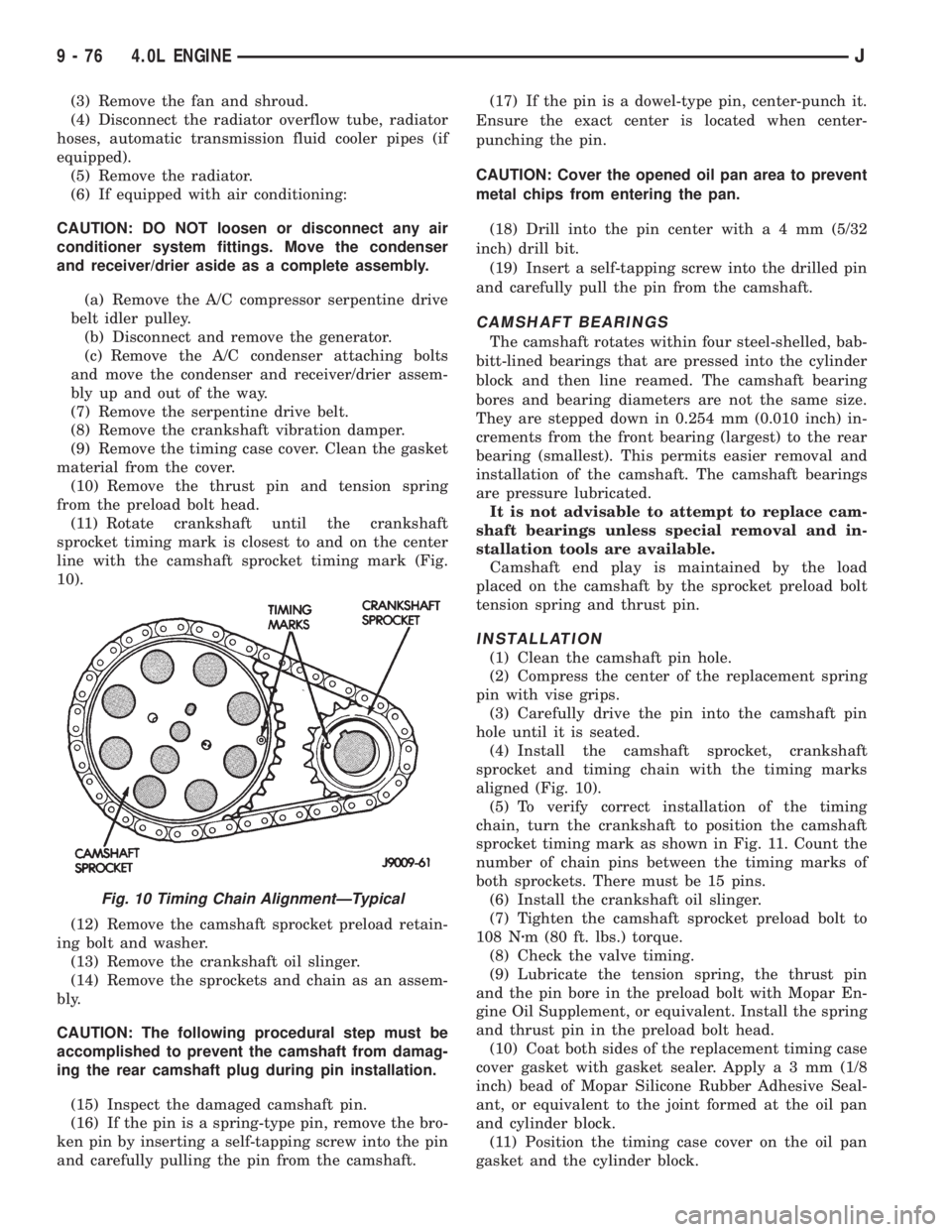
(11) Rotate crankshaft until the crankshaft
sprocket timing mark is closest to and on the center
line with the camshaft sprocket timing mark (Fig.
10).
(12) Remove the camshaft sprocket preload retain-
ing bolt and washer.
(13) Remove the crankshaft oil slinger.
(14) Remove the sprockets and chain as an assem-
bly.
CAUTION: The following procedural step must be
accomplished to prevent the camshaft from damag-
ing the rear camshaft plug during pin installation.
(15) Inspect the damaged camshaft pin.
(16) If the pin is a spring-type pin, remove the bro-
ken pin by inserting a self-tapping screw into the pin
and carefully pulling the pin from the camshaft.(17) If the pin is a dowel-type pin, center-punch it.
Ensure the exact center is located when center-
punching the pin.
CAUTION: Cover the opened oil pan area to prevent
metal chips from entering the pan.
(18) Drill into the pin center witha4mm(5/32
inch) drill bit.
(19) Insert a self-tapping screw into the drilled pin
and carefully pull the pin from the camshaft.
CAMSHAFT BEARINGS
The camshaft rotates within four steel-shelled, bab-
bitt-lined bearings that are pressed into the cylinder
block and then line reamed. The camshaft bearing
bores and bearing diameters are not the same size.
They are stepped down in 0.254 mm (0.010 inch) in-
crements from the front bearing (largest) to the rear
bearing (smallest). This permits easier removal and
installation of the camshaft. The camshaft bearings
are pressure lubricated.
It is not advisable to attempt to replace cam-
shaft bearings unless special removal and in-
stallation tools are available.
Camshaft end play is maintained by the load
placed on the camshaft by the sprocket preload bolt
tension spring and thrust pin.
INSTALLATION
(1) Clean the camshaft pin hole.
(2) Compress the center of the replacement spring
pin with vise grips.
(3) Carefully drive the pin into the camshaft pin
hole until it is seated.
(4) Install the camshaft sprocket, crankshaft
sprocket and timing chain with the timing marks
aligned (Fig. 10).
(5) To verify correct installation of the timing
chain, turn the crankshaft to position the camshaft
sprocket timing mark as shown in Fig. 11. Count the
number of chain pins between the timing marks of
both sprockets. There must be 15 pins.
(6) Install the crankshaft oil slinger.
(7) Tighten the camshaft sprocket preload bolt to
108 Nzm (80 ft. lbs.) torque.
(8) Check the valve timing.
(9) Lubricate the tension spring, the thrust pin
and the pin bore in the preload bolt with Mopar En-
gine Oil Supplement, or equivalent. Install the spring
and thrust pin in the preload bolt head.
(10) Coat both sides of the replacement timing case
cover gasket with gasket sealer. Applya3mm(1/8
inch) bead of Mopar Silicone Rubber Adhesive Seal-
ant, or equivalent to the joint formed at the oil pan
and cylinder block.
(11) Position the timing case cover on the oil pan
gasket and the cylinder block.
Fig. 10 Timing Chain AlignmentÐTypical
9 - 76 4.0L ENGINEJ
Page 1376 of 2158
EXHAUST SYSTEM AND INTAKE MANIFOLD
CONTENTS
page page
EXHAUST SYSTEM....................... 1
EXHAUST SYSTEM DIAGNOSIS............. 2SERVICE PROCEDURES................... 3
TORQUE SPECIFICATIONS................ 10
EXHAUST SYSTEM
GENERAL INFORMATION
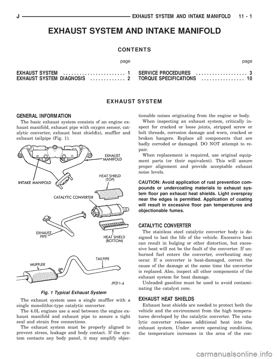
The basic exhaust system consists of an engine ex-
haust manifold, exhaust pipe with oxygen sensor, cat-
alytic converter, exhaust heat shield(s), muffler and
exhaust tailpipe (Fig. 1).
The exhaust system uses a single muffler with a
single monolithic-type catalytic converter.
The 4.0L engines use a seal between the engine ex-
haust manifold and exhaust pipe to assure a tight
seal and strain free connections.
The exhaust system must be properly aligned to
prevent stress, leakage and body contact. If the sys-
tem contacts any body panel, it may amplify objec-tionable noises originating from the engine or body.
When inspecting an exhaust system, critically in-
spect for cracked or loose joints, stripped screw or
bolt threads, corrosion damage and worn, cracked or
broken hangers. Replace all components that are
badly corroded or damaged. DO NOT attempt to re-
pair.
When replacement is required, use original equip-
ment parts (or their equivalent). This will assure
proper alignment and provide acceptable exhaust
noise levels.
CAUTION: Avoid application of rust prevention com-
pounds or undercoating materials to exhaust sys-
tem floor pan exhaust heat shields. Light overspray
near the edges is permitted. Application of coating
will result in excessive floor pan temperatures and
objectionable fumes.
CATALYTIC CONVERTER
The stainless steel catalytic converter body is de-
signed to last the life of the vehicle. Excessive heat
can result in bulging or other distortion, but exces-
sive heat will not be the fault of the converter. If un-
burned fuel enters the converter, overheating may
occur. If a converter is heat-damaged, correct the
cause of the damage at the same time the converter
is replaced. Also, inspect all other components of the
exhaust system for heat damage.
Unleaded gasoline must be used to avoid contami-
nating the catalyst core.
EXHAUST HEAT SHIELDS
Exhaust heat shields are needed to protect both the
vehicle and the environment from the high tempera-
tures developed by the catalytic converter. The cata-
lytic converter releases additional heat into the
exhaust system. Under severe operating conditions,
the temperature increases in the area of the con-
Fig. 1 Typical Exhaust System
JEXHAUST SYSTEM AND INTAKE MANIFOLD 11 - 1
Page 1395 of 2158
FRAME
INDEX
page page
Frame Dimensions........................ 13
Frame Repairs........................... 13
Frame Straightening....................... 13
Fuel Tank Skid Plate....................... 15
General Information....................... 10Generator Splash Shield.................... 13
Safety Precautions and Warnings............. 10
Tow Hooks.............................. 13
Transfer Case Skid Plate.................... 15
SAFETY PRECAUTIONS AND WARNINGS
WARNING: USE EYE PROTECTION WHEN GRIND-
ING OR WELDING METAL, SERIOUS EYE INJURY
CAN RESULT.
BEFORE PROCEEDING WITH FRAME REPAIR IN-
VOLVING GRINDING OR WELDING, VERIFY THAT
VEHICLE FUEL SYSTEM IS NOT LEAKING OR IN
CONTACT WITH REPAIR AREA, PERSONAL INJURY
CAN RESULT.
DO NOT ALLOW OPEN FLAME TO CONTACT
PLASTIC BODY PANELS. FIRE OR EXPLOSION CAN
RESULT.
WHEN WELDED FRAME COMPONENTS ARE RE-
PLACED, 100% PENETRATION WELD MUST BE
ACHIEVED DURING INSTALLATION. IF NOT, DAN-
GEROUS OPERATING CONDITIONS CAN RESULT.
STAND CLEAR OF CABLES OR CHAINS ON
PULLING EQUIPMENT DURING FRAME STRAIGHT-
ENING OPERATIONS, PERSONAL INJURY CAN RE-
SULT.
DO NOT VENTURE UNDER A HOISTED VEHICLE
THAT IS NOT SUPPORTED ON SAFETY STANDS,
PERSONAL INJURY CAN RESULT.
CAUTION: Do not reuse damaged fasteners, quality
of repair would be suspect.
Do not drill holes in top or bottom frame rail
flanges, frame rail failure can result.
Do Not use softer than Grade 3 bolts to replace
production fasteners, loosening or failure can re-
sult.When using heat to straighten frame components
do not exceed 566ÉC (1050ÉF), metal fatigue can re-
sult.
Welding the joints around riveted cross members
and frame side rails can weaken frame
GENERAL INFORMATION
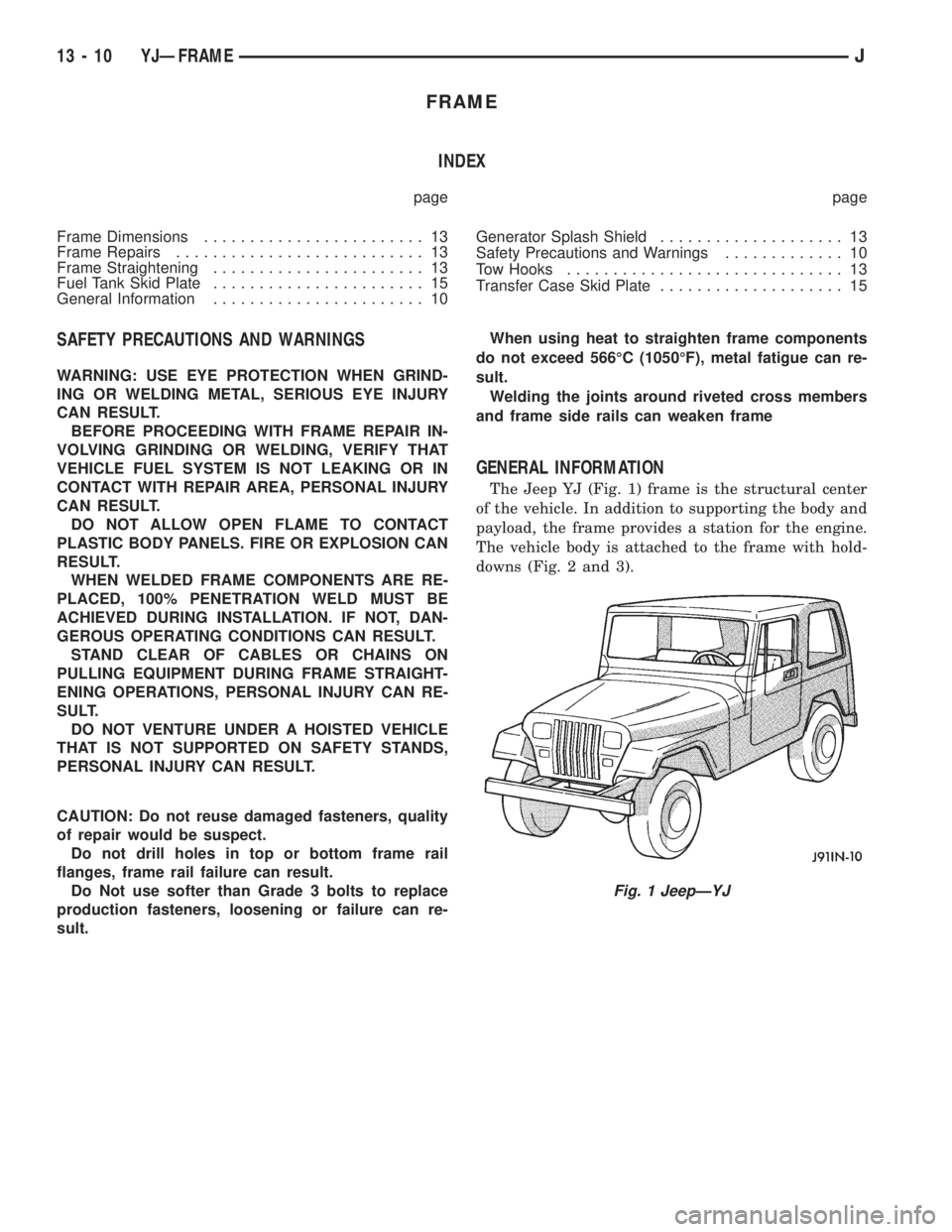
The Jeep YJ (Fig. 1) frame is the structural center
of the vehicle. In addition to supporting the body and
payload, the frame provides a station for the engine.
The vehicle body is attached to the frame with hold-
downs (Fig. 2 and 3).
Fig. 1 JeepÐYJ
13 - 10 YJÐFRAMEJ