1995 JEEP YJ U Joint
[x] Cancel search: U JointPage 1478 of 2158
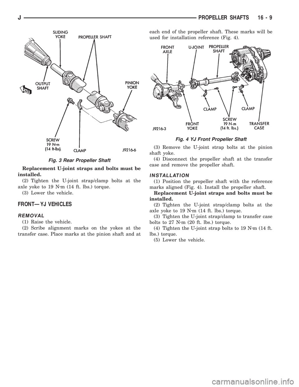
Replacement U-joint straps and bolts must be
installed.
(2) Tighten the U-joint strap/clamp bolts at the
axle yoke to 19 Nzm (14 ft. lbs.) torque.
(3) Lower the vehicle.
FRONTÐYJ VEHICLES
REMOVAL
(1) Raise the vehicle.
(2) Scribe alignment marks on the yokes at the
transfer case. Place marks at the pinion shaft and ateach end of the propeller shaft. These marks will be
used for installation reference (Fig. 4).
(3) Remove the U-joint strap bolts at the pinion
shaft yoke.
(4) Disconnect the propeller shaft at the transfer
case and remove the propeller shaft.
INSTALLATION
(1) Position the propeller shaft with the reference
marks aligned (Fig. 4). Install the propeller shaft.
Replacement U-joint straps and bolts must be
installed.
(2) Tighten the U-joint strap/clamp bolts at the
axle yoke to 19 Nzm (14 ft. lbs.) torque.
(3) Tighten the U-joint strap/clamp to transfer case
bolts to 27 Nzm (20 ft. lbs.) torque.
(4) Tighten the U-joint strap bolts to 19 Nzm (14 ft.
lbs.) torque.
(5) Lower the vehicle.
Fig. 3 Rear Propeller Shaft
Fig. 4 YJ Front Propeller Shaft
JPROPELLER SHAFTS 16 - 9
Page 1479 of 2158
UNIVERSAL JOINT REPLACEMENT
PRECAUTIONS
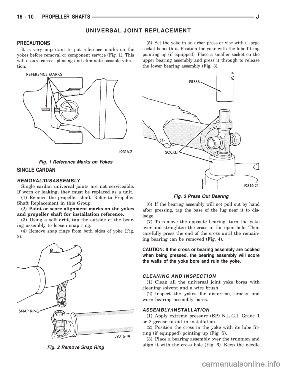
It is very important to put reference marks on the
yokes before removal or component service (Fig. 1). This
will assure correct phasing and eliminate possible vibra-
tion.
SINGLE CARDAN
REMOVAL/DISASSEMBLY
Single cardan universal joints are not serviceable.
If worn or leaking, they must be replaced as a unit.
(1) Remove the propeller shaft. Refer to Propeller
Shaft Replacement in this Group.
(2)Paint or score alignment marks on the yokes
and propeller shaft for installation reference.
(3) Using a soft drift, tap the outside of the bear-
ing assembly to loosen snap ring.
(4) Remove snap rings from both sides of yoke (Fig.
2).(5) Set the yoke in an arbor press or vise with a large
socket beneath it. Position the yoke with the lube fitting
pointing up (if equipped). Place a smaller socket on the
upper bearing assembly and press it through to release
the lower bearing assembly (Fig. 3).
(6) If the bearing assembly will not pull out by hand
after pressing, tap the base of the lug near it to dis-
lodge.
(7) To remove the opposite bearing, turn the yoke
over and straighten the cross in the open hole. Then
carefully press the end of the cross until the remain-
ing bearing can be removed (Fig. 4).
CAUTION: If the cross or bearing assembly are cocked
when being pressed, the bearing assembly will score
the walls of the yoke bore and ruin the yoke.
CLEANING AND INSPECTION
(1) Clean all the universal joint yoke bores with
cleaning solvent and a wire brush.
(2) Inspect the yokes for distortion, cracks and
worn bearing assembly bores.
ASSEMBLY/INSTALLATION
(1) Apply extreme pressure (EP) N.L.G.I. Grade 1
or 2 grease to aid in installation.
(2) Position the cross in the yoke with its lube fit-
ting (if equipped) pointing up (Fig. 5).
(3) Place a bearing assembly over the trunnion and
align it with the cross hole (Fig. 6). Keep the needle
Fig. 1 Reference Marks on Yokes
Fig. 2 Remove Snap Ring
Fig. 3 Press Out Bearing
16 - 10 PROPELLER SHAFTSJ
Page 1480 of 2158
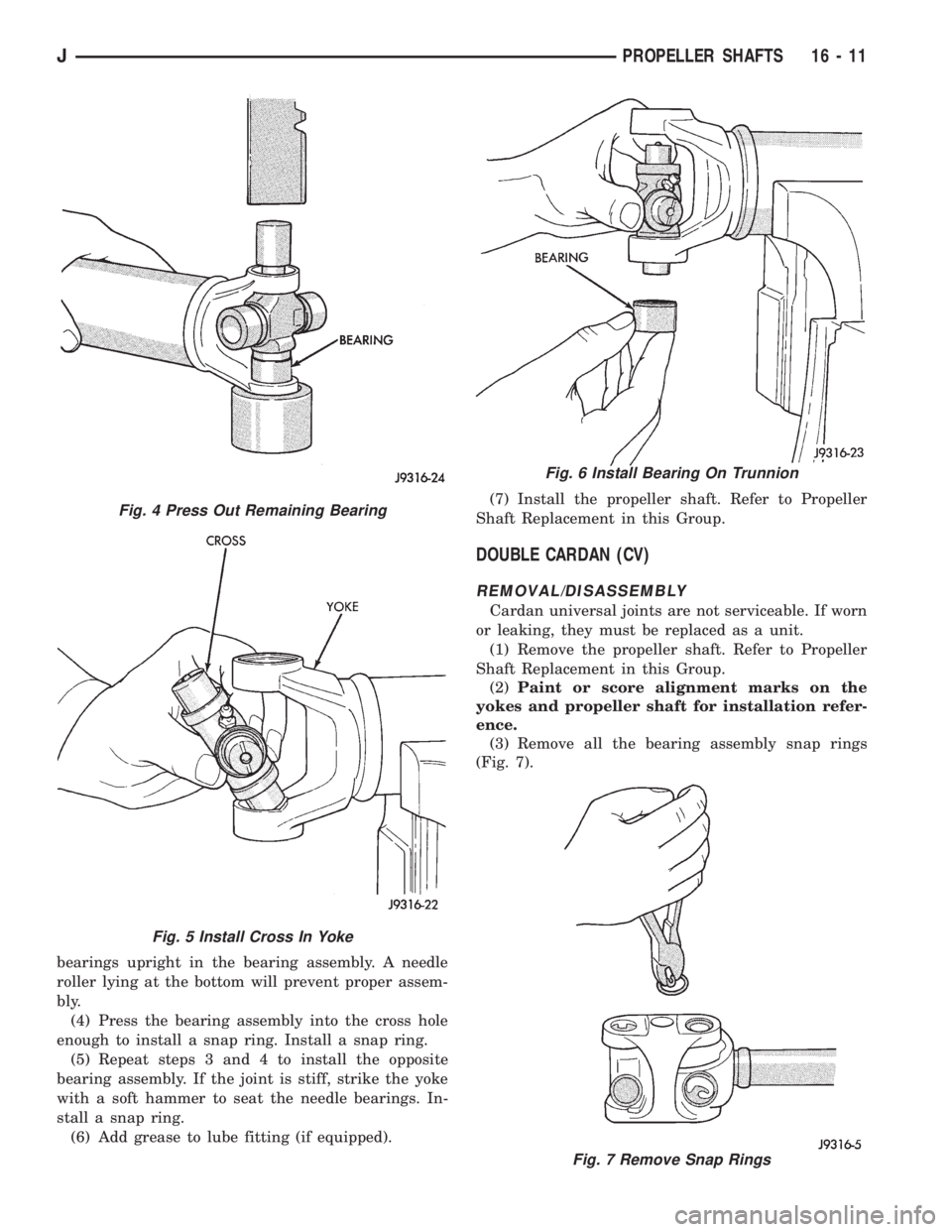
bearings upright in the bearing assembly. A needle
roller lying at the bottom will prevent proper assem-
bly.
(4) Press the bearing assembly into the cross hole
enough to install a snap ring. Install a snap ring.
(5) Repeat steps 3 and 4 to install the opposite
bearing assembly. If the joint is stiff, strike the yoke
with a soft hammer to seat the needle bearings. In-
stall a snap ring.
(6) Add grease to lube fitting (if equipped).(7) Install the propeller shaft. Refer to Propeller
Shaft Replacement in this Group.
DOUBLE CARDAN (CV)
REMOVAL/DISASSEMBLY
Cardan universal joints are not serviceable. If worn
or leaking, they must be replaced as a unit.
(1) Remove the propeller shaft. Refer to Propeller
Shaft Replacement in this Group.
(2)Paint or score alignment marks on the
yokes and propeller shaft for installation refer-
ence.
(3) Remove all the bearing assembly snap rings
(Fig. 7).
Fig. 4 Press Out Remaining Bearing
Fig. 5 Install Cross In Yoke
Fig. 6 Install Bearing On Trunnion
Fig. 7 Remove Snap Rings
JPROPELLER SHAFTS 16 - 11
Page 1481 of 2158
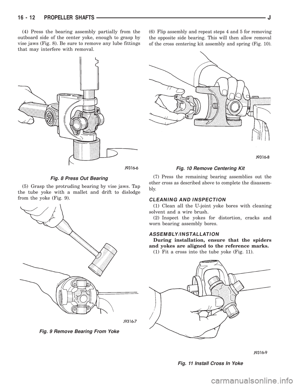
(4) Press the bearing assembly partially from the
outboard side of the center yoke, enough to grasp by
vise jaws (Fig. 8). Be sure to remove any lube fittings
that may interfere with removal.
(5) Grasp the protruding bearing by vise jaws. Tap
the tube yoke with a mallet and drift to dislodge
from the yoke (Fig. 9).(6) Flip assembly and repeat steps 4 and 5 for removing
the opposite side bearing. This will then allow removal
of the cross centering kit assembly and spring (Fig. 10).
(7) Press the remaining bearing assemblies out the
other cross as described above to complete the disassem-
bly.
CLEANING AND INSPECTION
(1) Clean all the U-joint yoke bores with cleaning
solvent and a wire brush.
(2) Inspect the yokes for distortion, cracks and
worn bearing assembly bores.
ASSEMBLY/INSTALLATION
During installation, ensure that the spiders
and yokes are aligned to the reference marks.
(1) Fit a cross into the tube yoke (Fig. 11).
Fig. 8 Press Out Bearing
Fig. 9 Remove Bearing From Yoke
Fig. 10 Remove Centering Kit
Fig. 11 Install Cross In Yoke
16 - 12 PROPELLER SHAFTSJ
Page 1484 of 2158
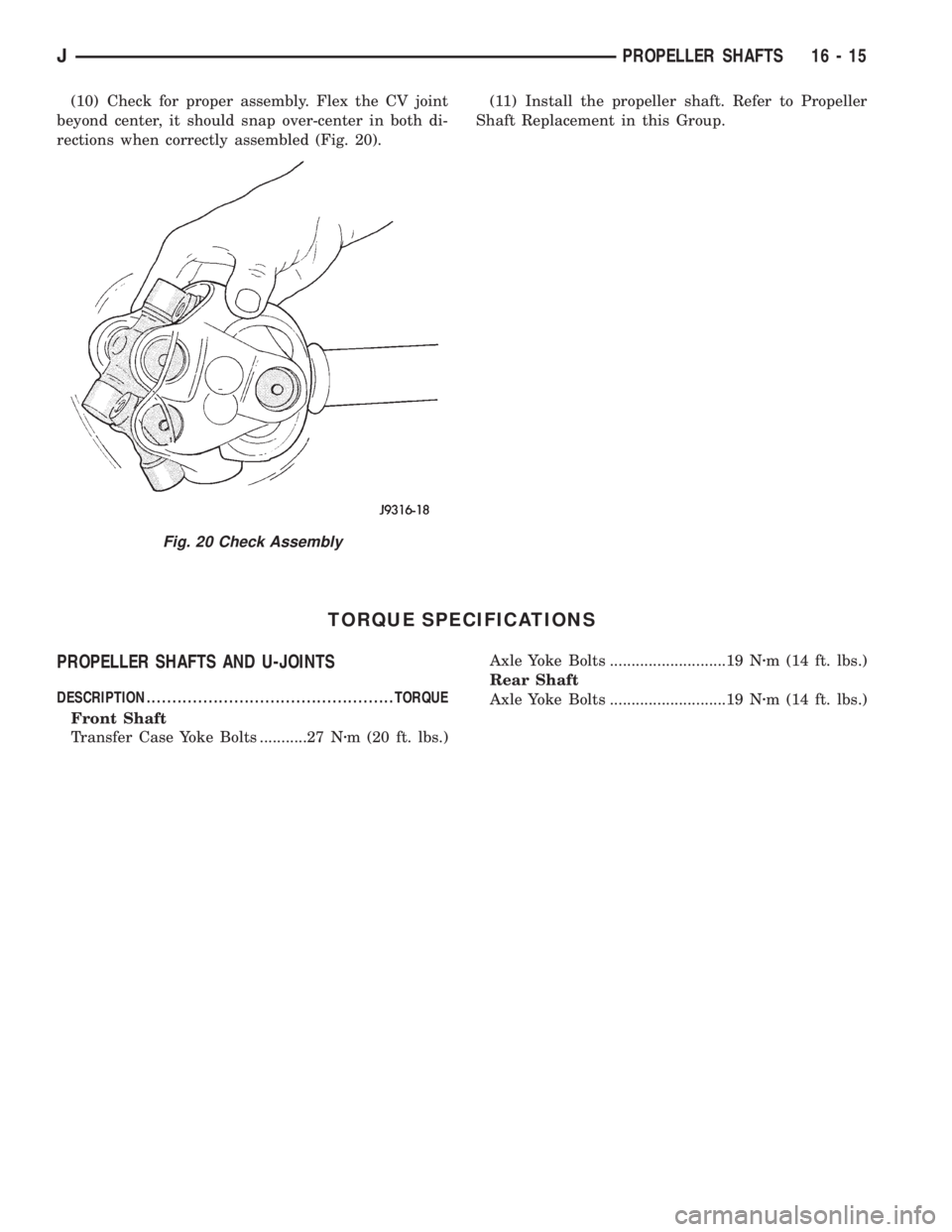
(10) Check for proper assembly. Flex the CV joint
beyond center, it should snap over-center in both di-
rections when correctly assembled (Fig. 20).(11) Install the propeller shaft. Refer to Propeller
Shaft Replacement in this Group.
TORQUE SPECIFICATIONS
PROPELLER SHAFTS AND U-JOINTS
DESCRIPTION ................................................TORQUE
Front Shaft
Transfer Case Yoke Bolts ...........27 Nzm (20 ft. lbs.)Axle Yoke Bolts ...........................19 Nzm (14 ft. lbs.)
Rear Shaft
Axle Yoke Bolts ...........................19 Nzm (14 ft. lbs.)
Fig. 20 Check Assembly
JPROPELLER SHAFTS 16 - 15
Page 1485 of 2158
STEERING
CONTENTS
page page
GENERAL INFORMATION.................. 1
GENERAL INFORMATION................. 48
MANUAL STEERING GEAR................ 37
POWER STEERING PUMP................. 11
POWER STEERING SYSTEM DIAGNOSIS...... 3
RECIRCULATING BALL POWER STEERING
GEAR............................... 21STEERING COLUMN GENERAL SERVICEÐXJ . 47
STEERING COLUMNÐYJ................. 58
STEERING LINKAGEÐXJ................. 16
STEERING LINKAGEÐYJ................. 19
STEERING RHD......................... 74
TORQUE SPECIFICATIONS................ 78
GENERAL INFORMATION
STEERING SYSTEM COMPONENTS
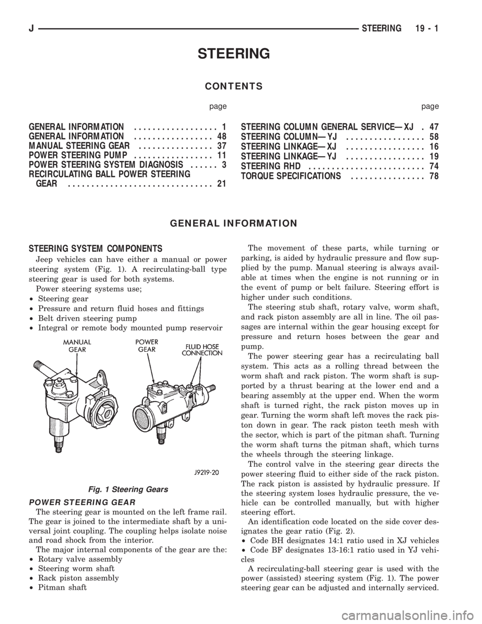
Jeep vehicles can have either a manual or power
steering system (Fig. 1). A recirculating-ball type
steering gear is used for both systems.
Power steering systems use;
²Steering gear
²Pressure and return fluid hoses and fittings
²Belt driven steering pump
²Integral or remote body mounted pump reservoir
POWER STEERING GEAR
The steering gear is mounted on the left frame rail.
The gear is joined to the intermediate shaft by a uni-
versal joint coupling. The coupling helps isolate noise
and road shock from the interior.
The major internal components of the gear are the:
²Rotary valve assembly
²Steering worm shaft
²Rack piston assembly
²Pitman shaftThe movement of these parts, while turning or
parking, is aided by hydraulic pressure and flow sup-
plied by the pump. Manual steering is always avail-
able at times when the engine is not running or in
the event of pump or belt failure. Steering effort is
higher under such conditions.
The steering stub shaft, rotary valve, worm shaft,
and rack piston assembly are all in line. The oil pas-
sages are internal within the gear housing except for
pressure and return hoses between the gear and
pump.
The power steering gear has a recirculating ball
system. This acts as a rolling thread between the
worm shaft and rack piston. The worm shaft is sup-
ported by a thrust bearing at the lower end and a
bearing assembly at the upper end. When the worm
shaft is turned right, the rack piston moves up in
gear. Turning the worm shaft left moves the rack pis-
ton down in gear. The rack piston teeth mesh with
the sector, which is part of the pitman shaft. Turning
the worm shaft turns the pitman shaft, which turns
the wheels through the steering linkage.
The control valve in the steering gear directs the
power steering fluid to either side of the rack piston.
The rack piston is assisted by hydraulic pressure. If
the steering system loses hydraulic pressure, the ve-
hicle can be controlled manually, but with higher
steering effort.
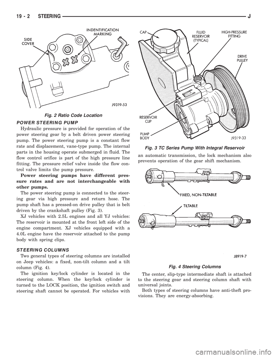
An identification code located on the side cover des-
ignates the gear ratio (Fig. 2).
²Code BH designates 14:1 ratio used in XJ vehicles
²Code BF designates 13-16:1 ratio used in YJ vehi-
cles
A recirculating-ball steering gear is used with the
power (assisted) steering system (Fig. 1). The power
steering gear can be adjusted and internally serviced.
Fig. 1 Steering Gears
JSTEERING 19 - 1
Page 1486 of 2158
POWER STEERING PUMP
Hydraulic pressure is provided for operation of the
power steering gear by a belt driven power steering
pump. The power steering pump is a constant flow
rate and displacement, vane-type pump. The internal
parts in the housing operate submerged in fluid. The
flow control orifice is part of the high pressure line
fitting. The pressure relief valve inside the flow con-
trol valve limits the pump pressure.
Power steering pumps have different pres-
sure rates and are not interchangeable with
other pumps.
The power steering pump is connected to the steer-
ing gear via high pressure and return hose. The
pump shaft has a pressed-on drive pulley that is belt
driven by the crankshaft pulley (Fig. 3).
XJ vehicles with 2.5L engines and all YJ vehicles:
The reservoir is mounted at the front left side of the
engine compartment. XJ vehicles equipped with a
4.0L engine have the reservoir attached to the pump
body with spring clips.
STEERING COLUMNS
Two general types of steering columns are installed
on Jeep vehicles: a fixed, non-tilt column and a tilt
column (Fig. 4).
The ignition key/lock cylinder is located in the
steering column. When the key/lock cylinder is
turned to the LOCK position, the ignition switch and
steering shaft cannot be operated. For vehicles withan automatic transmission, the lock mechanism also
prevents operation of the gear shift mechanism.
The center, slip-type intermediate shaft is attached
to the steering gear and steering column shaft with
universal joints.
Both types of steering columns have anti-theft pro-
visions. They are energy-absorbing.
Fig. 2 Ratio Code Location
Fig. 3 TC Series Pump With Integral Reservoir
Fig. 4 Steering Columns
19 - 2 STEERINGJ
Page 1554 of 2158
replaced, remove them with a hammer and punch.
Discard the bearings and races after removal. They
are not reusable.
(37) Remove the steering shaft from the upper end
of the steering column.
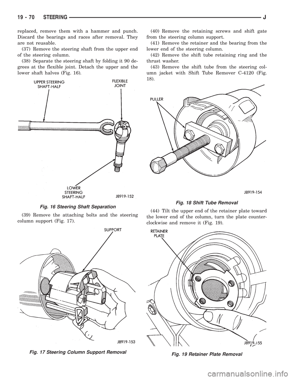
(38) Separate the steering shaft by folding it 90 de-
grees at the flexible joint. Detach the upper and the
lower shaft halves (Fig. 16).
(39) Remove the attaching bolts and the steering
column support (Fig. 17).(40) Remove the retaining screws and shift gate
from the steering column support.
(41) Remove the retainer and the bearing from the
lower end of the steering column.
(42) Remove the shift tube retaining ring and the
thrust washer.
(43) Remove the shift tube from the steering col-
umn jacket with Shift Tube Remover C-4120 (Fig.
18).
(44) Tilt the upper end of the retainer plate toward
the lower end of the column, turn the plate counter-
clockwise and remove it (Fig. 19).
Fig. 16 Steering Shaft Separation
Fig. 17 Steering Column Support Removal
Fig. 18 Shift Tube Removal
Fig. 19 Retainer Plate Removal
19 - 70 STEERINGJ