Page 1872 of 2158

(6) Install vehicle speed sensor and adapter, if re-
moved. Then connect vehicle speed sensor wires, vent
hoses and electrical switch connector.
(7) Align and connect propeller shafts. Tighten
shaft U-joint clamp bolts to 19 Nzm (14 ft. lbs.)
torque.
(8) Fill transfer case with Mopar Dexron II. Cor-
rect fill level is to bottom edge of fill plug hole.
(9) Install rear crossmember. Tighten crossmember
bolts to 41 Nzm (30 ft. lbs.) torque.
(10) Remove transmission jack and transmission
support stand.
(11) Move transfer case range lever to 4L position.
(12) Connect shift rod to transfer case range lever.
(13) Adjust transfer case shift linkage as described
in this section.
(14) Lower vehicle.
TRANSFER CASE DISASSEMBLY AND OVERHAUL
(1) Remove fill and drain plugs.
(2) Remove front yoke. Discard yoke seal washer
and nut.
(3) Place transfer case range lever in 4L position.
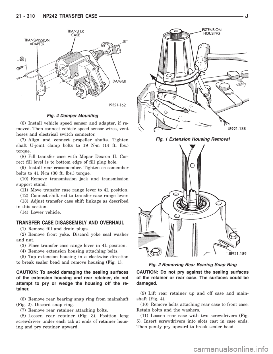
(4) Remove extension housing attaching bolts.
(5) Tap extension housing in a clockwise direction
to break sealer bead and remove housing (Fig. 1).
CAUTION: To avoid damaging the sealing surfaces
of the extension housing and rear retainer, do not
attempt to pry or wedge the housing off the re-
tainer.
(6) Remove rear bearing snap ring from mainshaft
(Fig. 2). Discard snap ring.
(7) Remove rear retainer attaching bolts.
(8) Loosen rear retainer (Fig. 3). Position long
screwdriver under each tab at ends of retainer hous-
ing and pry retainer upward.CAUTION: Do not pry against the sealing surfaces
of the retainer or rear case. The surfaces could be
damaged.
(9) Lift rear retainer up and off case and main-
shaft (Fig. 4).
(10) Remove bolts attaching rear case to front case.
Retain bolts and the washers.
(11) Loosen rear case with two screwdrivers (Fig.
5). Insert screwdrivers into slots cast in case ends.
Then gently pry upward to break sealer bead.
Fig. 4 Damper Mounting
Fig. 1 Extension Housing Removal
Fig. 2 Removing Rear Bearing Snap Ring
21 - 310 NP242 TRANSFER CASEJ
Page 1884 of 2158
(16) Install new input gear snap ring (Fig. 47).
(17) Install new seal in front bearing retainer with
Tool Handle C-4171 and Installer 7884 (Fig. 48).(18) Apply 3 mm (1/8 in.) wide bead of Mopar gasket
maker. silicone adhesive sealer, or Loctite 518 to seal
surface of front bearing retainer.
(19) Install front bearing retainer (Fig. 49).
Tighten retainer bolts to 16 ft. lbs. (21 Nzm) torque.
(20) Install new sector shaft O-ring and bushing
(Fig. 50).
(21) Install shift sector.
Fig. 47 Input Gear Snap Ring Installation
Fig. 48 Front Bearing Retainer Seal Installation
Fig. 49 Installing Front Bearing Retainer
Fig. 50 Sector O-Ring And Bushing Installation
21 - 322 NP242 TRANSFER CASEJ
Page 1886 of 2158
(29) Align and position differential top case on bot-
tom case (Fig. 55). Align using scribe marks made at
disassembly.
(30) Install and tighten differential case bolts to
specified torque.
(31) Install first mainshaft bearing spacer on
mainshaft (Fig. 56).(32) Install bearing rollers on mainshaft (Fig. 56).
Coat bearing rollers with generous quantity of
petroleum jelly to hold them in place.
(33) Install remaining bearing spacer on mainshaft
(Fig. 56). Do not displace any bearings while install-
ing spacer.
(34) Install differential (Fig. 57).Do not displace
mainshaft bearings when installing differential.
(35) Install differential snap ring (Fig. 58).
Fig. 56 Installing Mainshaft Bearing Rollers and
Spacers
Fig. 55 Differential Case Assembly
Fig. 57 Differential Installation
Fig. 58 Installing Differential Snap Ring
21 - 324 NP242 TRANSFER CASEJ
Page 1889 of 2158
(46) Insert lockpin through access hole and into
shift fork (Fig. 66). Then remove easy-out and seat
the pin with pin punch.
(47) Install plug in lockpin access hole.
(48) Install transfer case shift lever and attaching
nut. Tighten nut to 30 Nzm (22 ft. lbs.) torque.
(49) Install detent plunger, detent spring and de-
tent plug in case (Fig. 67).(50) Install front output shaft (Fig. 68).
(51) Install drive chain (Fig. 68). Engage chain
with front output shaft sprocket teeth.
(52) Install drive sprocket (Fig. 68).
(53) Engage drive sprocket teeth with chain. Then
engage sprocket splines with mainshaft splines.
(54) Install drive sprocket snap ring (Fig. 69).
Fig. 66 Installing Low Range Fork Lockpin
Fig. 67 Detent Pin, Spring And Plug Installation
Fig. 68 Drive Chain And Sprocket Installation
Fig. 69 Drive Sprocket Snap Ring Installation
JNP242 TRANSFER CASE 21 - 327
Page 1891 of 2158

(62) Install and tighten front case-to-rear case
bolts to 41 Nzm (30 ft. lbs.) torque.Be sure to in-
stall a washer under each bolt used at case
dowel locations.
(63) Tap rear retainer bearing out of retainer with
hammer and brass drift.
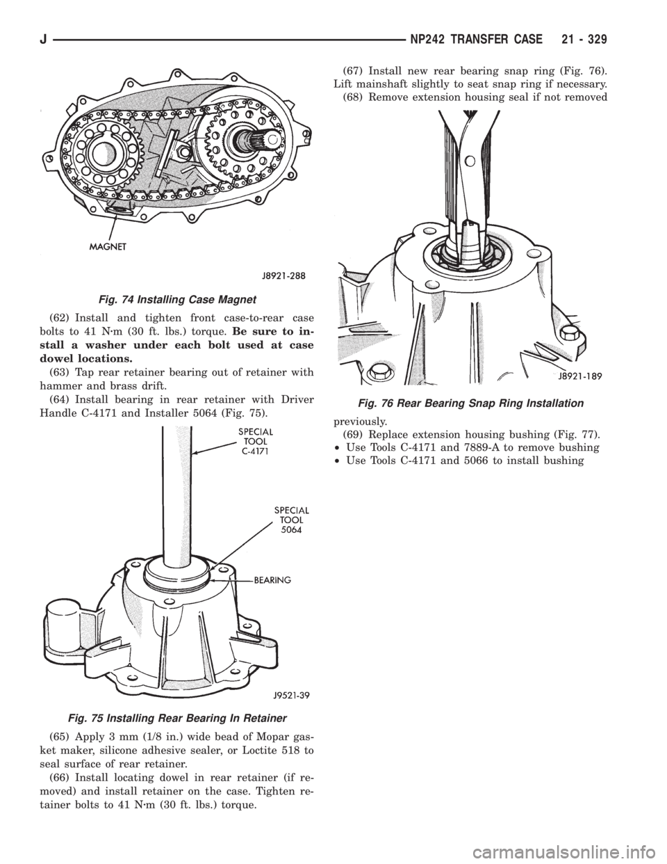
(64) Install bearing in rear retainer with Driver
Handle C-4171 and Installer 5064 (Fig. 75).
(65) Apply 3 mm (1/8 in.) wide bead of Mopar gas-
ket maker, silicone adhesive sealer, or Loctite 518 to
seal surface of rear retainer.
(66) Install locating dowel in rear retainer (if re-
moved) and install retainer on the case. Tighten re-
tainer bolts to 41 Nzm (30 ft. lbs.) torque.(67) Install new rear bearing snap ring (Fig. 76).
Lift mainshaft slightly to seat snap ring if necessary.
(68) Remove extension housing seal if not removed
previously.
(69) Replace extension housing bushing (Fig. 77).
²Use Tools C-4171 and 7889-A to remove bushing
²Use Tools C-4171 and 5066 to install bushing
Fig. 74 Installing Case Magnet
Fig. 75 Installing Rear Bearing In Retainer
Fig. 76 Rear Bearing Snap Ring Installation
JNP242 TRANSFER CASE 21 - 329
Page 1892 of 2158
(70) Install new extension housing oil seal with Spe-
cial Tool 7891 (Fig. 78).
(71) Apply 3 mm (1/8 in.) wide bead of Mopar gas-
ket maker, silicone adhesive sealer, or Loctite 518 to
seal surface of extension housing.
(72) Install extension housing on case. Tighten
housing bolts to 41 Nzm (30 ft. lbs.) torque.(73) Install front yoke. Secure yoke with new seal
washer and nut. Tighten nut to 149 Nzm (110 ft. lbs.)
torque.
(74) Install new gasket on vacuum switch and in-
stall switch in case. Tighten switch to 27 Nzm (20 ft.
lbs.) torque.
(75) Install speedometer components.
(76) Install and tighten drain plug to 47 Nzm (35
ft. lbs.) torque.
(77) After installing transfer case, refill with rec-
ommended lubricant.
(78) Tighten fill plug to 47 Nzm (35 ft. lbs.) torque.
(79) Adjust transfer case shift linkage.
Fig. 77 Extension Housing Bushing Replacement
Fig. 78 Seating Extension Housing Seal
21 - 330 NP242 TRANSFER CASEJ
Page 1895 of 2158
TRANSMISSION/TRANSFER CASE SPECIFICATIONS
TORQUE SPECIFICATIONSÐMANUAL
TRANSMISSION
JTRANSMISSION/TRANSFER CASE SPECIFICATIONS 21 - 333
Page 1898 of 2158
30RH/32RH PRESSURE TEST SPECIFICATIONS
30RH/32RH TORQUE SPECIFICATIONS
21 - 336 TRANSMISSION/TRANSFER CASE SPECIFICATIONSJ