Page 1944 of 2158
(3) Pull downward and remove the grille from ex-
haust port in the door opening panel.
INSTALLATION
(1) Position the slot located in the upper end of re-
placement grille at the exhaust port and insert edge
in the slot.
(2) Push inward and seat the grille in the exhaust
port.
(3) Install the screw to attach the grille to the door
opening panel.
EXTERIOR NAMEPLATESÐXJ
SERVICE INFORMATION
All of nameplates, with the exception of the JEEP
nameplate located on the grille are attached with ad-
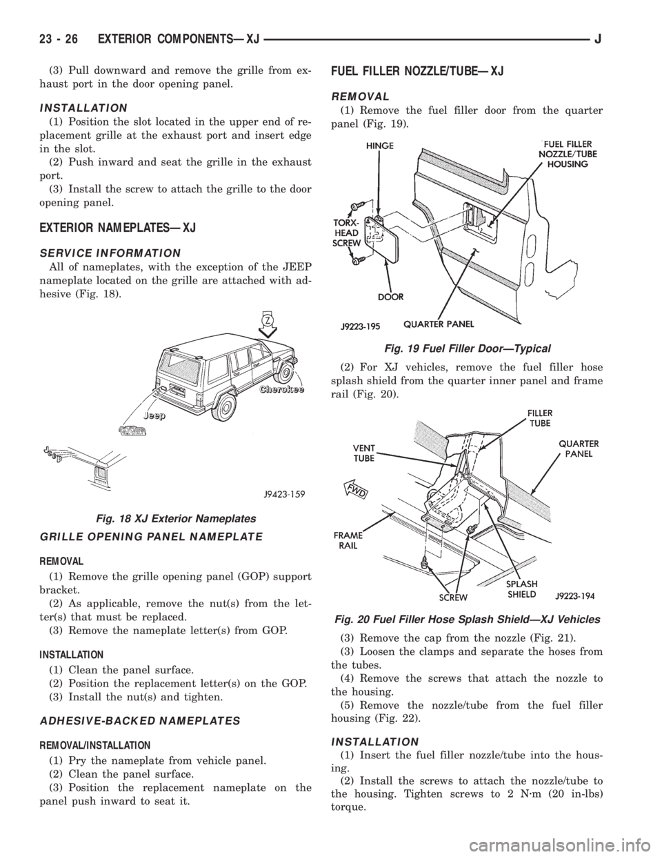
hesive (Fig. 18).
GRILLE OPENING PANEL NAMEPLATE
REMOVAL
(1) Remove the grille opening panel (GOP) support
bracket.
(2) As applicable, remove the nut(s) from the let-
ter(s) that must be replaced.
(3) Remove the nameplate letter(s) from GOP.
INSTALLATION
(1) Clean the panel surface.
(2) Position the replacement letter(s) on the GOP.
(3) Install the nut(s) and tighten.
ADHESIVE-BACKED NAMEPLATES
REMOVAL/INSTALLATION
(1) Pry the nameplate from vehicle panel.
(2) Clean the panel surface.
(3) Position the replacement nameplate on the
panel push inward to seat it.
FUEL FILLER NOZZLE/TUBEÐXJ
REMOVAL
(1) Remove the fuel filler door from the quarter
panel (Fig. 19).
(2) For XJ vehicles, remove the fuel filler hose
splash shield from the quarter inner panel and frame
rail (Fig. 20).
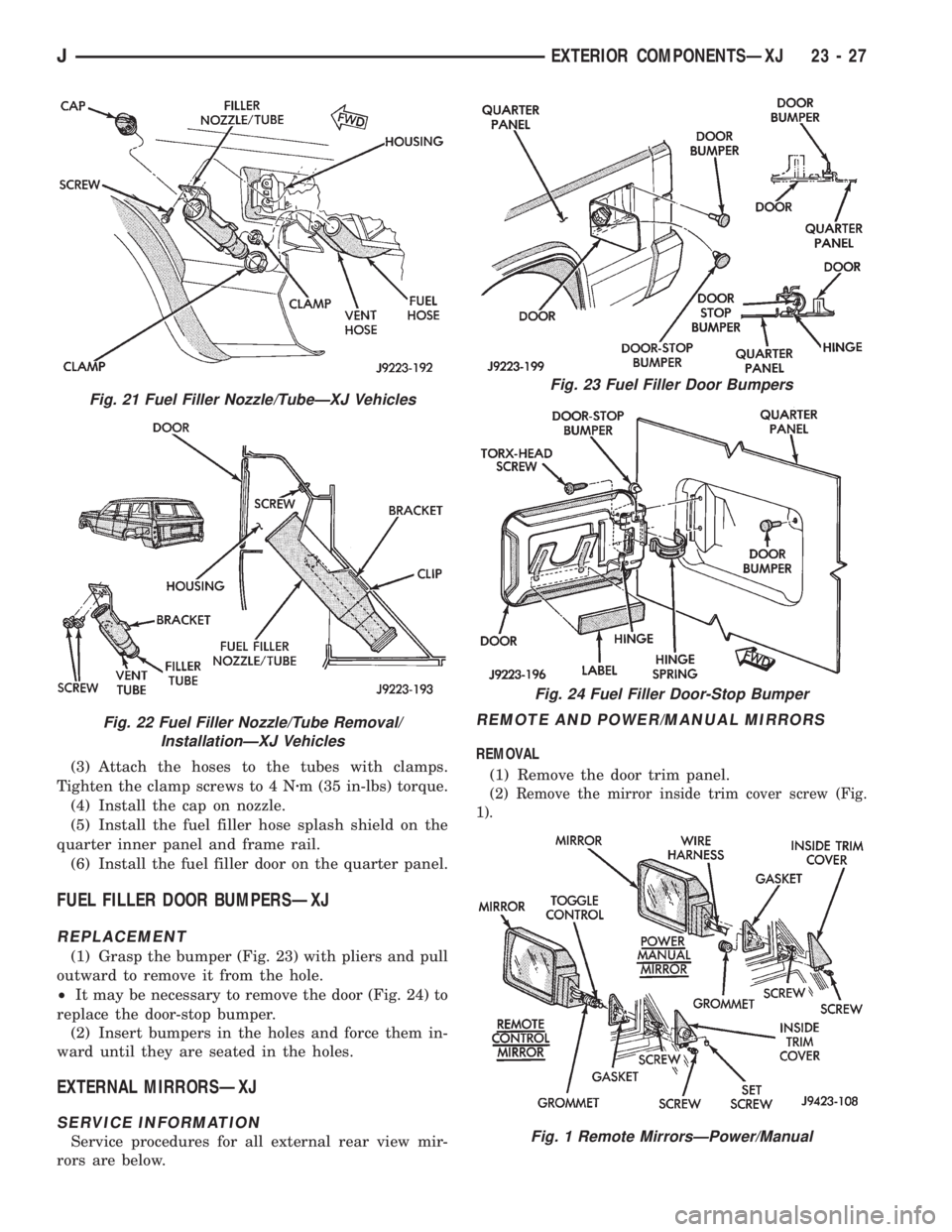
(3) Remove the cap from the nozzle (Fig. 21).
(3) Loosen the clamps and separate the hoses from
the tubes.
(4) Remove the screws that attach the nozzle to
the housing.
(5) Remove the nozzle/tube from the fuel filler
housing (Fig. 22).
INSTALLATION
(1) Insert the fuel filler nozzle/tube into the hous-
ing.
(2) Install the screws to attach the nozzle/tube to
the housing. Tighten screws to 2 Nzm (20 in-lbs)
torque.
Fig. 18 XJ Exterior Nameplates
Fig. 19 Fuel Filler DoorÐTypical
Fig. 20 Fuel Filler Hose Splash ShieldÐXJ Vehicles
23 - 26 EXTERIOR COMPONENTSÐXJJ
Page 1945 of 2158
(3) Attach the hoses to the tubes with clamps.
Tighten the clamp screws to 4 Nzm (35 in-lbs) torque.
(4) Install the cap on nozzle.
(5) Install the fuel filler hose splash shield on the
quarter inner panel and frame rail.
(6) Install the fuel filler door on the quarter panel.
FUEL FILLER DOOR BUMPERSÐXJ
REPLACEMENT
(1) Grasp the bumper (Fig. 23) with pliers and pull
outward to remove it from the hole.
²It may be necessary to remove the door (Fig. 24) to
replace the door-stop bumper.
(2) Insert bumpers in the holes and force them in-
ward until they are seated in the holes.
EXTERNAL MIRRORSÐXJ
SERVICE INFORMATION
Service procedures for all external rear view mir-
rors are below.
REMOTE AND POWER/MANUAL MIRRORS
REMOVAL
(1) Remove the door trim panel.
(2) Remove the mirror inside trim cover screw (Fig.
1).
Fig. 21 Fuel Filler Nozzle/TubeÐXJ Vehicles
Fig. 22 Fuel Filler Nozzle/Tube Removal/
InstallationÐXJ Vehicles
Fig. 23 Fuel Filler Door Bumpers
Fig. 24 Fuel Filler Door-Stop Bumper
Fig. 1 Remote MirrorsÐPower/Manual
JEXTERIOR COMPONENTSÐXJ 23 - 27
Page 1947 of 2158
INSTALLATION
(1) Install 3M 06379 double-sided tape, or an
equivalent on skid strips.
(2) Remove the backing from the double-sided
tape, align each skid strip on the roof, and position it
on the roof panel (Fig. 5).
(3) Verify that each skid strip is properly aligned.
(4) Press each skid strip onto the roof panel with a
roller (or use hand pressure).
To prevent water leaks, apply 3M Drip-Chek
Sealant, or equivalent.
(5) Position the luggage rack on the roof with the
screw holes aligned.
(6) Install and tighten the slide rail screws to 3
Nzm (28 in-lbs) torque.
Fig. 5 Skid Strip Installation
JEXTERIOR COMPONENTSÐXJ 23 - 29
Page 1953 of 2158
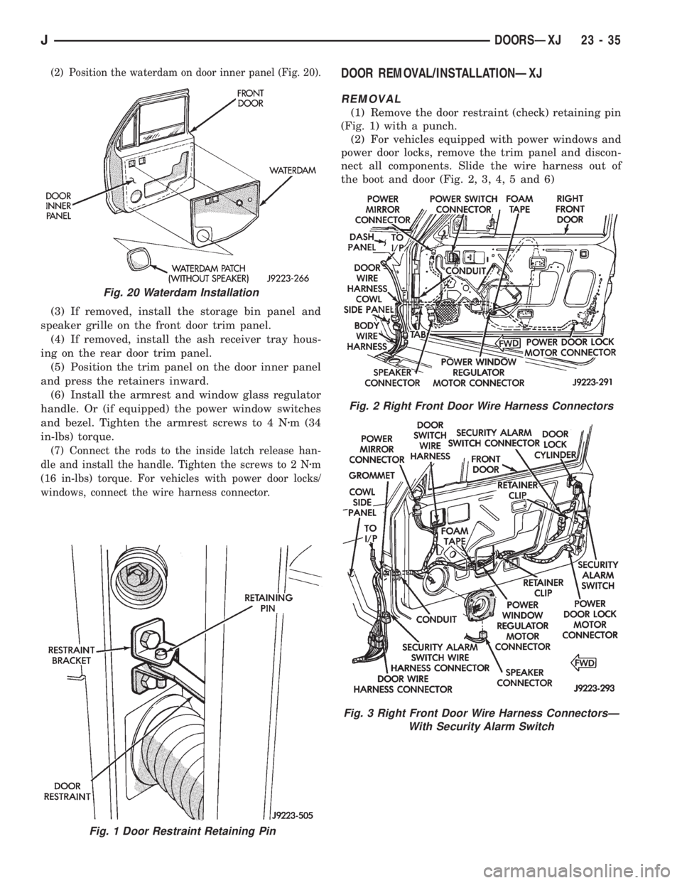
(2) Position the waterdam on door inner panel (Fig. 20).
(3) If removed, install the storage bin panel and
speaker grille on the front door trim panel.
(4) If removed, install the ash receiver tray hous-
ing on the rear door trim panel.
(5) Position the trim panel on the door inner panel
and press the retainers inward.
(6) Install the armrest and window glass regulator
handle. Or (if equipped) the power window switches
and bezel. Tighten the armrest screws to 4 Nzm (34
in-lbs) torque.
(7) Connect the rods to the inside latch release han-
dle and install the handle. Tighten the screws to 2 Nzm
(16 in-lbs) torque. For vehicles with power door locks/
windows, connect the wire harness connector.
DOOR REMOVAL/INSTALLATIONÐXJ
REMOVAL
(1) Remove the door restraint (check) retaining pin
(Fig. 1) with a punch.
(2) For vehicles equipped with power windows and
power door locks, remove the trim panel and discon-
nect all components. Slide the wire harness out of
the boot and door (Fig. 2, 3, 4, 5 and 6)
Fig. 1 Door Restraint Retaining Pin
Fig. 20 Waterdam Installation
Fig. 2 Right Front Door Wire Harness Connectors
Fig. 3 Right Front Door Wire Harness ConnectorsÐ
With Security Alarm Switch
JDOORSÐXJ 23 - 35
Page 1955 of 2158
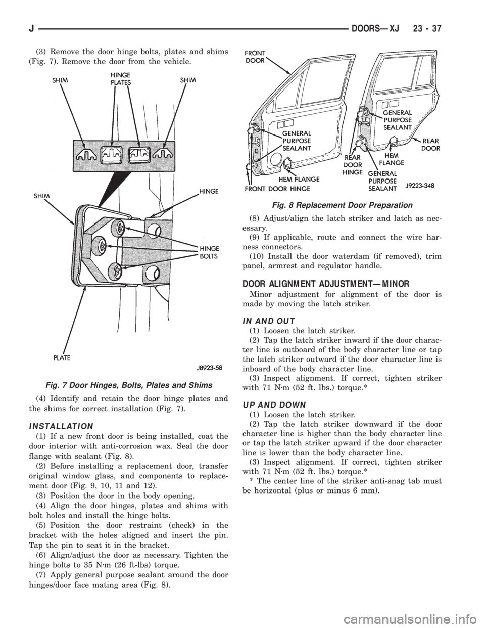
(3) Remove the door hinge bolts, plates and shims
(Fig. 7). Remove the door from the vehicle.
(4) Identify and retain the door hinge plates and
the shims for correct installation (Fig. 7).
INSTALLATION
(1) If a new front door is being installed, coat the
door interior with anti-corrosion wax. Seal the door
flange with sealant (Fig. 8).
(2) Before installing a replacement door, transfer
original window glass, and components to replace-
ment door (Fig. 9, 10, 11 and 12).
(3) Position the door in the body opening.
(4) Align the door hinges, plates and shims with
bolt holes and install the hinge bolts.
(5) Position the door restraint (check) in the
bracket with the holes aligned and insert the pin.
Tap the pin to seat it in the bracket.
(6) Align/adjust the door as necessary. Tighten the
hinge bolts to 35 Nzm (26 ft-lbs) torque.
(7) Apply general purpose sealant around the door
hinges/door face mating area (Fig. 8).(8) Adjust/align the latch striker and latch as nec-
essary.
(9) If applicable, route and connect the wire har-
ness connectors.
(10) Install the door waterdam (if removed), trim
panel, armrest and regulator handle.
DOOR ALIGNMENT ADJUSTMENTÐMINOR
Minor adjustment for alignment of the door is
made by moving the latch striker.
IN AND OUT
(1) Loosen the latch striker.
(2) Tap the latch striker inward if the door charac-
ter line is outboard of the body character line or tap
the latch striker outward if the door character line is
inboard of the body character line.
(3) Inspect alignment. If correct, tighten striker
with 71 Nzm (52 ft. lbs.) torque.*
UP AND DOWN
(1) Loosen the latch striker.
(2) Tap the latch striker downward if the door
character line is higher than the body character line
or tap the latch striker upward if the door character
line is lower than the body character line.
(3) Inspect alignment. If correct, tighten striker
with 71 Nzm (52 ft. lbs.) torque.*
* The center line of the striker anti-snag tab must
be horizontal (plus or minus 6 mm).
Fig. 7 Door Hinges, Bolts, Plates and Shims
Fig. 8 Replacement Door Preparation
JDOORSÐXJ 23 - 37
Page 1959 of 2158
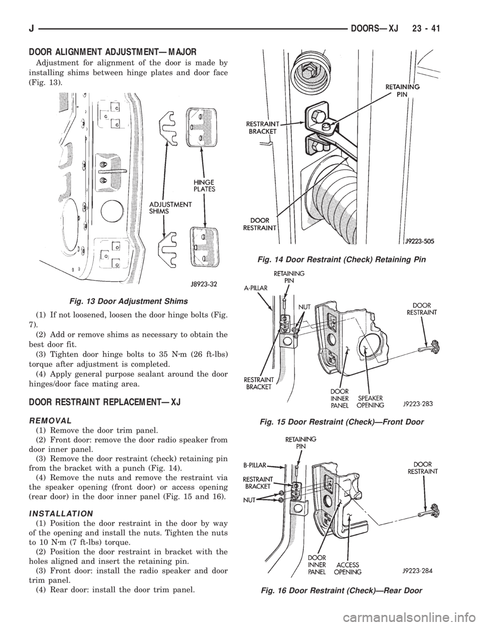
DOOR ALIGNMENT ADJUSTMENTÐMAJOR
Adjustment for alignment of the door is made by
installing shims between hinge plates and door face
(Fig. 13).
(1) If not loosened, loosen the door hinge bolts (Fig.
7).
(2) Add or remove shims as necessary to obtain the
best door fit.
(3) Tighten door hinge bolts to 35 Nzm (26 ft-lbs)
torque after adjustment is completed.
(4) Apply general purpose sealant around the door
hinges/door face mating area.
DOOR RESTRAINT REPLACEMENTÐXJ
REMOVAL
(1) Remove the door trim panel.
(2) Front door: remove the door radio speaker from
door inner panel.
(3) Remove the door restraint (check) retaining pin
from the bracket with a punch (Fig. 14).
(4) Remove the nuts and remove the restraint via
the speaker opening (front door) or access opening
(rear door) in the door inner panel (Fig. 15 and 16).
INSTALLATION
(1) Position the door restraint in the door by way
of the opening and install the nuts. Tighten the nuts
to 10 Nzm (7 ft-lbs) torque.
(2) Position the door restraint in bracket with the
holes aligned and insert the retaining pin.
(3) Front door: install the radio speaker and door
trim panel.
(4) Rear door: install the door trim panel.
Fig. 14 Door Restraint (Check) Retaining Pin
Fig. 15 Door Restraint (Check)ÐFront Door
Fig. 16 Door Restraint (Check)ÐRear Door
Fig. 13 Door Adjustment Shims
JDOORSÐXJ 23 - 41
Page 1961 of 2158
(4) Tighten the regulator-to-glass screw to 4 Nzm
(36 in-lbs) torque.
(5) Install the glass channel bottom screw (Fig.
17). Tighten screw to 9 Nzm (7 ft-lbs) torque.(6) Attach the door waterdam to the door inner
panel with sealant.
(7) Install the trim panel.
FRONT DOOR WINDOW GLASSÐXJ
REMOVAL
(1) Remove the door trim panel and waterdam.
(2) Remove the window glass channel hardware,
beltline molding and weatherstrip seals (Fig. 25 and
26).
(3) Remove the glass channel bottom screw.
(4) Remove the regulator-to-window glass screw,
bushing and retainer (Fig. 20).
(5) Lift the glass upward and out of the door.
Fig. 21 Manual Regulator InstallationÐUpper Rivets
Fig. 22 Manual Regulator InstallationÐLower Rivets
and Glass Retaining Screw
Fig. 23 Power Regulator InstallationÐUpper Rivets
Fig. 24 Power Regulator InstallationÐLower Rivets
Fig. 25 Front Door Beltline Molding and
Weatherstrip Seals
JDOORSÐXJ 23 - 43
Page 1962 of 2158
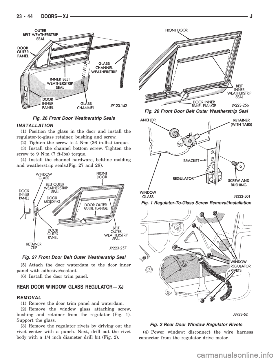
INSTALLATION
(1) Position the glass in the door and install the
regulator-to-glass retainer, bushing and screw.
(2) Tighten the screw to 4 Nzm (36 in-lbs) torque.
(3) Install the channel bottom screw. Tighten the
screw to 9 Nzm (7 ft-lbs) torque.
(4) Install the channel hardware, beltline molding
and weatherstrip seals.(Fig. 27 and 28).
(5) Attach the door waterdam to the door inner
panel with adhesive/sealant.
(6) Install the door trim panel.
REAR DOOR WINDOW GLASS REGULATORÐXJ
REMOVAL
(1) Remove the door trim panel and waterdam.
(2) Remove the window glass attaching screw,
bushing and retainer from the regulator (Fig. 1).
Support the glass.
(3) Remove the regulator rivets by driving out the
rivet center with a punch. Next, drill out the rivet
body with a 1/4 inch diameter drill bit (Fig. 2).(4) Power window: disconnect the wire harness
connector from the regulator drive motor.
Fig. 26 Front Door Weatherstrip Seals
Fig. 27 Front Door Belt Outer Weatherstrip Seal
Fig. 28 Front Door Belt Outer Weatherstrip Seal
Fig. 1 Regulator-To-Glass Screw Removal/Installation
Fig. 2 Rear Door Window Regulator Rivets
23 - 44 DOORSÐXJJ