1995 JEEP YJ torque
[x] Cancel search: torquePage 1928 of 2158
(6) Attach the latch release cable to the clips.
(7) Connect the latches to the latch rod and posi-
tion them on the hood.
(8) Install the screws to attach the latches to the
hood.
Tighten the screws to 9 Nzm (77 in-lbs) torque.
(9) Position the safety latch on the hood and install
the attaching nuts. Tighten the screws to 13 Nzm
(115 in-lbs) torque.
(10) Test latch release cable and latches for proper
operation.
(11) Connect the underhood lamp wire harness
connector.
(12) Inspect the hood for proper alignment and ad-
just as necessary.
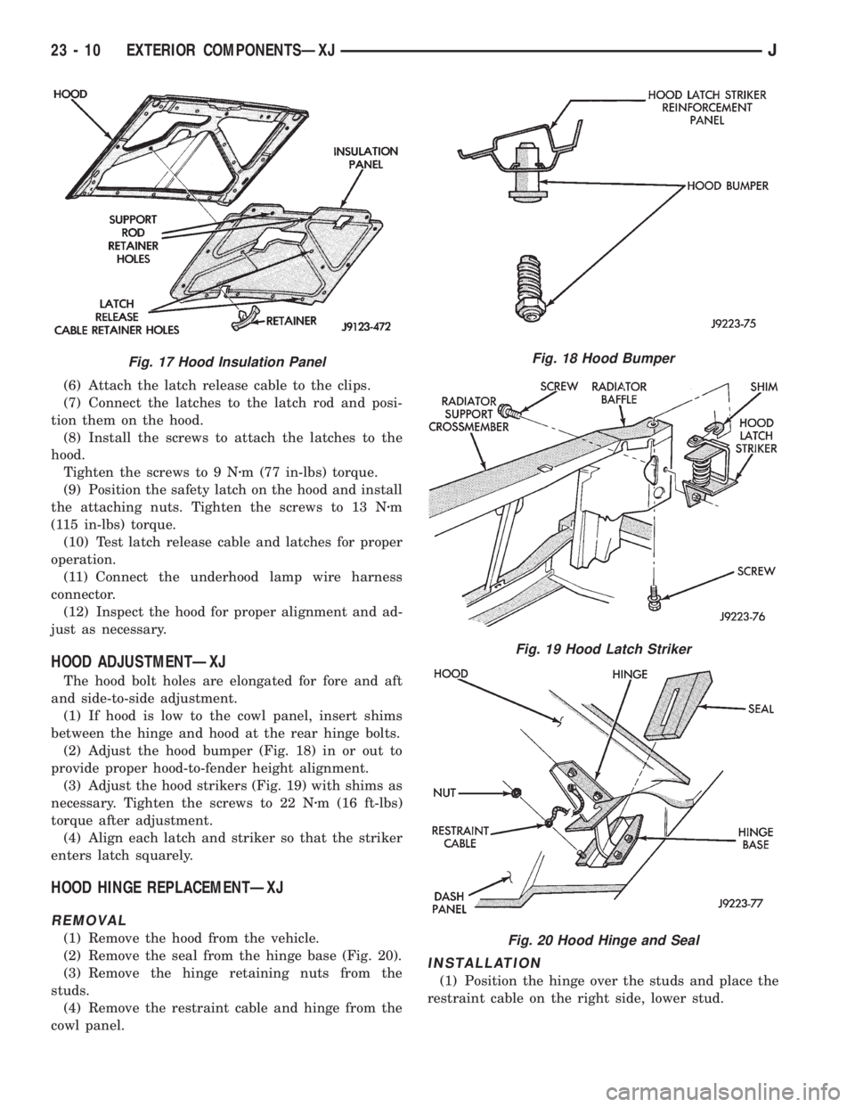
HOOD ADJUSTMENTÐXJ
The hood bolt holes are elongated for fore and aft
and side-to-side adjustment.
(1) If hood is low to the cowl panel, insert shims
between the hinge and hood at the rear hinge bolts.
(2) Adjust the hood bumper (Fig. 18) in or out to
provide proper hood-to-fender height alignment.
(3) Adjust the hood strikers (Fig. 19) with shims as
necessary. Tighten the screws to 22 Nzm (16 ft-lbs)
torque after adjustment.
(4) Align each latch and striker so that the striker
enters latch squarely.
HOOD HINGE REPLACEMENTÐXJ
REMOVAL
(1) Remove the hood from the vehicle.
(2) Remove the seal from the hinge base (Fig. 20).
(3) Remove the hinge retaining nuts from the
studs.
(4) Remove the restraint cable and hinge from the
cowl panel.
INSTALLATION
(1) Position the hinge over the studs and place the
restraint cable on the right side, lower stud.
Fig. 17 Hood Insulation PanelFig. 18 Hood Bumper
Fig. 19 Hood Latch Striker
Fig. 20 Hood Hinge and Seal
23 - 10 EXTERIOR COMPONENTSÐXJJ
Page 1929 of 2158
(2) Install the hinge nuts on the studs. Tighten the
restraint cable nut to 4 Nzm (38 in-lbs) torque.
Tighten the remaining nuts to 9 Nzm (77 in-lbs)
torque.
If a replacement hinge seal is being installed,
position it around the hinge arm, force it
against the hinge base.
(3) Position the hinge seal around the hinge arm
and on hinge base.
(4) Install the hood.
(5) Adjust the hood as necessary.
HOOD LATCH REPLACEMENTÐXJ
REMOVAL
(1) Remove the screw that attaches the latch to the
hood inner panel (Fig. 15).
(2) Disconnect the latch from the hood and latch
connecting rod. Remove the latch from the hood.
INSTALLATION
(1) Connect the latch to the latch connecting rod
and position it on the hood inner panel.
(2) Install the screw that attaches the latch to the
hood inner panel.
(3) Tighten the screw to 9 Nzm (77 in-lbs) torque.
(4) Test the operation of the latch release cable and
latch.
HOOD LATCH STRIKER REPLACEMENTÐXJ
REMOVE
(1) Remove the grille opening panel (GOP).
(2) Remove the screws that attach the striker to
the radiator baffle (Fig. 19).
(3) Remove the striker and shims from the baffle.
INSTALLATION
(1) Position the shims and striker on the radiator
baffle and install the screws.
(2) Tighten the screws to 21 Nzm (15 ft-lbs) torque.
(3) Test the striker/hood alignment by opening and
closing the hood several times. Adjust the striker, if
necessary.
LATCH RELEASE CABLE REPLACEMENTÐXJ
REMOVAL
(1) Drill out the bellcrank to hood rivet heads and
remove the rivets (Fig. 14).
(2) Disconnect the bellcrank from the latch rod and
the latch release cable. Remove the bellcrank from
the hood.
(3) Disconnect the latch release cable from the
clips on the hood.
(4) Remove the left cowl side trim panel.
(5) Remove the cable bracket screws from the cowl
side panel.(6) Pull the cable through the dash panel and re-
move it from under the instrument panel.
INSTALLATION
(1) Insert the replacement cable end through the
hole in the dash panel into the engine compartment.
(2) Pull the cable forward and seat the grommet in
the dash panel.
(3) Position the cable bracket on the cowl side
panel and install the screws. Tighten the screws to
13 Nzm (111 in-lbs) torque.
(4) Install the left cowl side trim panel.
(5) Connect the cable and latch rod to the
bellcrank.
(6) Position the bellcrank on the hood and install
the rivets.
(7) Attach the cable to the clips.
(8) Test release the cable for proper operation.
SAFETY LATCH STRIKER REPLACEMENTÐXJ
REMOVAL
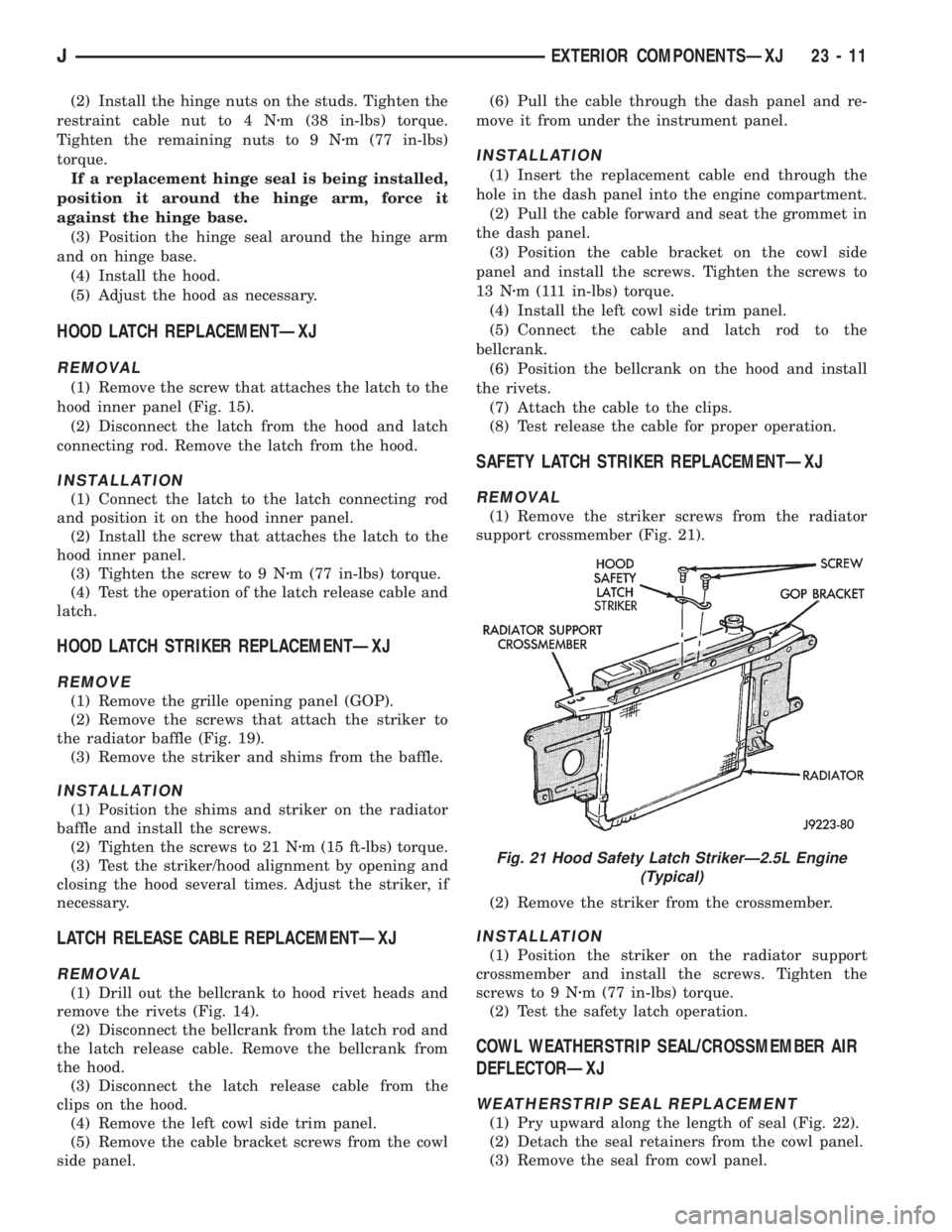
(1) Remove the striker screws from the radiator
support crossmember (Fig. 21).
(2) Remove the striker from the crossmember.
INSTALLATION
(1) Position the striker on the radiator support
crossmember and install the screws. Tighten the
screws to 9 Nzm (77 in-lbs) torque.
(2) Test the safety latch operation.
COWL WEATHERSTRIP SEAL/CROSSMEMBER AIR
DEFLECTORÐXJ
WEATHERSTRIP SEAL REPLACEMENT
(1) Pry upward along the length of seal (Fig. 22).
(2) Detach the seal retainers from the cowl panel.
(3) Remove the seal from cowl panel.
Fig. 21 Hood Safety Latch StrikerÐ2.5L Engine
(Typical)
JEXTERIOR COMPONENTSÐXJ 23 - 11
Page 1930 of 2158
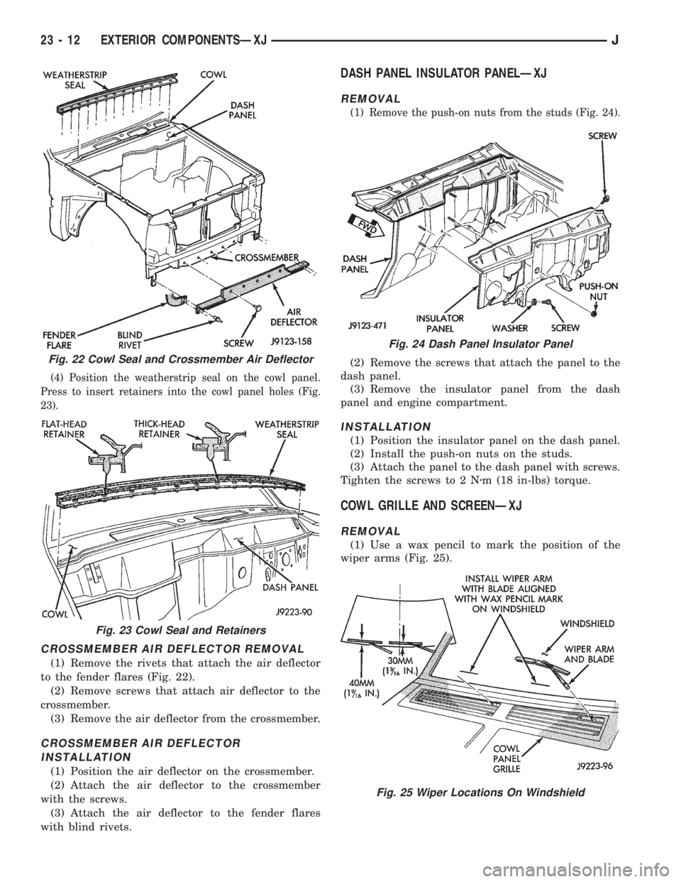
(4) Position the weatherstrip seal on the cowl panel.
Press to insert retainers into the cowl panel holes (Fig.
23).
CROSSMEMBER AIR DEFLECTOR REMOVAL
(1) Remove the rivets that attach the air deflector
to the fender flares (Fig. 22).
(2) Remove screws that attach air deflector to the
crossmember.
(3) Remove the air deflector from the crossmember.
CROSSMEMBER AIR DEFLECTOR
INSTALLATION
(1) Position the air deflector on the crossmember.
(2) Attach the air deflector to the crossmember
with the screws.
(3) Attach the air deflector to the fender flares
with blind rivets.
DASH PANEL INSULATOR PANELÐXJ
REMOVAL
(1) Remove the push-on nuts from the studs (Fig. 24).
(2) Remove the screws that attach the panel to the
dash panel.
(3) Remove the insulator panel from the dash
panel and engine compartment.
INSTALLATION
(1) Position the insulator panel on the dash panel.
(2) Install the push-on nuts on the studs.
(3) Attach the panel to the dash panel with screws.
Tighten the screws to 2 Nzm (18 in-lbs) torque.
COWL GRILLE AND SCREENÐXJ
REMOVAL
(1) Use a wax pencil to mark the position of the
wiper arms (Fig. 25).
Fig. 22 Cowl Seal and Crossmember Air Deflector
Fig. 23 Cowl Seal and Retainers
Fig. 24 Dash Panel Insulator Panel
Fig. 25 Wiper Locations On Windshield
23 - 12 EXTERIOR COMPONENTSÐXJJ
Page 1931 of 2158
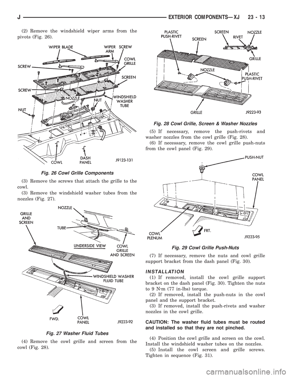
(2) Remove the windshield wiper arms from the
pivots (Fig. 26).
(3) Remove the screws that attach the grille to the
cowl.
(3) Remove the windshield washer tubes from the
nozzles (Fig. 27).
(4) Remove the cowl grille and screen from the
cowl (Fig. 28).(5) If necessary, remove the push-rivets and
washer nozzles from the cowl grille (Fig. 28).
(6) If necessary, remove the cowl grille push-nuts
from the cowl panel (Fig. 29).
(7) If necessary, remove the nuts and cowl grille
support bracket from the dash panel (Fig. 30).
INSTALLATION
(1) If removed, install the cowl grille support
bracket on the dash panel (Fig. 30). Tighten the nuts
to9Nzm (77 in-lbs) torque.
(2) If removed, install the push-nuts in the cowl
panel and the support bracket.
(3) If removed, install the push-rivets and washer
nozzles in the cowl grille.
CAUTION: The washer fluid tubes must be routed
and installed so that they are not pinched.
(4) Position the cowl grille and screen on the cowl.
Install the windshield washer tubes on the nozzles.
(5) Install the cowl screen and grille screws.
Tighten in sequence (Fig. 31).
Fig. 26 Cowl Grille Components
Fig. 27 Washer Fluid Tubes
Fig. 28 Cowl Grille, Screen & Washer Nozzles
Fig. 29 Cowl Grille Push-Nuts
JEXTERIOR COMPONENTSÐXJ 23 - 13
Page 1932 of 2158
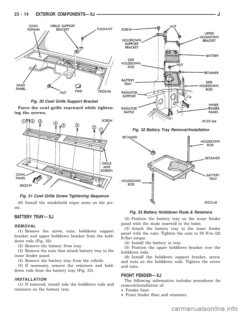
Force the cowl grille rearward while tighten-
ing the screws.
(6) Install the windshield wiper arms on the piv-
ots.
BATTERY TRAYÐXJ
REMOVAL
(1) Remove the screw, nuts, holddown support
bracket and upper holddown bracket from the hold-
down rods (Fig. 32).
(2) Remove the battery from tray.
(3) Remove the nuts that attach battery tray to the
inner fender panel.
(4) Remove the battery tray from the vehicle.
(5) If necessary, remove the retainers and hold-
down rods from the battery tray (Fig. 33).
INSTALLATION
(1) If removed, install side the holddown rods and
retainers on the battery tray.(2) Position the battery tray on the inner fender
panel with the studs inserted in the holes.
(3) Attach the battery tray to the inner fender
panel with the nuts. Tighten the nuts to 30 Nzm (22
ft-lbs) torque.
(4) Install the battery in tray.
(5) Position the upper holddown bracket over the
holddown rods.
(6) Install the holddown support bracket, screw,
and nuts on the holddown rods. Tighten the screw
and nuts.
FRONT FENDERÐXJ
The following information includes procedures for
removal/installation of:
²Fender liner.
²Front fender flare and retainers.
Fig. 30 Cowl Grille Support Bracket
Fig. 31 Cowl Grille Screw Tightening Sequence
Fig. 32 Battery Tray Removal/Installation
Fig. 33 Battery Holddown Rods & Retainers
23 - 14 EXTERIOR COMPONENTSÐXJJ
Page 1936 of 2158
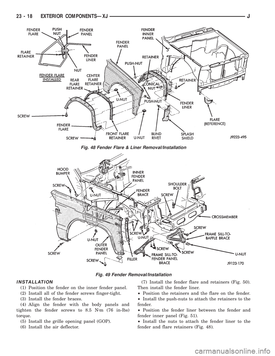
INSTALLATION
(1) Position the fender on the inner fender panel.
(2) Install all of the fender screws finger-tight.
(3) Install the fender braces.
(4) Align the fender with the body panels and
tighten the fender screws to 8.5 Nzm (76 in-lbs)
torque.
(5) Install the grille opening panel (GOP).
(6) Install the air deflector.(7) Install the fender flare and retainers (Fig. 50).
Then install the fender liner.
²Position the retainers and the flare on the fender.
²Install the push-nuts to attach the retainers to the
fender.
²Position the fender liner between the fender and
fender inner panel (Fig. 51).
²Install the nuts to attach the fender liner to the
fender and flare retainers (Fig. 48).
Fig. 48 Fender Flare & Liner Removal/Installation
Fig. 49 Fender Removal/Installation
23 - 18 EXTERIOR COMPONENTSÐXJJ
Page 1937 of 2158
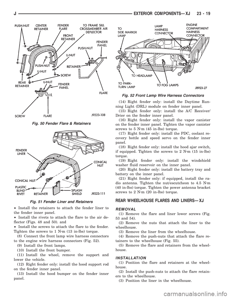
²Install the retainers to attach the fender liner to
the fender inner panel.
²Install the rivets to attach the flare to the air de-
flector (Figs. 48 and 50). and
²Install the screws to attach the flare to the fender.
Tighten the screws to 1 Nzm (13 in-lbs) torque.
(8) Connect the front lamp wire harness connectors
to the engine wire harness connectors (Fig. 52).
(9) Install the front lamps.
(10) Install the front bumper.
(11) Install the wheel, remove the support and
lower the vehicle.
(12) Right fender only: install the hood support rod
on the fender inner panel.
(13) Install the hood bumper on the fender inner
panel.(14) Right fender only: install the Daytime Run-
ning Light (DRL) module on fender inner panel.
(15) Right fender only: install the A/C Receiver/
Drier on the fender inner panel.
(16) Right fender only: install the vapor canister
on the fender inner panel. Tighten the vapor canister
screws to 5 Nzm (45 in-lbs) torque.
(17) Right fender only: install the PDC, coolant re-
covery bottle and speed servo on the fender inner
panel.
(18) Right fender only: install the hood ajar switch,
if equipped. Tighten the screws to 2 Nzm (15 in-lbs)
torque.
(19) Right fender only: install the windshield
washer fluid reservoir on the inner panel.
(20) Right fender only: install the battery tray and
battery on the inner panel.
(21) Right fender only: if equipped, install the ra-
dio antenna. Tighten the nut/escutcheon to 4.5 Nzm
(40 in-lbs) torque. Tighten the power antenna bracket
screws to 2 Nzm (20 in-lbs) torque.
REAR WHEELHOUSE FLARES AND LINERSÐXJ
REMOVAL
(1) Remove the flare and liner lower screws (Fig.
53 and 54).
(2) Remove the nuts that attach the liner to the
wheelhouse.
(3) Remove the liner from the wheelhouse.
(4) Remove the push-nuts that attach the flare re-
tainers to the wheelhouse (Fig. 55).
(5) Remove the flare and retainers from the wheel-
house.
INSTALLATION
(1) Position the flare and retainers at the wheel-
house.
(2) Install the push-nuts to attach the flare retain-
ers to the wheelhouse.
(3) Position the liner in the wheelhouse.
Fig. 50 Fender Flare & Retainers
Fig. 51 Fender Liner and Retainers
Fig. 52 Front Lamp Wire Harness Connectors
JEXTERIOR COMPONENTSÐXJ 23 - 19
Page 1938 of 2158
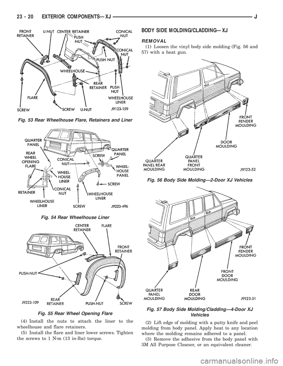
(4) Install the nuts to attach the liner to the
wheelhouse and flare retainers.
(5) Install the flare and liner lower screws. Tighten
the screws to 1 Nzm (13 in-lbs) torque.
BODY SIDE MOLDING/CLADDINGÐXJ
REMOVAL
(1) Loosen the vinyl body side molding (Fig. 56 and
57) with a heat gun.
(2) Lift edge of molding with a putty knife and peel
molding from body panel. Apply heat to any location
where the molding remains adhered to a panel.
(3) Remove the adhesive from the body panel with
3M All Purpose Cleaner, or an equivalent cleaner.
Fig. 53 Rear Wheelhouse Flare, Retainers and Liner
Fig. 54 Rear Wheelhouse Liner
Fig. 55 Rear Wheel Opening Flare
Fig. 56 Body Side MoldingÐ2-Door XJ Vehicles
Fig. 57 Body Side Molding/CladdingÐ4-Door XJ
Vehicles
23 - 20 EXTERIOR COMPONENTSÐXJJ