1995 JEEP YJ torque
[x] Cancel search: torquePage 2012 of 2158
INSTALLATION
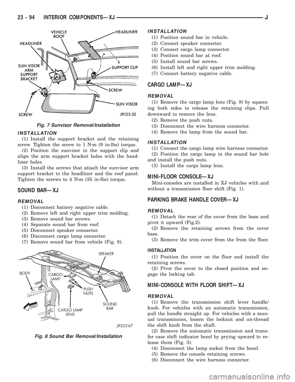
(1) Install the support bracket and the retaining
screw. Tighten the screw to 1 Nzm (9 in-lbs) torque.
(2) Position the sunvisor in the support clip and
align the arm support bracket holes with the head-
liner holes.
(3) Install the screws that attach the sunvisor arm
support bracket to the headliner and the roof panel.
Tighten the screws to 4 Nzm (35 in-lbs) torque.
SOUND BARÐXJ
REMOVAL
(1) Disconnect battery negative cable.
(2) Remove left and right upper trim molding.
(3) Remove sound bar screws.
(4) Separate sound bar from roof.
(5) Disconnect speaker connector.
(6) Disconnect cargo lamp connector.
(7) Remove sound bar from vehicle (Fig. 8).
INSTALLATION
(1) Position sound bar in vehicle.
(2) Connect speaker connecter.
(3) Connect cargo lamp connector.
(4) Position sound bar at roof.
(5) Install sound bar screws.
(6) Install left and right upper trim molding.
(7) Connect battery negative cable.
CARGO LAMPÐXJ
REMOVAL
(1) Remove the cargo lamp lens (Fig. 8) by squeez-
ing both sides to release the retaining clips. Pull
downward to remove the lens.
(2) Remove the push nuts.
(3) Disconnect the wire harness connector.
(4) Remove the lamp from the sound bar.
INSTALLATION
(1) Connect the cargo lamp wire harness connector.
(2) Position the cargo lamp in the sound bar hole
and install the push nuts.
(3) Install the cargo lamp lens.
MINI-FLOOR CONSOLEÐXJ
Mini-consoles are installed in XJ vehicles with and
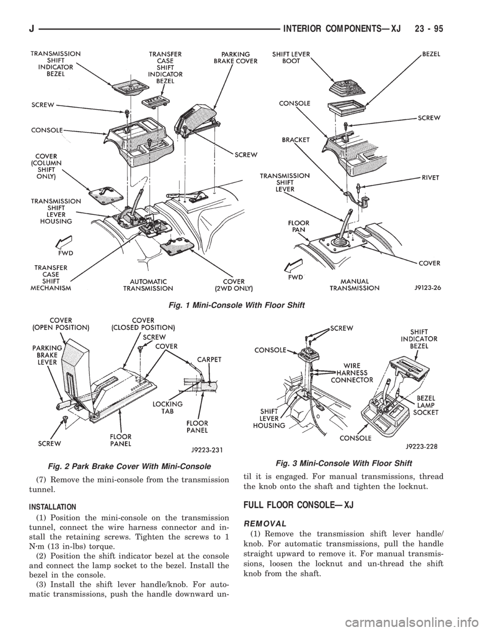
without a transmission floor shift (Fig. 1).
PARKING BRAKE HANDLE COVERÐXJ
REMOVAL
(1) Detach the rear of the cover from the base and
pivot it upward (Fig.2).
(2) Remove the retaining screws from the cover
base.
(3) Remove the trim cover from the from the floor.
INSTALLATION
(1) Position the cover on the floor and install the
retaining screws.
(2) Pivot the cover to the closed position and en-
gage the locking tab.
MINI-CONSOLE WITH FLOOR SHIFTÐXJ
REMOVAL
(1) Remove the transmission shift lever handle/
knob. For vehicles with an automatic transmission,
pull the handle straight up. For vehicles with a man-
ual transmission, loosen the locknut and un-thread
the shift knob from the shaft.
(2) Remove the automatic transmission and trans-
fer case shift indicator bezel by prying upward to re-
lease them (Fig. 3).
(4) Disconnect the lamp socket from the bezel.
(5) Remove the console retaining screws.
(6) Disconnect the wire harness connector.
Fig. 7 Sunvisor Removal/Installation
Fig. 8 Sound Bar Removal/Installation
23 - 94 INTERIOR COMPONENTSÐXJJ
Page 2013 of 2158
(7) Remove the mini-console from the transmission
tunnel.
INSTALLATION
(1) Position the mini-console on the transmission
tunnel, connect the wire harness connector and in-
stall the retaining screws. Tighten the screws to 1
Nzm (13 in-lbs) torque.
(2) Position the shift indicator bezel at the console
and connect the lamp socket to the bezel. Install the
bezel in the console.
(3) Install the shift lever handle/knob. For auto-
matic transmissions, push the handle downward un-til it is engaged. For manual transmissions, thread
the knob onto the shaft and tighten the locknut.
FULL FLOOR CONSOLEÐXJ
REMOVAL
(1) Remove the transmission shift lever handle/
knob. For automatic transmissions, pull the handle
straight upward to remove it. For manual transmis-
sions, loosen the locknut and un-thread the shift
knob from the shaft.
Fig. 1 Mini-Console With Floor Shift
Fig. 2 Park Brake Cover With Mini-ConsoleFig. 3 Mini-Console With Floor Shift
JINTERIOR COMPONENTSÐXJ 23 - 95
Page 2015 of 2158
(4) Remove the cover retaining screws and remove
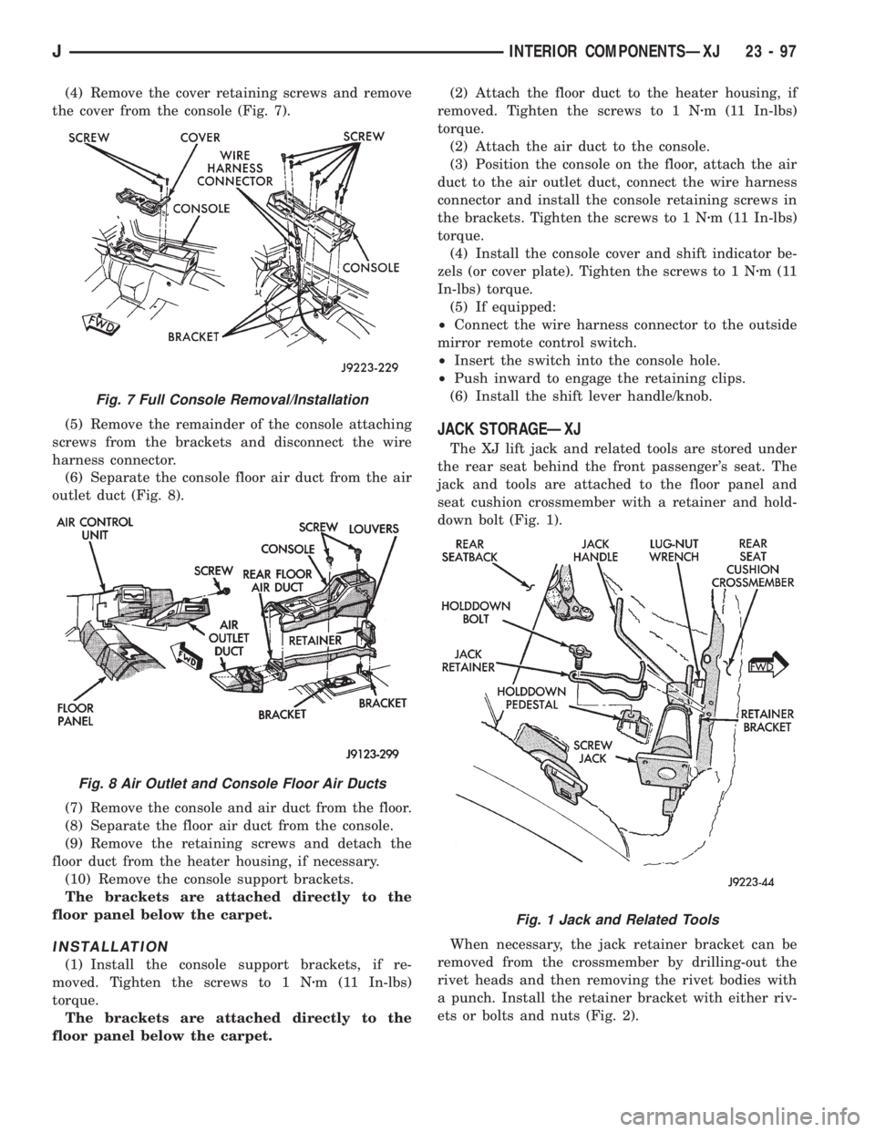
the cover from the console (Fig. 7).
(5) Remove the remainder of the console attaching
screws from the brackets and disconnect the wire
harness connector.
(6) Separate the console floor air duct from the air
outlet duct (Fig. 8).
(7) Remove the console and air duct from the floor.
(8) Separate the floor air duct from the console.
(9) Remove the retaining screws and detach the
floor duct from the heater housing, if necessary.
(10) Remove the console support brackets.
The brackets are attached directly to the
floor panel below the carpet.
INSTALLATION
(1) Install the console support brackets, if re-
moved. Tighten the screws to 1 Nzm (11 In-lbs)
torque.
The brackets are attached directly to the
floor panel below the carpet.(2) Attach the floor duct to the heater housing, if
removed. Tighten the screws to 1 Nzm (11 In-lbs)
torque.
(2) Attach the air duct to the console.
(3) Position the console on the floor, attach the air
duct to the air outlet duct, connect the wire harness
connector and install the console retaining screws in
the brackets. Tighten the screws to 1 Nzm (11 In-lbs)
torque.
(4) Install the console cover and shift indicator be-
zels (or cover plate). Tighten the screws to 1 Nzm(11
In-lbs) torque.
(5) If equipped:
²Connect the wire harness connector to the outside
mirror remote control switch.
²Insert the switch into the console hole.
²Push inward to engage the retaining clips.
(6) Install the shift lever handle/knob.
JACK STORAGEÐXJ
The XJ lift jack and related tools are stored under
the rear seat behind the front passenger's seat. The
jack and tools are attached to the floor panel and
seat cushion crossmember with a retainer and hold-
down bolt (Fig. 1).
When necessary, the jack retainer bracket can be
removed from the crossmember by drilling-out the
rivet heads and then removing the rivet bodies with
a punch. Install the retainer bracket with either riv-
ets or bolts and nuts (Fig. 2).
Fig. 7 Full Console Removal/Installation
Fig. 8 Air Outlet and Console Floor Air Ducts
Fig. 1 Jack and Related Tools
JINTERIOR COMPONENTSÐXJ 23 - 97
Page 2016 of 2158
SPARE TIRE/WHEEL HOLDDOWN AND FLOOR
BRACKETSÐXJ
REMOVAL
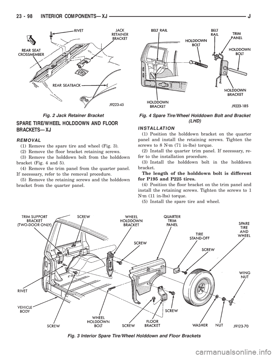
(1) Remove the spare tire and wheel (Fig. 3).
(2) Remove the floor bracket retaining screws.
(3) Remove the holddown bolt from the holddown
bracket (Fig. 4 and 5).
(4) Remove the trim panel from the quarter panel.
If necessary, refer to the removal procedure.
(5) Remove the retaining screws and the holddown
bracket from the quarter panel.
INSTALLATION
(1) Position the holddown bracket on the quarter
panel and install the retaining screws. Tighten the
screws to 8 Nzm (71 in-lbs) torque.
(2) Install the quarter trim panel. If necessary, re-
fer to the installation procedure.
(3) Install the holddown bolt in the holddown
bracket.
The length of the holddown bolt is different
for P195 and P225 tires.
(4) Position the floor bracket on the trim panel and
install the retaining screws. Tighten the screws to 1
Nzm (11 in-lbs) torque.
(5) Install the spare tire and wheel.
Fig. 3 Interior Spare Tire/Wheel Holddown and Floor Brackets
Fig. 2 Jack Retainer BracketFig. 4 Spare Tire/Wheel Holddown Bolt and Bracket
(LHD)
23 - 98 INTERIOR COMPONENTSÐXJJ
Page 2018 of 2158
REAR CARPET/MATÐXJ
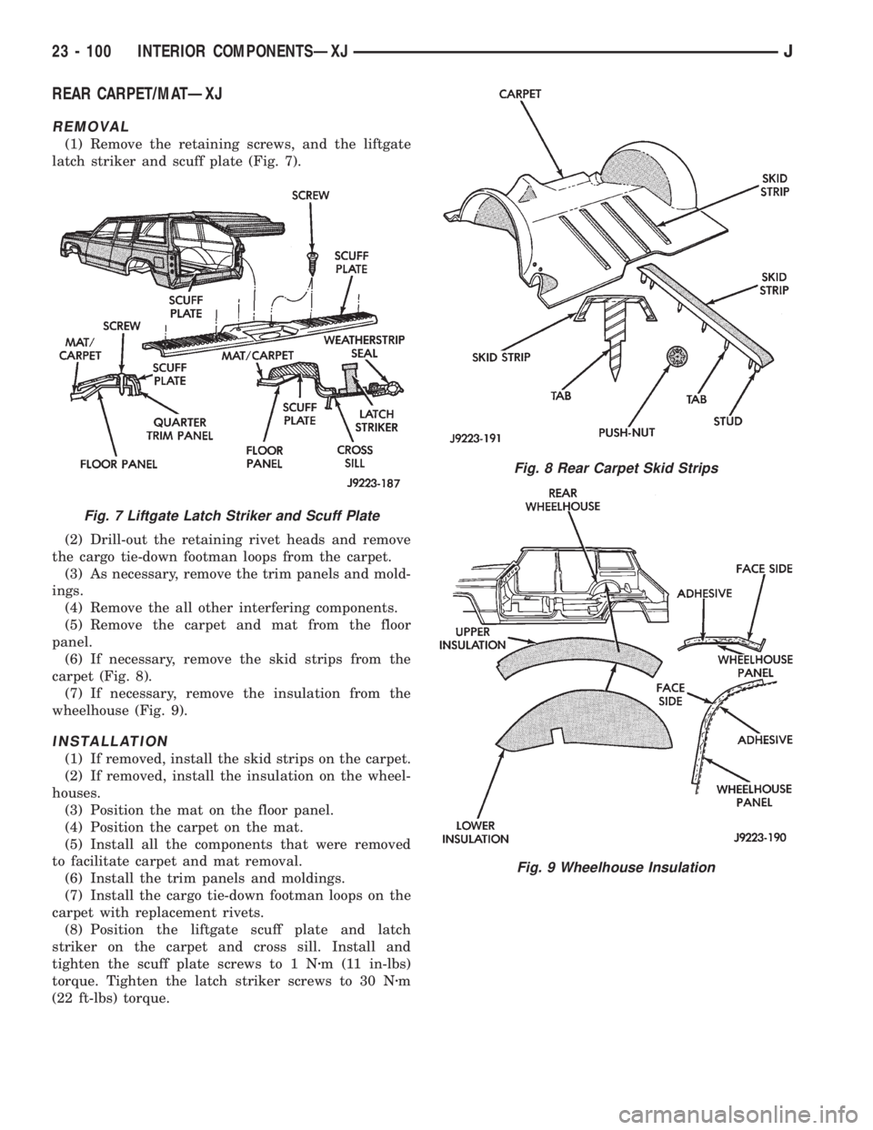
REMOVAL
(1) Remove the retaining screws, and the liftgate
latch striker and scuff plate (Fig. 7).
(2) Drill-out the retaining rivet heads and remove
the cargo tie-down footman loops from the carpet.
(3) As necessary, remove the trim panels and mold-
ings.
(4) Remove the all other interfering components.
(5) Remove the carpet and mat from the floor
panel.
(6) If necessary, remove the skid strips from the
carpet (Fig. 8).
(7) If necessary, remove the insulation from the
wheelhouse (Fig. 9).
INSTALLATION
(1) If removed, install the skid strips on the carpet.
(2) If removed, install the insulation on the wheel-
houses.
(3) Position the mat on the floor panel.
(4) Position the carpet on the mat.
(5) Install all the components that were removed
to facilitate carpet and mat removal.
(6) Install the trim panels and moldings.
(7) Install the cargo tie-down footman loops on the
carpet with replacement rivets.
(8) Position the liftgate scuff plate and latch
striker on the carpet and cross sill. Install and
tighten the scuff plate screws to 1 Nzm (11 in-lbs)
torque. Tighten the latch striker screws to 30 Nzm
(22 ft-lbs) torque.
Fig. 7 Liftgate Latch Striker and Scuff Plate
Fig. 8 Rear Carpet Skid Strips
Fig. 9 Wheelhouse Insulation
23 - 100 INTERIOR COMPONENTSÐXJJ
Page 2023 of 2158
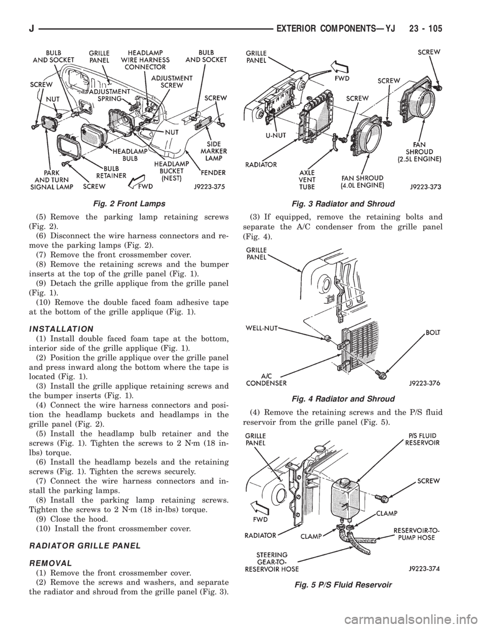
(5) Remove the parking lamp retaining screws
(Fig. 2).
(6) Disconnect the wire harness connectors and re-
move the parking lamps (Fig. 2).
(7) Remove the front crossmember cover.
(8) Remove the retaining screws and the bumper
inserts at the top of the grille panel (Fig. 1).
(9) Detach the grille applique from the grille panel
(Fig. 1).
(10) Remove the double faced foam adhesive tape
at the bottom of the grille applique (Fig. 1).
INSTALLATION
(1) Install double faced foam tape at the bottom,
interior side of the grille applique (Fig. 1).
(2) Position the grille applique over the grille panel
and press inward along the bottom where the tape is
located (Fig. 1).
(3) Install the grille applique retaining screws and
the bumper inserts (Fig. 1).
(4) Connect the wire harness connectors and posi-
tion the headlamp buckets and headlamps in the
grille panel (Fig. 2).
(5) Install the headlamp bulb retainer and the
screws (Fig. 1). Tighten the screws to 2 Nzm (18 in-
lbs) torque.
(6) Install the headlamp bezels and the retaining
screws (Fig. 1). Tighten the screws securely.
(7) Connect the wire harness connectors and in-
stall the parking lamps.
(8) Install the parking lamp retaining screws.
Tighten the screws to 2 Nzm (18 in-lbs) torque.
(9) Close the hood.
(10) Install the front crossmember cover.
RADIATOR GRILLE PANEL
REMOVAL
(1) Remove the front crossmember cover.
(2) Remove the screws and washers, and separate
the radiator and shroud from the grille panel (Fig. 3).(3) If equipped, remove the retaining bolts and
separate the A/C condenser from the grille panel
(Fig. 4).
(4) Remove the retaining screws and the P/S fluid
reservoir from the grille panel (Fig. 5).
Fig. 2 Front LampsFig. 3 Radiator and Shroud
Fig. 4 Radiator and Shroud
Fig. 5 P/S Fluid Reservoir
JEXTERIOR COMPONENTSÐYJ 23 - 105
Page 2025 of 2158
INSTALLATION
(1) Position the grille panel on the vehicle.
(2) Connect the marker, park and headlamp wire
harness connectors.
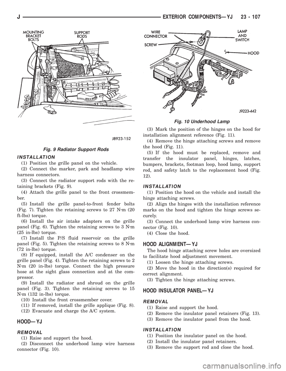
(3) Connect the radiator support rods with the re-
taining brackets (Fig. 9).
(4) Attach the grille panel to the front crossmem-
ber.
(5) Install the grille panel-to-front fender bolts
(Fig. 7). Tighten the retaining screws to 27 Nzm (20
ft-lbs) torque.
(6) Install the air intake adapters on the grille
panel (Fig. 6). Tighten the retaining screws to 3 Nzm
(25 in-lbs) torque.
(7) Install the P/S fluid reservoir on the grille
panel (Fig. 5). Tighten the retaining screws to 8 Nzm
(72 in-lbs) torque.
(8) If equipped, install the A/C condenser on the
grille panel (Fig. 4). Tighten the retaining screws to 2
Nzm (20 in-lbs) torque. Connect the high pressure
hose at the sight glass connection and at the com-
pressor.
(9) Install the radiator and shroud on the grille
panel (Fig. 3). Tighten the retaining screws to 15
Nzm (132 in-lbs) torque.
(10) Install the front crossmember cover.
(11) If removed, install the grille applique (Fig. 8).
(12) Evacuate and charge the A/C system.
HOODÐYJ
REMOVAL
(1) Raise and support the hood.
(2) Disconnect the underhood lamp wire harness
connector (Fig. 10).(3) Mark the position of the hinges on the hood for
installation alignment reference (Fig. 11).
(4) Remove the hinge attaching screws and remove
the hood (Fig. 11).
(5) If the hood must be replaced, remove and
transfer the insulator panel, hinges, latches,
bumpers, brackets, footman loop, hood lamp, support
rod, and safety latch to the replacement hood (Fig.
12).
INSTALLATION
(1) Position the hood on the vehicle and install the
hinge attaching screws.
(2) Align the hinges with the installation reference
marks on the hood and tighten the hinge screws se-
curely.
(3) Connect the underhood lamp wire harness con-
nector (Fig. 10).
(4) Close the hood.
HOOD ALIGNMENTÐYJ
The hood hinge attaching screw holes are oversized
to facilitate hood adjustment movement.
(1) Loosen the hinge attaching screws.
(2) Move the hood in the direction(s) required for
correct alignment.
(3) Tighten the hinge attaching screws.
HOOD INSULATOR PANELÐYJ
REMOVAL
(1) Raise and support the hood.
(2) Remove the insulator panel retainers (Fig. 13).
(3) Remove the insulator panel from the hood.
INSTALLATION
(1) Position the insulator panel on the hood.
(2) Install the insulator panel retainers.
(3) Remove the support rod and close the hood.
Fig. 9 Radiator Support Rods
Fig. 10 Underhood Lamp
JEXTERIOR COMPONENTSÐYJ 23 - 107
Page 2028 of 2158
BATTERY TRAYÐYJ
REMOVAL
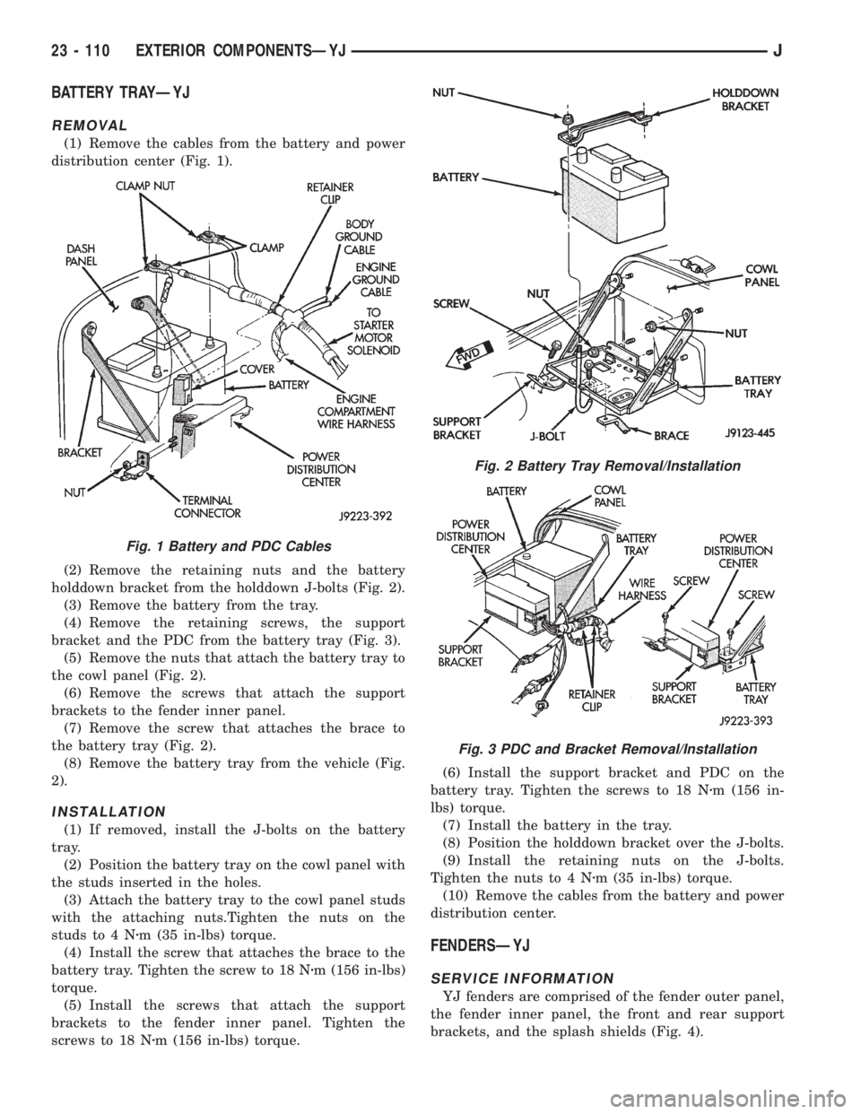
(1) Remove the cables from the battery and power
distribution center (Fig. 1).
(2) Remove the retaining nuts and the battery
holddown bracket from the holddown J-bolts (Fig. 2).
(3) Remove the battery from the tray.
(4) Remove the retaining screws, the support
bracket and the PDC from the battery tray (Fig. 3).
(5) Remove the nuts that attach the battery tray to
the cowl panel (Fig. 2).
(6) Remove the screws that attach the support
brackets to the fender inner panel.
(7) Remove the screw that attaches the brace to
the battery tray (Fig. 2).
(8) Remove the battery tray from the vehicle (Fig.
2).
INSTALLATION
(1) If removed, install the J-bolts on the battery
tray.
(2) Position the battery tray on the cowl panel with
the studs inserted in the holes.
(3) Attach the battery tray to the cowl panel studs
with the attaching nuts.Tighten the nuts on the
studs to 4 Nzm (35 in-lbs) torque.
(4) Install the screw that attaches the brace to the
battery tray. Tighten the screw to 18 Nzm (156 in-lbs)
torque.
(5) Install the screws that attach the support
brackets to the fender inner panel. Tighten the
screws to 18 Nzm (156 in-lbs) torque.(6) Install the support bracket and PDC on the
battery tray. Tighten the screws to 18 Nzm (156 in-
lbs) torque.
(7) Install the battery in the tray.
(8) Position the holddown bracket over the J-bolts.
(9) Install the retaining nuts on the J-bolts.
Tighten the nuts to 4 Nzm (35 in-lbs) torque.
(10) Remove the cables from the battery and power
distribution center.
FENDERSÐYJ
SERVICE INFORMATION
YJ fenders are comprised of the fender outer panel,
the fender inner panel, the front and rear support
brackets, and the splash shields (Fig. 4).
Fig. 1 Battery and PDC Cables
Fig. 2 Battery Tray Removal/Installation
Fig. 3 PDC and Bracket Removal/Installation
23 - 110 EXTERIOR COMPONENTSÐYJJ