1995 JEEP YJ torque
[x] Cancel search: torquePage 2031 of 2158
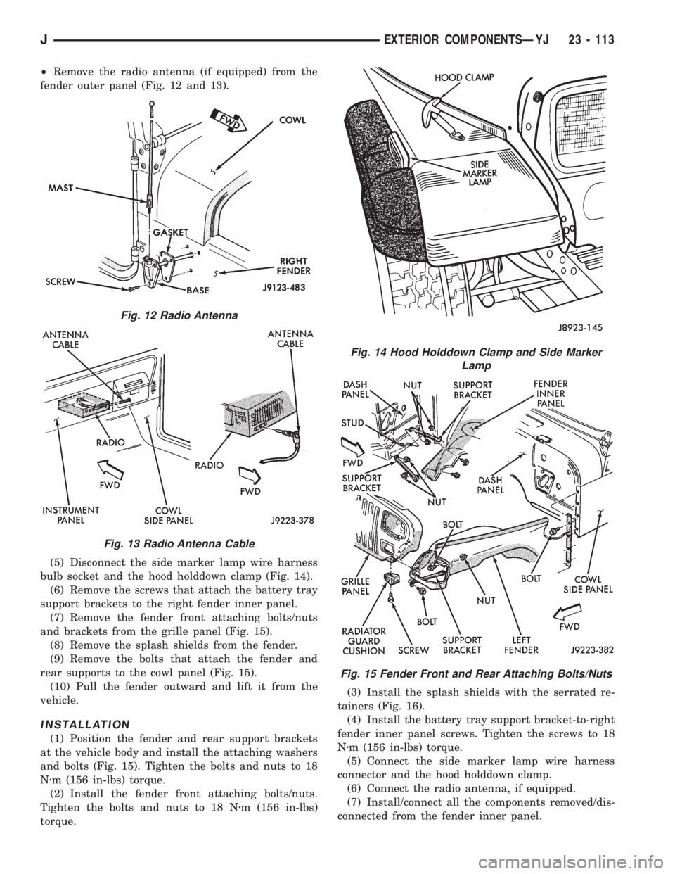
²Remove the radio antenna (if equipped) from the
fender outer panel (Fig. 12 and 13).
(5) Disconnect the side marker lamp wire harness
bulb socket and the hood holddown clamp (Fig. 14).
(6) Remove the screws that attach the battery tray
support brackets to the right fender inner panel.
(7) Remove the fender front attaching bolts/nuts
and brackets from the grille panel (Fig. 15).
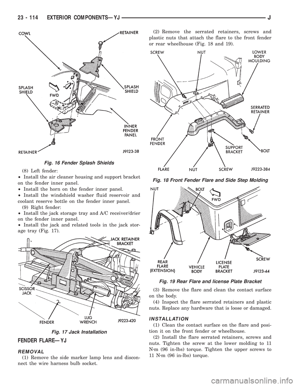
(8) Remove the splash shields from the fender.
(9) Remove the bolts that attach the fender and
rear supports to the cowl panel (Fig. 15).
(10) Pull the fender outward and lift it from the
vehicle.
INSTALLATION
(1) Position the fender and rear support brackets
at the vehicle body and install the attaching washers
and bolts (Fig. 15). Tighten the bolts and nuts to 18
Nzm (156 in-lbs) torque.
(2) Install the fender front attaching bolts/nuts.
Tighten the bolts and nuts to 18 Nzm (156 in-lbs)
torque.(3) Install the splash shields with the serrated re-
tainers (Fig. 16).
(4) Install the battery tray support bracket-to-right
fender inner panel screws. Tighten the screws to 18
Nzm (156 in-lbs) torque.
(5) Connect the side marker lamp wire harness
connector and the hood holddown clamp.
(6) Connect the radio antenna, if equipped.
(7) Install/connect all the components removed/dis-
connected from the fender inner panel.
Fig. 12 Radio Antenna
Fig. 13 Radio Antenna Cable
Fig. 14 Hood Holddown Clamp and Side Marker
Lamp
Fig. 15 Fender Front and Rear Attaching Bolts/Nuts
JEXTERIOR COMPONENTSÐYJ 23 - 113
Page 2032 of 2158
(8) Left fender:
²Install the air cleaner housing and support bracket
on the fender inner panel.
²Install the horn on the fender inner panel.
²Install the windshield washer fluid reservoir and
coolant reserve bottle on the fender inner panel.
(9) Right fender:
²Install the jack storage tray and A/C receiver/drier
on the fender inner panel.
²Install the jack and related tools in the jack stor-
age tray (Fig. 17).
FENDER FLAREÐYJ
REMOVAL
(1) Remove the side marker lamp lens and discon-
nect the wire harness bulb socket.(2) Remove the serrated retainers, screws and
plastic nuts that attach the flare to the front fender
or rear wheelhouse (Fig. 18 and 19).
(3) Remove the flare and clean the contact surface
on the body.
(4) Inspect the flare serrated retainers and plastic
nuts. Replace any hardware that is loose or damaged.
INSTALLATION
(1) Clean the contact surface on the flare and posi-
tion it on the front fender or wheelhouse.
(2) Install the flare serrated retainers, screws and
nuts. Tighten the screw at the lower molding to 11
Nzm (96 in-lbs) torque. Tighten the upper screws to
11 Nzm (96 in-lbs) torque.
Fig. 16 Fender Splash Shields
Fig. 17 Jack Installation
Fig. 18 Front Fender Flare and Side Step Molding
Fig. 19 Rear Flare and license Plate Bracket
23 - 114 EXTERIOR COMPONENTSÐYJJ
Page 2033 of 2158
BODY SIDE STEP MOLDINGÐYJ
REMOVAL/INSTALLATION
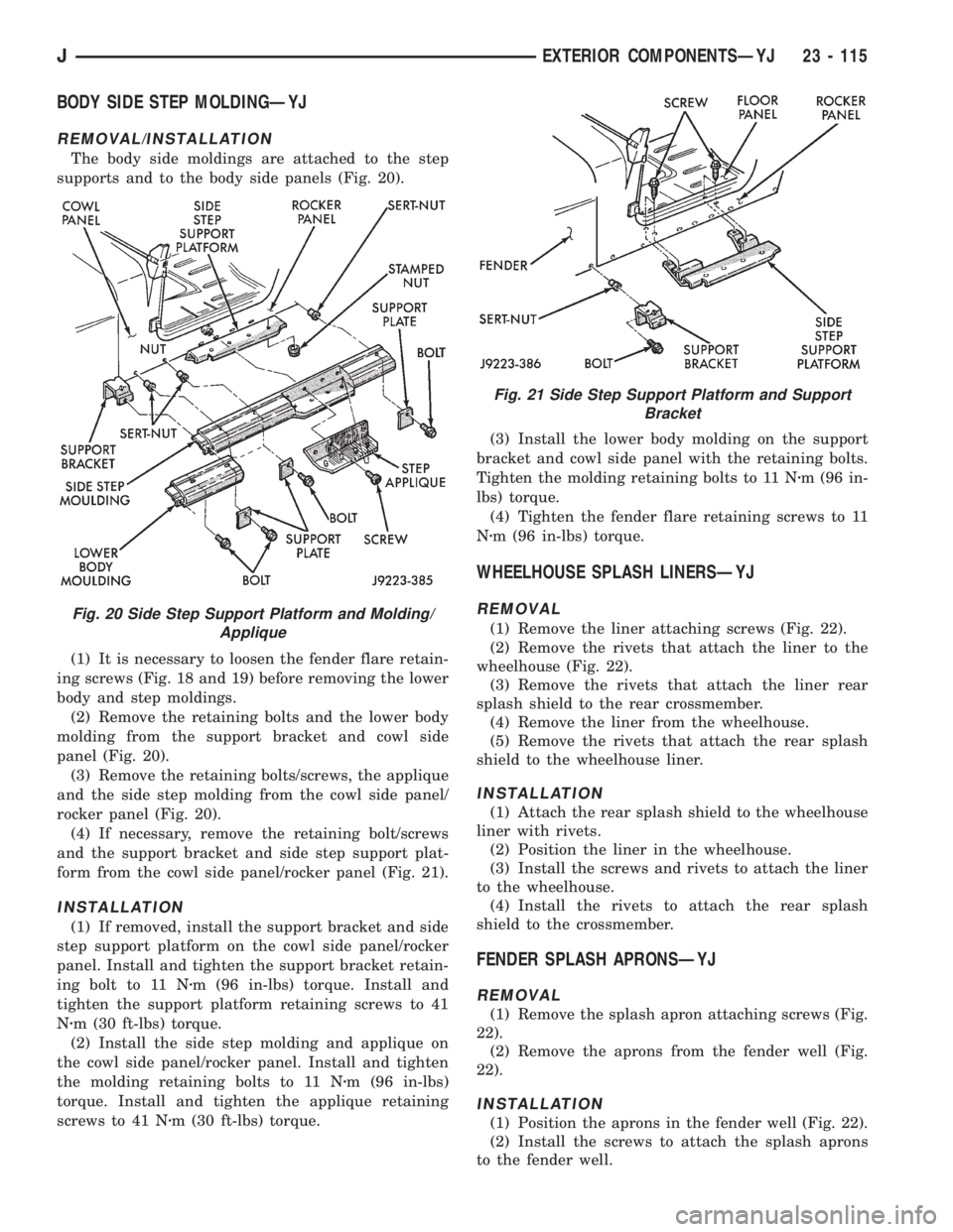
The body side moldings are attached to the step
supports and to the body side panels (Fig. 20).
(1) It is necessary to loosen the fender flare retain-
ing screws (Fig. 18 and 19) before removing the lower
body and step moldings.
(2) Remove the retaining bolts and the lower body
molding from the support bracket and cowl side
panel (Fig. 20).
(3) Remove the retaining bolts/screws, the applique
and the side step molding from the cowl side panel/
rocker panel (Fig. 20).
(4) If necessary, remove the retaining bolt/screws
and the support bracket and side step support plat-
form from the cowl side panel/rocker panel (Fig. 21).
INSTALLATION
(1) If removed, install the support bracket and side
step support platform on the cowl side panel/rocker
panel. Install and tighten the support bracket retain-
ing bolt to 11 Nzm (96 in-lbs) torque. Install and
tighten the support platform retaining screws to 41
Nzm (30 ft-lbs) torque.
(2) Install the side step molding and applique on
the cowl side panel/rocker panel. Install and tighten
the molding retaining bolts to 11 Nzm (96 in-lbs)
torque. Install and tighten the applique retaining
screws to 41 Nzm (30 ft-lbs) torque.(3) Install the lower body molding on the support
bracket and cowl side panel with the retaining bolts.
Tighten the molding retaining bolts to 11 Nzm (96 in-
lbs) torque.
(4) Tighten the fender flare retaining screws to 11
Nzm (96 in-lbs) torque.
WHEELHOUSE SPLASH LINERSÐYJ
REMOVAL
(1) Remove the liner attaching screws (Fig. 22).
(2) Remove the rivets that attach the liner to the
wheelhouse (Fig. 22).
(3) Remove the rivets that attach the liner rear
splash shield to the rear crossmember.
(4) Remove the liner from the wheelhouse.
(5) Remove the rivets that attach the rear splash
shield to the wheelhouse liner.
INSTALLATION
(1) Attach the rear splash shield to the wheelhouse
liner with rivets.
(2) Position the liner in the wheelhouse.
(3) Install the screws and rivets to attach the liner
to the wheelhouse.
(4) Install the rivets to attach the rear splash
shield to the crossmember.
FENDER SPLASH APRONSÐYJ
REMOVAL
(1) Remove the splash apron attaching screws (Fig.
22).
(2) Remove the aprons from the fender well (Fig.
22).
INSTALLATION
(1) Position the aprons in the fender well (Fig. 22).
(2) Install the screws to attach the splash aprons
to the fender well.
Fig. 20 Side Step Support Platform and Molding/
Applique
Fig. 21 Side Step Support Platform and Support
Bracket
JEXTERIOR COMPONENTSÐYJ 23 - 115
Page 2039 of 2158
(3) Position the replacement nameplate on the
panel and apply inward force to seat it.
FUEL FILLER PROTECTOR/NOZZLEÐYJ
REMOVAL
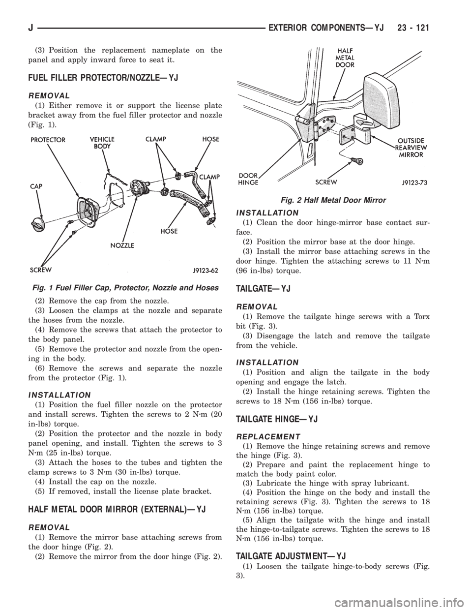
(1) Either remove it or support the license plate
bracket away from the fuel filler protector and nozzle
(Fig. 1).
(2) Remove the cap from the nozzle.
(3) Loosen the clamps at the nozzle and separate
the hoses from the nozzle.
(4) Remove the screws that attach the protector to
the body panel.
(5) Remove the protector and nozzle from the open-
ing in the body.
(6) Remove the screws and separate the nozzle
from the protector (Fig. 1).
INSTALLATION
(1) Position the fuel filler nozzle on the protector
and install screws. Tighten the screws to 2 Nzm (20
in-lbs) torque.
(2) Position the protector and the nozzle in body
panel opening, and install. Tighten the screws to 3
Nzm (25 in-lbs) torque.
(3) Attach the hoses to the tubes and tighten the
clamp screws to 3 Nzm (30 in-lbs) torque.
(4) Install the cap on the nozzle.
(5) If removed, install the license plate bracket.
HALF METAL DOOR MIRROR (EXTERNAL)ÐYJ
REMOVAL
(1) Remove the mirror base attaching screws from
the door hinge (Fig. 2).
(2) Remove the mirror from the door hinge (Fig. 2).
INSTALLATION
(1) Clean the door hinge-mirror base contact sur-
face.
(2) Position the mirror base at the door hinge.
(3) Install the mirror base attaching screws in the
door hinge. Tighten the attaching screws to 11 Nzm
(96 in-lbs) torque.
TAILGATEÐYJ
REMOVAL
(1) Remove the tailgate hinge screws with a Torx
bit (Fig. 3).
(3) Disengage the latch and remove the tailgate
from the vehicle.
INSTALLATION
(1) Position and align the tailgate in the body
opening and engage the latch.
(2) Install the hinge retaining screws. Tighten the
screws to 18 Nzm (156 in-lbs) torque.
TAILGATE HINGEÐYJ
REPLACEMENT
(1) Remove the hinge retaining screws and remove
the hinge (Fig. 3).
(2) Prepare and paint the replacement hinge to
match the body paint color.
(3) Lubricate the hinge with spray lubricant.
(4) Position the hinge on the body and install the
retaining screws (Fig. 3). Tighten the screws to 18
Nzm (156 in-lbs) torque.
(5) Align the tailgate with the hinge and install
the hinge-to-tailgate screws. Tighten the screws to 18
Nzm (156 in-lbs) torque.
TAILGATE ADJUSTMENTÐYJ
(1) Loosen the tailgate hinge-to-body screws (Fig.
3).
Fig. 1 Fuel Filler Cap, Protector, Nozzle and Hoses
Fig. 2 Half Metal Door Mirror
JEXTERIOR COMPONENTSÐYJ 23 - 121
Page 2040 of 2158
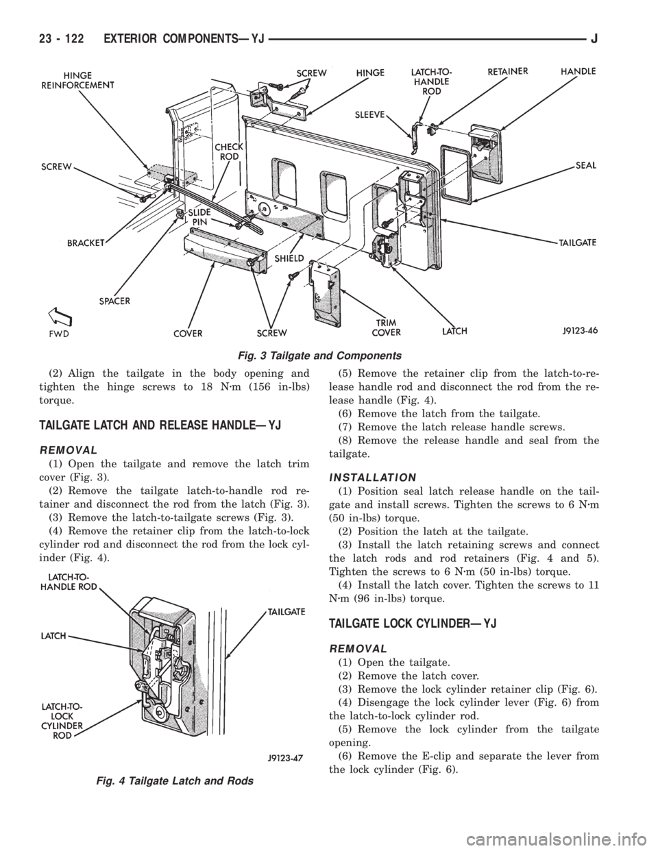
(2) Align the tailgate in the body opening and
tighten the hinge screws to 18 Nzm (156 in-lbs)
torque.
TAILGATE LATCH AND RELEASE HANDLEÐYJ
REMOVAL
(1) Open the tailgate and remove the latch trim
cover (Fig. 3).
(2) Remove the tailgate latch-to-handle rod re-
tainer and disconnect the rod from the latch (Fig. 3).
(3) Remove the latch-to-tailgate screws (Fig. 3).
(4) Remove the retainer clip from the latch-to-lock
cylinder rod and disconnect the rod from the lock cyl-
inder (Fig. 4).(5) Remove the retainer clip from the latch-to-re-
lease handle rod and disconnect the rod from the re-
lease handle (Fig. 4).
(6) Remove the latch from the tailgate.
(7) Remove the latch release handle screws.
(8) Remove the release handle and seal from the
tailgate.
INSTALLATION
(1) Position seal latch release handle on the tail-
gate and install screws. Tighten the screws to 6 Nzm
(50 in-lbs) torque.
(2) Position the latch at the tailgate.
(3) Install the latch retaining screws and connect
the latch rods and rod retainers (Fig. 4 and 5).
Tighten the screws to 6 Nzm (50 in-lbs) torque.
(4) Install the latch cover. Tighten the screws to 11
Nzm (96 in-lbs) torque.
TAILGATE LOCK CYLINDERÐYJ
REMOVAL
(1) Open the tailgate.
(2) Remove the latch cover.
(3) Remove the lock cylinder retainer clip (Fig. 6).
(4) Disengage the lock cylinder lever (Fig. 6) from
the latch-to-lock cylinder rod.
(5) Remove the lock cylinder from the tailgate
opening.
(6) Remove the E-clip and separate the lever from
the lock cylinder (Fig. 6).
Fig. 3 Tailgate and Components
Fig. 4 Tailgate Latch and Rods
23 - 122 EXTERIOR COMPONENTSÐYJJ
Page 2041 of 2158
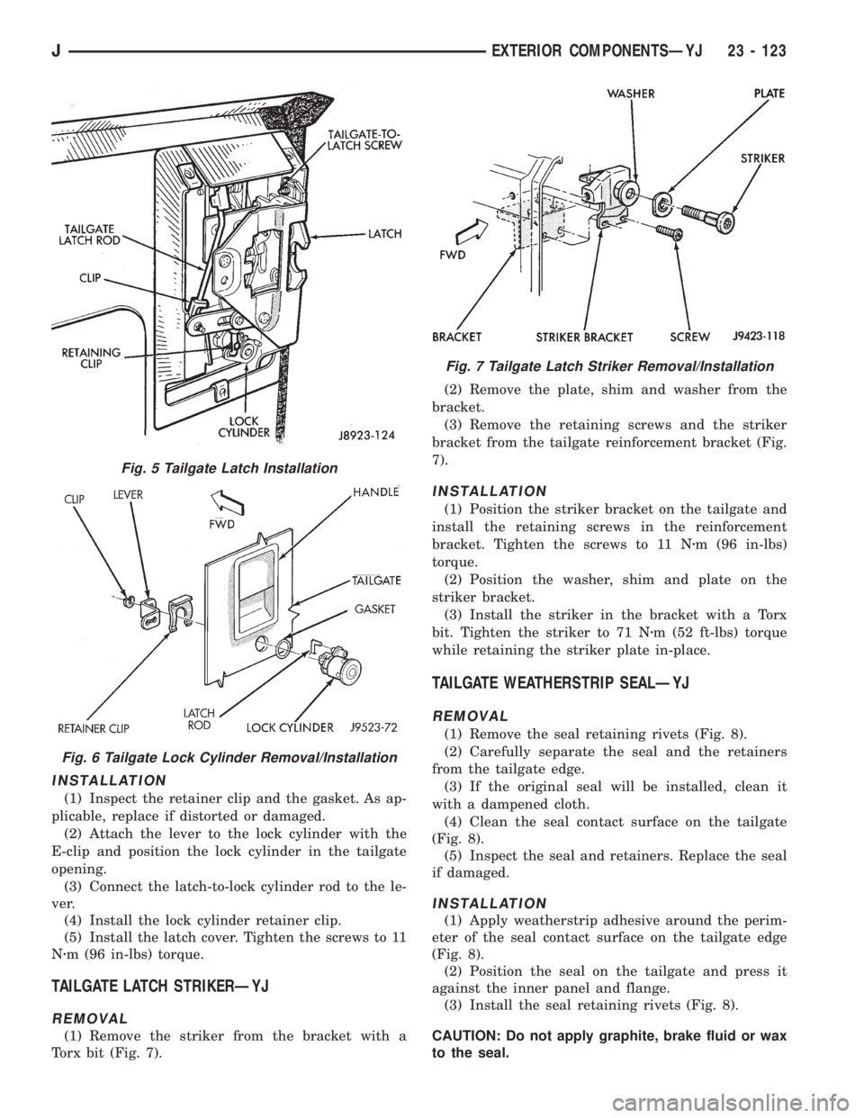
INSTALLATION
(1) Inspect the retainer clip and the gasket. As ap-
plicable, replace if distorted or damaged.
(2) Attach the lever to the lock cylinder with the
E-clip and position the lock cylinder in the tailgate
opening.
(3) Connect the latch-to-lock cylinder rod to the le-
ver.
(4) Install the lock cylinder retainer clip.
(5) Install the latch cover. Tighten the screws to 11
Nzm (96 in-lbs) torque.
TAILGATE LATCH STRIKERÐYJ
REMOVAL
(1) Remove the striker from the bracket with a
Torx bit (Fig. 7).(2) Remove the plate, shim and washer from the
bracket.
(3) Remove the retaining screws and the striker
bracket from the tailgate reinforcement bracket (Fig.
7).
INSTALLATION
(1) Position the striker bracket on the tailgate and
install the retaining screws in the reinforcement
bracket. Tighten the screws to 11 Nzm (96 in-lbs)
torque.
(2) Position the washer, shim and plate on the
striker bracket.
(3) Install the striker in the bracket with a Torx
bit. Tighten the striker to 71 Nzm (52 ft-lbs) torque
while retaining the striker plate in-place.
TAILGATE WEATHERSTRIP SEALÐYJ
REMOVAL
(1) Remove the seal retaining rivets (Fig. 8).
(2) Carefully separate the seal and the retainers
from the tailgate edge.
(3) If the original seal will be installed, clean it
with a dampened cloth.
(4) Clean the seal contact surface on the tailgate
(Fig. 8).
(5) Inspect the seal and retainers. Replace the seal
if damaged.
INSTALLATION
(1) Apply weatherstrip adhesive around the perim-
eter of the seal contact surface on the tailgate edge
(Fig. 8).
(2) Position the seal on the tailgate and press it
against the inner panel and flange.
(3) Install the seal retaining rivets (Fig. 8).
CAUTION: Do not apply graphite, brake fluid or wax
to the seal.
Fig. 5 Tailgate Latch Installation
Fig. 6 Tailgate Lock Cylinder Removal/Installation
Fig. 7 Tailgate Latch Striker Removal/Installation
JEXTERIOR COMPONENTSÐYJ 23 - 123
Page 2043 of 2158
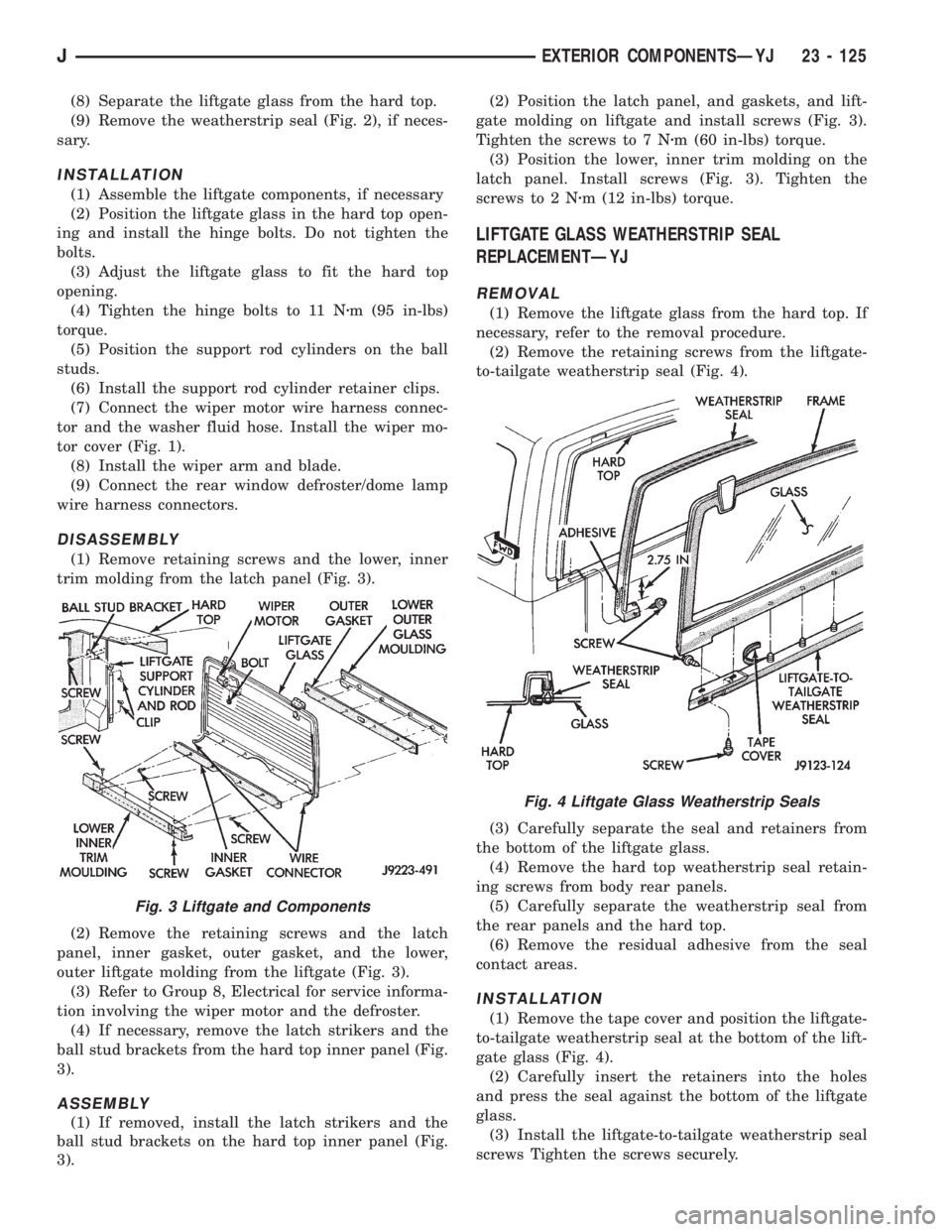
(8) Separate the liftgate glass from the hard top.
(9) Remove the weatherstrip seal (Fig. 2), if neces-
sary.
INSTALLATION
(1) Assemble the liftgate components, if necessary
(2) Position the liftgate glass in the hard top open-
ing and install the hinge bolts. Do not tighten the
bolts.
(3) Adjust the liftgate glass to fit the hard top
opening.
(4) Tighten the hinge bolts to 11 Nzm (95 in-lbs)
torque.
(5) Position the support rod cylinders on the ball
studs.
(6) Install the support rod cylinder retainer clips.
(7) Connect the wiper motor wire harness connec-
tor and the washer fluid hose. Install the wiper mo-
tor cover (Fig. 1).
(8) Install the wiper arm and blade.
(9) Connect the rear window defroster/dome lamp
wire harness connectors.
DISASSEMBLY
(1) Remove retaining screws and the lower, inner
trim molding from the latch panel (Fig. 3).
(2) Remove the retaining screws and the latch
panel, inner gasket, outer gasket, and the lower,
outer liftgate molding from the liftgate (Fig. 3).
(3) Refer to Group 8, Electrical for service informa-
tion involving the wiper motor and the defroster.
(4) If necessary, remove the latch strikers and the
ball stud brackets from the hard top inner panel (Fig.
3).
ASSEMBLY
(1) If removed, install the latch strikers and the
ball stud brackets on the hard top inner panel (Fig.
3).(2) Position the latch panel, and gaskets, and lift-
gate molding on liftgate and install screws (Fig. 3).
Tighten the screws to 7 Nzm (60 in-lbs) torque.
(3) Position the lower, inner trim molding on the
latch panel. Install screws (Fig. 3). Tighten the
screws to 2 Nzm (12 in-lbs) torque.
LIFTGATE GLASS WEATHERSTRIP SEAL
REPLACEMENTÐYJ
REMOVAL
(1) Remove the liftgate glass from the hard top. If
necessary, refer to the removal procedure.
(2) Remove the retaining screws from the liftgate-
to-tailgate weatherstrip seal (Fig. 4).
(3) Carefully separate the seal and retainers from
the bottom of the liftgate glass.
(4) Remove the hard top weatherstrip seal retain-
ing screws from body rear panels.
(5) Carefully separate the weatherstrip seal from
the rear panels and the hard top.
(6) Remove the residual adhesive from the seal
contact areas.
INSTALLATION
(1) Remove the tape cover and position the liftgate-
to-tailgate weatherstrip seal at the bottom of the lift-
gate glass (Fig. 4).
(2) Carefully insert the retainers into the holes
and press the seal against the bottom of the liftgate
glass.
(3) Install the liftgate-to-tailgate weatherstrip seal
screws Tighten the screws securely.
Fig. 3 Liftgate and Components
Fig. 4 Liftgate Glass Weatherstrip Seals
JEXTERIOR COMPONENTSÐYJ 23 - 125
Page 2050 of 2158
channel. Close the rear window curtain zippers and
attach the side snap-on retainers.
(16) Attach all the top cover snap-on retainers to
the upper side retainers located above both doors. As
necessary, slide the mating half of the snap-on re-
tainers so that they will align with the snap-on re-
tainers on the top cover. Tuck the edge of the top
cover inside the side retainer.
(17) Install the door windows by inserting the re-
tainers into the door grommets. Attach the snap-on
retainers located along the bottom edge of the win-
dow to the door retainer.
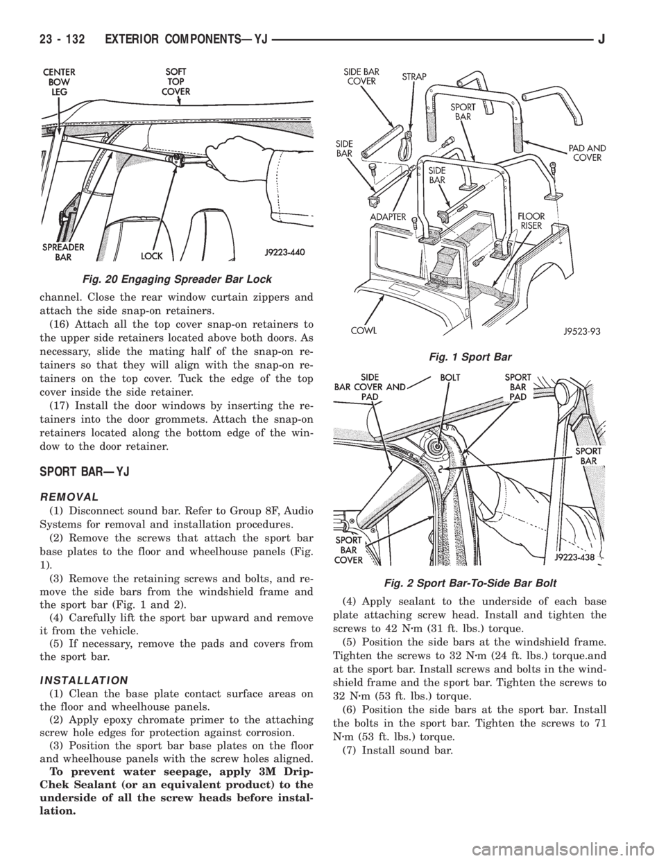
SPORT BARÐYJ
REMOVAL
(1) Disconnect sound bar. Refer to Group 8F, Audio
Systems for removal and installation procedures.
(2) Remove the screws that attach the sport bar
base plates to the floor and wheelhouse panels (Fig.
1).
(3) Remove the retaining screws and bolts, and re-
move the side bars from the windshield frame and
the sport bar (Fig. 1 and 2).
(4) Carefully lift the sport bar upward and remove
it from the vehicle.
(5) If necessary, remove the pads and covers from
the sport bar.
INSTALLATION
(1) Clean the base plate contact surface areas on
the floor and wheelhouse panels.
(2) Apply epoxy chromate primer to the attaching
screw hole edges for protection against corrosion.
(3) Position the sport bar base plates on the floor
and wheelhouse panels with the screw holes aligned.
To prevent water seepage, apply 3M Drip-
Chek Sealant (or an equivalent product) to the
underside of all the screw heads before instal-
lation.(4) Apply sealant to the underside of each base
plate attaching screw head. Install and tighten the
screws to 42 Nzm (31 ft. lbs.) torque.
(5) Position the side bars at the windshield frame.
Tighten the screws to 32 Nzm (24 ft. lbs.) torque.and
at the sport bar. Install screws and bolts in the wind-
shield frame and the sport bar. Tighten the screws to
32 Nzm (53 ft. lbs.) torque.
(6) Position the side bars at the sport bar. Install
the bolts in the sport bar. Tighten the screws to 71
Nzm (53 ft. lbs.) torque.
(7) Install sound bar.
Fig. 20 Engaging Spreader Bar Lock
Fig. 1 Sport Bar
Fig. 2 Sport Bar-To-Side Bar Bolt
23 - 132 EXTERIOR COMPONENTSÐYJJ