1995 JEEP YJ torque
[x] Cancel search: torquePage 2072 of 2158
If the floor brackets are not to be replaced, it is not
necessary to remove the rear screws to remove the
rear seat. Follow step (3) for seat disengagement.
REMOVAL
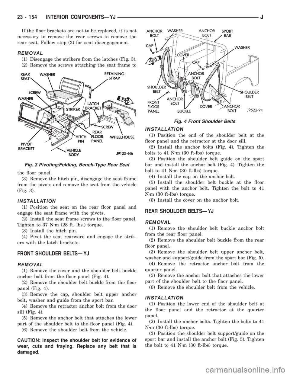
(1) Disengage the strikers from the latches (Fig. 3).
(2) Remove the screws attaching the seat frame to
the floor panel.
(3) Remove the hitch pin, disengage the seat frame
from the pivots and remove the seat from the vehicle
(Fig. 3).
INSTALLATION
(1) Position the seat on the rear floor panel and
engage the seat frame with the pivots.
(2) Install the seat frame screws to the floor panel.
Tighten to 37 Nzm (28 ft. lbs.) torque.
(3) Install the hitch pin.
(4) Pivot the seat rearward and engage the strik-
ers with the latch brackets.
FRONT SHOULDER BELTSÐYJ
REMOVAL
(1) Remove the cover and the shoulder belt buckle
anchor bolt from the floor panel (Fig. 4).
(2) Remove the shoulder belt buckle from the floor
panel (Fig. 4).
(3) Remove the cap, shoulder belt upper anchor
bolt, washer and guide from the sport bar.
(4) Remove the retractor anchor bolt from the door
sill (Fig. 4).
(5) Remove the anchor bolt that attaches the lower
part of the shoulder belt to the floor panel (Fig. 4).
(6) Remove the shoulder belt from the vehicle.
CAUTION: Inspect the shoulder belt for evidence of
wear, cuts and fraying. Replace any belt that is
damaged.
INSTALLATION
(1) Position the end of the shoulder belt at the
floor panel and the retractor at the door sill.
(2) Install the anchor bolts (Fig. 4). Tighten the
bolts to 41 Nzm (30 ft-lbs) torque.
(3) Position the shoulder belt guide on the sport
bar and install the anchor bolt (Fig. 4). Tighten the
bolt to 41 Nzm (30 ft-lbs) torque.
(4) Install the cap on the anchor bolt.
(5) Install the shoulder belt buckle at the floor
panel with the anchor bolt. Tighten the bolt to 41
Nzm (30 ft-lbs) torque.
(6) Install the cover on the anchor bolt.
REAR SHOULDER BELTSÐYJ
REMOVAL
(1) Remove the shoulder belt buckle anchor bolt
from the rear floor panel.
(2) Remove the shoulder belt buckle from the rear
floor panel.
(3) Remove the shoulder belt upper anchor bolt,
washer and support/guide from the sport bar (Fig. 5).
(4) Remove the retractor anchor bolt from the
quarter panel.
(5) Remove the anchor bolt that attaches the lower
part of the shoulder belt to the floor panel.
(6) Remove the shoulder belt from the vehicle.
INSTALLATION
(1) Position the lower end of the shoulder belt at
the floor panel and the retractor at the quarter
panel.
(2) Install the anchor bolts. Tighten the bolts to 41
Nzm (30 ft-lbs) torque.
(3) Position the shoulder belt support/guide on the
sport bar and install the anchor bolt (Fig. 5). Tighten
the bolt to 41 Nzm (30 ft-lbs) torque.
Fig. 3 Pivoting/Folding, Bench-Type Rear Seat
Fig. 4 Front Shoulder Belts
23 - 154 INTERIOR COMPONENTSÐYJJ
Page 2073 of 2158
(4) Install the shoulder belt buckle at the floor
panel with the anchor bolt. Tighten the bolt to 41
Nzm (30 ft-lbs) torque.
SUNVISORSÐYJ
REMOVAL
(1) Remove the screws that attach the sunvisor
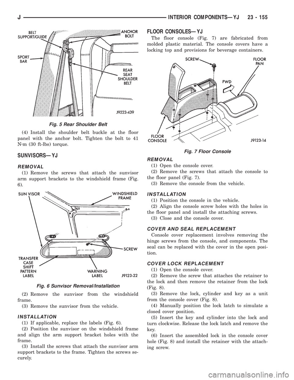
arm support brackets to the windshield frame (Fig.
6).
(2) Remove the sunvisor from the windshield
frame.
(3) Remove the sunvisor from the vehicle.
INSTALLATION
(1) If applicable, replace the labels (Fig. 6).
(2) Position the sunvisor on the windshield frame
and align the arm support bracket holes with the
frame.
(3) Install the screws that attach the sunvisor arm
support brackets to the frame. Tighten the screws se-
curely.
FLOOR CONSOLESÐYJ
The floor console (Fig. 7) are fabricated from
molded plastic material. The console covers have a
locking top and provisions for beverage containers.
REMOVAL
(1) Open the console cover.
(2) Remove the screws that attach the console to
the floor panel (Fig. 7).
(3) Remove the console from the vehicle.
INSTALLATION
(1) Position the console in the vehicle.
(2) Align the console screw holes with the holes in
the floor panel and install the attaching screws.
(3) Close and the console cover.
COVER AND SEAL REPLACEMENT
Console cover replacement involves removing the
hinge screws from the console, and components. The
seal can be replaced with the cover in the open posi-
tion.
COVER LOCK REPLACEMENT
(1) Open the console cover.
(2) Remove the screw that attaches the retainer to
the lock and then remove the retainer from the lock
(Fig. 8).
(3) Remove the lock, cylinder and key as a unit
from the console cover (Fig. 8).
(4) Manually position the lock latch to simulate a
closed cover position.
(5) Insert the key and cylinder into the lock and
turn clockwise. Release the lock latch and remove the
key.
(6) Insert the assembled lock in the console cover
hole (Fig. 8) and install the retainer with the attach-
ing screw.
Fig. 5 Rear Shoulder Belt
Fig. 6 Sunvisor Removal/Installation
Fig. 7 Floor Console
JINTERIOR COMPONENTSÐYJ 23 - 155
Page 2079 of 2158
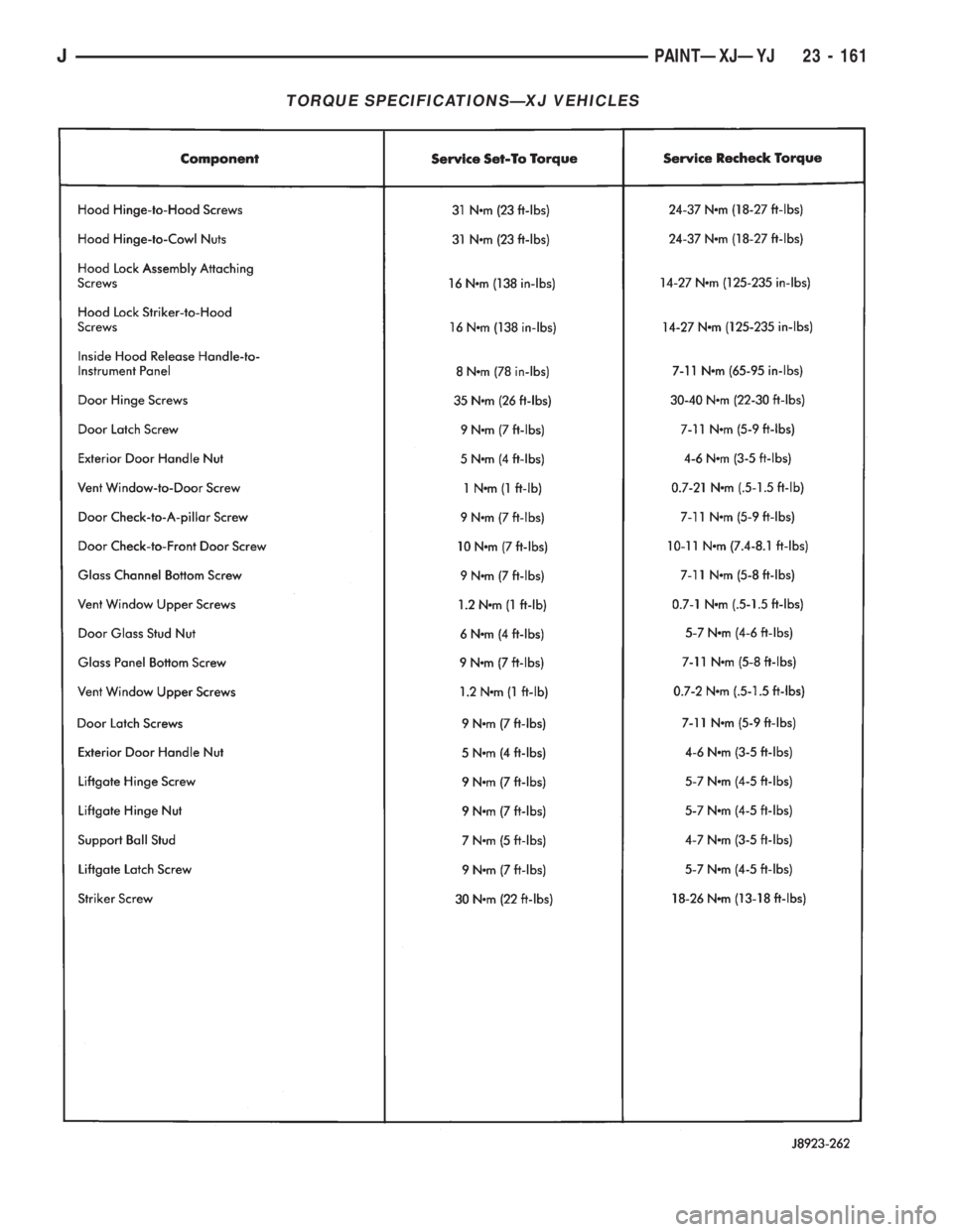
TORQUE SPECIFICATIONSÐXJ VEHICLES
JPAINTÐXJÐYJ 23 - 161
Page 2080 of 2158
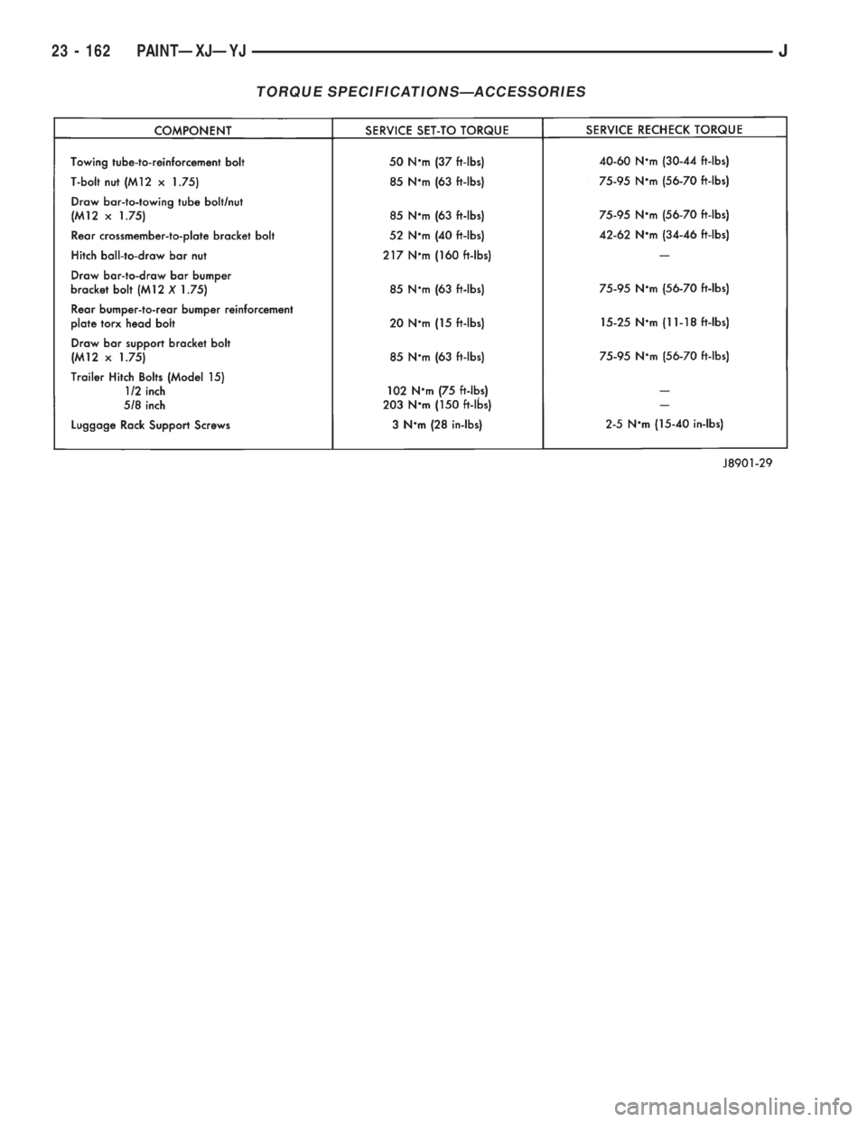
TORQUE SPECIFICATIONSÐACCESSORIES
23 - 162 PAINTÐXJÐYJJ
Page 2081 of 2158
HEATING AND AIR CONDITIONING
CONTENTS
page page
COMPONENT SERVICEÐXJ VEHICLES...... 23
COMPONENT SERVICEÐYJ VEHICLES...... 32
COMPRESSOR SERVICE.................. 19
GENERAL INFORMATION.................. 1
HEATING AND AIR CONDITIONING TEST
PROCEDURES......................... 15REFRIGERANT SERVICE AND PERFORMANCE
TEST................................ 11
TORQUE SPECIFICATIONS................ 37
WARNINGS, CAUTIONS AND SERVICE
PRECAUTIONS......................... 9
GENERAL INFORMATION
INDEX
page page
A/C Components.......................... 4
Heater and A/C Operation.................... 1
Manifold Gauge Set........................ 7Refrigerant............................... 7
Refrigerant Equipment...................... 7
HEATER AND A/C OPERATION
HEATERÐXJ
A blend-air heating system is used in XJ vehicles.
The temperature of heated air is controlled by regu-
lating the quantity of air flow through the heater
core. This is accomplished by blending outside air
with heated air from the heater core to obtain the de-
sired discharge temperature. A temperature control
lever on the heater control determines air flow
through the heater core. The lever uses a cable to op-erate the blend-air door. This door controls air flow
through the core. Vacuum motors are used to actuate
and position the remaining door in the system.
On left hand drive (LHD) XJ vehicles a water valve
controls coolant flow to the heater core. The valve is
vacuum operated. When vacuum is applied, the valve
opens and coolant is directed through the heater core
and back to the engine. When the water valve is
closed (no vacuum applied) coolant flow bypasses the
heater core back to the engine.
JHEATING AND AIR CONDITIONING 24 - 1
Page 2089 of 2158
WARNINGS, CAUTIONS AND SERVICE PRECAUTIONS
WARNINGS
WARNING: THE AIR CONDITIONING SYSTEM CON-
TAINS REFRIGERANT UNDER HIGH PRESSURE.
SEVERE PERSONAL INJURY MAY RESULT FROM
IMPROPER SERVICE PROCEDURES. REPAIRS
SHOULD ONLY BE PERFORMED BY QUALIFIED
SERVICE PERSONNEL.
WARNING: AVOID BREATHING A/C REFRIGERANT
AND LUBRICANT VAPOR OR MIST. EXPOSURE MAY
IRRITATE EYES, NOSE AND/OR THROAT. WEAR
EYE PROTECTION WHEN SERVICING THE AIR
CONDITIONING REFRIGERANT SYSTEM. SERIOUS
EYE INJURY CAN RESULT FROM EYE CONTACT
WITH REFRIGERANT. IF EYE CONTACT IS MADE,
SEEK MEDICAL ATTENTION IMMEDIATELY.
WARNING: DO NOT EXPOSE REFRIGERANT TO
OPEN FLAME. POISONOUS GAS IS CREATED
WHEN REFRIGERANT IS BURNED. AN ELEC-
TRONIC TYPE LEAK DETECTOR IS RECOM-
MENDED.
WARNING: IF ACCIDENTAL SYSTEM DISCHARGE
OCCURS, VENTILATE THE WORK AREA BEFORE
RESUMING SERVICE. LARGE AMOUNTS OF RE-
FRIGERANT RELEASED IN A CLOSED WORK AREA
WILL DISPLACE THE OXYGEN AND CAUSE SUFFO-
CATION.
WARNING: THE EVAPORATION RATE OF (R-134A)
REFRIGERANT AT AVERAGE TEMPERATURE AND
ALTITUDE IS EXTREMELY HIGH. AS A RESULT,
ANYTHING THAT COMES IN CONTACT WITH THE
REFRIGERANT WILL FREEZE. ALWAYS PROTECT
SKIN OR DELICATE OBJECTS FROM DIRECT CON-
TACT WITH REFRIGERANT.
WARNING: R-134A SERVICE EQUIPMENT OR VEHI-
CLE A/C SYSTEM SHOULD NOT BE PRESSURE
TESTED OR LEAK TESTED WITH COMPRESSED
AIR. SOME MIXTURES OF AIR AND R-134A HAVE
BEEN SHOWN TO BE COMBUSTIBLE AT ELEVATED
PRESSURES. THESE MIXTURES ARE POTENTIALLY
DANGEROUS AND MAY RESULT IN FIRE OR EX-
PLOSION CAUSING INJURY OR PROPERTY DAM-
AGE.
CAUTIONS
CAUTION: Liquid refrigerant is corrosive to metal
surfaces. Follow the operating instructions supplied
with equipment being used.
CAUTION: DO NOT use R-12 equipment or parts on
the R-134a system. Damage to the system will re-
sult.
CAUTION: Never add R-12 to a system designed to
use R-134a. Damage to the system will result.
CAUTION: R-12 compressor oil can not be mixed
with the R-134a compressor oil. They ARE NOT
compatible.
CAUTION: Do not over charge refrigerant system.
This will cause excessive compressor head pres-
sure and can cause noise and system failure.
SERVICE PRECAUTIONS
Recover the refrigerant before opening any fitting
or connection. Open fittings with caution even after
the system has been discharged. Never open or
loosen a connection before recovering the refrigerant.
The A/C system must always be evacuated before
charging.
DO NOT open the refrigerant system or uncap a
replacement component until you are ready to service
the system. This will prevent contamination in the
system.
Before disconnecting a component clean the outside
of the fittings thoroughly to prevent contamination
entering the system.
Immediately after disconnecting a component from
the system, seal the open fittings with a cap or plug.
Before connecting an open fitting always install a
new seal/gasket. Coat the fitting and seal with clean
refrigerant oil before connecting.
When installing a refrigerant line avoid sharp
bends. Position the lines away from the exhaust or
any sharp edges which may chafe the line.
Tighten fittings only to the specified torque. The
aluminum fittings used in the A/C system will not
tolerate over tightening.
When disconnecting a fitting use a wrench on both
halves of the fitting. This will prevent twisting of the
refrigerant lines or tubes.
Refrigerant oil absorbs moisture from the atmo-
sphere if left uncapped. DO NOT open a container of
JHEATING AND AIR CONDITIONING 24 - 9
Page 2099 of 2158
COMPRESSOR SERVICE
DESCRIPTION
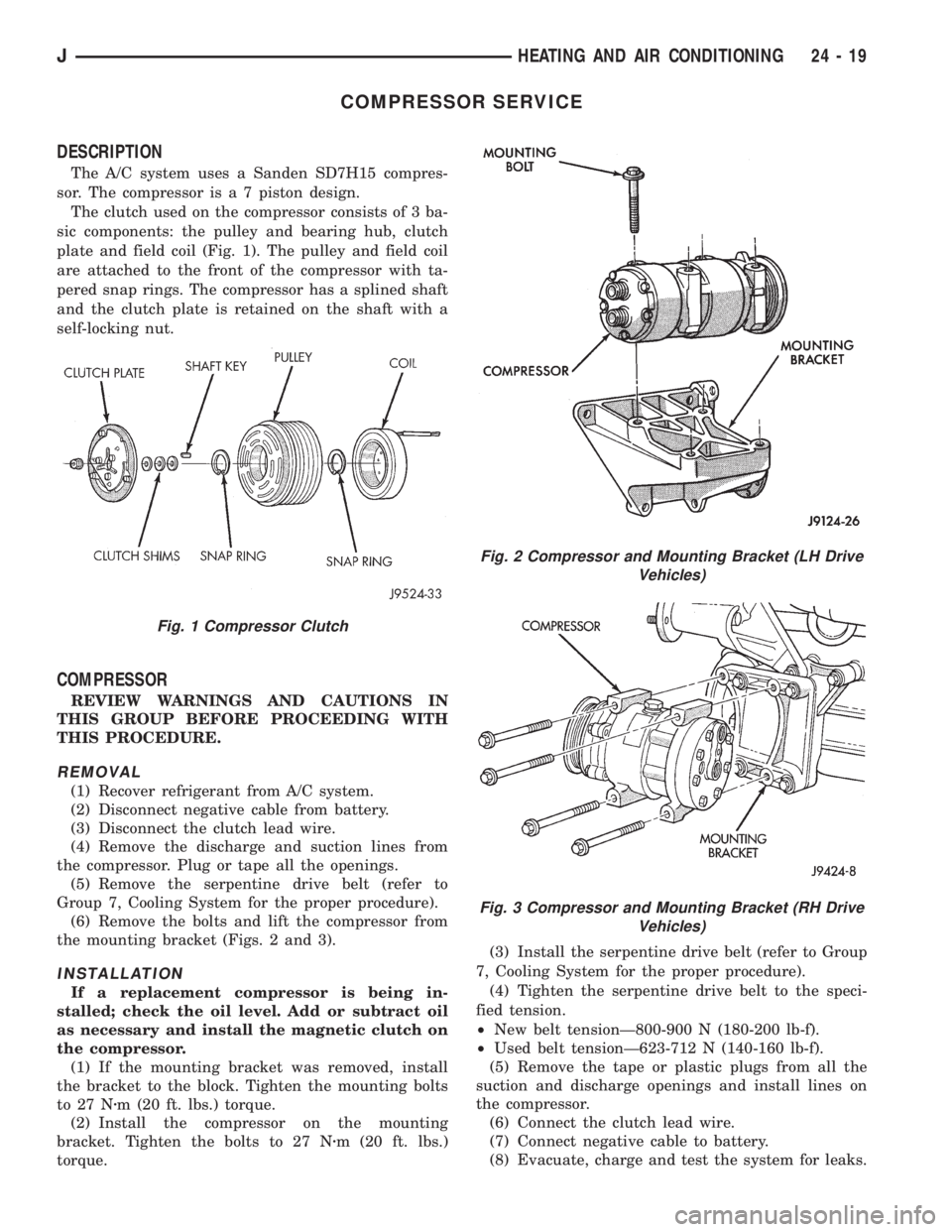
The A/C system uses a Sanden SD7H15 compres-
sor. The compressor is a 7 piston design.
The clutch used on the compressor consists of 3 ba-
sic components: the pulley and bearing hub, clutch
plate and field coil (Fig. 1). The pulley and field coil
are attached to the front of the compressor with ta-
pered snap rings. The compressor has a splined shaft
and the clutch plate is retained on the shaft with a
self-locking nut.
COMPRESSOR
REVIEW WARNINGS AND CAUTIONS IN
THIS GROUP BEFORE PROCEEDING WITH
THIS PROCEDURE.
REMOVAL
(1) Recover refrigerant from A/C system.
(2) Disconnect negative cable from battery.
(3) Disconnect the clutch lead wire.
(4) Remove the discharge and suction lines from
the compressor. Plug or tape all the openings.
(5) Remove the serpentine drive belt (refer to
Group 7, Cooling System for the proper procedure).
(6) Remove the bolts and lift the compressor from
the mounting bracket (Figs. 2 and 3).
INSTALLATION
If a replacement compressor is being in-
stalled; check the oil level. Add or subtract oil
as necessary and install the magnetic clutch on
the compressor.
(1) If the mounting bracket was removed, install
the bracket to the block. Tighten the mounting bolts
to 27 Nzm (20 ft. lbs.) torque.
(2) Install the compressor on the mounting
bracket. Tighten the bolts to 27 Nzm (20 ft. lbs.)
torque.(3) Install the serpentine drive belt (refer to Group
7, Cooling System for the proper procedure).
(4) Tighten the serpentine drive belt to the speci-
fied tension.
²New belt tensionÐ800-900 N (180-200 lb-f).
²Used belt tensionÐ623-712 N (140-160 lb-f).
(5) Remove the tape or plastic plugs from all the
suction and discharge openings and install lines on
the compressor.
(6) Connect the clutch lead wire.
(7) Connect negative cable to battery.
(8) Evacuate, charge and test the system for leaks.
Fig. 1 Compressor Clutch
Fig. 2 Compressor and Mounting Bracket (LH Drive
Vehicles)
Fig. 3 Compressor and Mounting Bracket (RH Drive
Vehicles)
JHEATING AND AIR CONDITIONING 24 - 19
Page 2101 of 2158
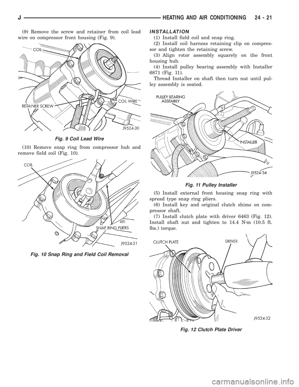
(9) Remove the screw and retainer from coil lead
wire on compressor front housing (Fig. 9).
(10) Remove snap ring from compressor hub and
remove field coil (Fig. 10).INSTALLATION
(1) Install field coil and snap ring.
(2) Install coil harness retaining clip on compres-
sor and tighten the retaining screw.
(3) Align rotor assembly squarely on the front
housing hub.
(4) Install pulley bearing assembly with Installer
6871 (Fig. 11).
Thread Installer on shaft then turn nut until pul-
ley assembly is seated.
(5) Install external front housing snap ring with
spread type snap ring pliers.
(6) Install key and original clutch shims on com-
pressor shaft.
(7) Install clutch plate with driver 6463 (Fig. 12).
Install shaft nut and tighten to 14.4 Nzm (10.5 ft.
lbs.) torque.
Fig. 9 Coil Lead Wire
Fig. 10 Snap Ring and Field Coil Removal
Fig. 11 Pulley Installer
Fig. 12 Clutch Plate Driver
JHEATING AND AIR CONDITIONING 24 - 21