1995 JEEP YJ light
[x] Cancel search: lightPage 1970 of 2158
DOOR HINGE/HINGE PIN REPLACEMENTÐXJ
REMOVAL
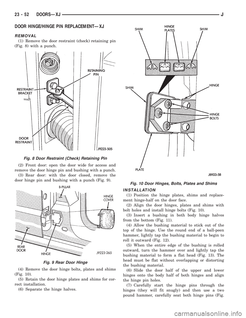
(1) Remove the door restraint (check) retaining pin
(Fig. 8) with a punch.
(2) Front door: open the door wide for access and
remove the door hinge pin and bushing with a punch.
(3) Rear door: with the door closed, remove the
door hinge pin and bushing with a punch (Fig. 9).
(4) Remove the door hinge bolts, plates and shims
(Fig. 10).
(5) Retain the door hinge plates and shims for cor-
rect installation.
(6) Separate the hinge halves.
INSTALLATION
(1) Position the hinge plates, shims and replace-
ment hinge-half on the door face.
(2) Align the door hinges, plates and shims with
bolt holes and install hinge bolts (Fig. 10).
(3) Insert a bushing in both body hinge halves
from the bottom (Fig. 11).
(4) Allow the bushing material to stick out of the
top of the hinge. Use the round end of a ball-peen
hammer, lightly tap the bushing material to begin to
roll it outward (Fig. 12).
(5) When the entire edge of the bushing is rolled
outward, turn the hammer over and lightly tap the
bushing material to form a flat head (Fig. 13). The
head must be flat without overlapping or distorting
the bushing material.
(6) Slide the door half of the upper and lower
hinges onto the body half of both hinges and align
the hinge pin holes.
(7) Carefully start the hinge pins through the
hinges (they will fit snugly) and then use a two
pound hammer, carefully seat both hinge pins (Fig.
Fig. 8 Door Restraint (Check) Retaining Pin
Fig. 9 Rear Door Hinge
Fig. 10 Door Hinges, Bolts, Plates and Shims
23 - 52 DOORSÐXJJ
Page 1984 of 2158
STATIONARY WINDOW GLASS
INDEX
page page
Interior Rearview MirrorÐXJ Removal and
Installation............................. 66
Interior Rearview Mirror Support Bracket
ReplacementÐXJ Preparation and Installation . . . 66
Description and Operation.......... ..........67
InstallationÐShort Method.......... ..........69
InstallationÐExtended Method........ ........71Rear Door Stationary Window Glass...... ......72
Rear Quarter Vent Window GlassÐXJ Removal
and Installation............. .............73
Rear Quarter Window Glass/Rear Quarter Plastic
InsertÐXJ Removal and Installation..... .....73
INTERIOR REARVIEW MIRRORÐXJ
MIRROR REMOVAL
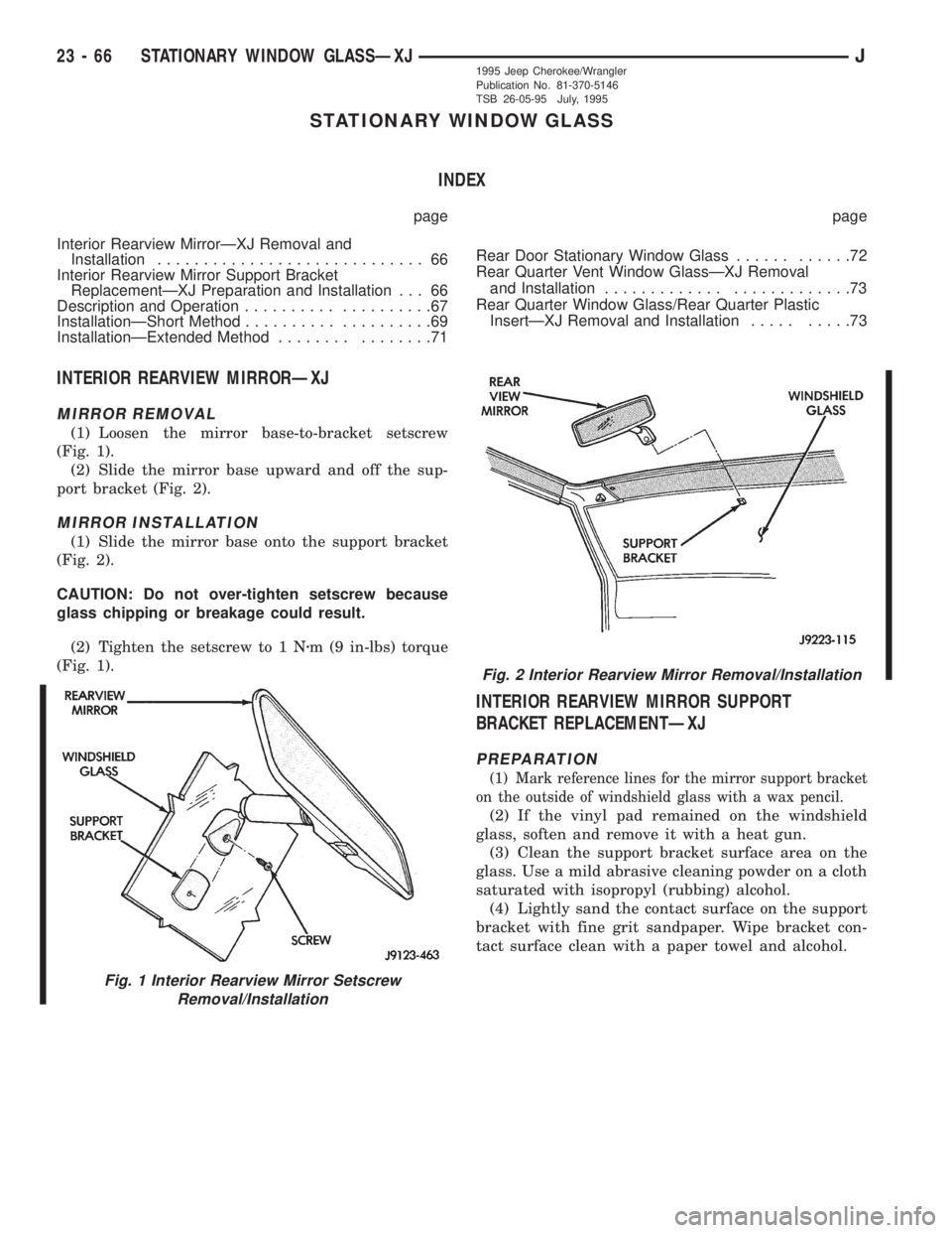
(1) Loosen the mirror base-to-bracket setscrew
(Fig. 1).
(2) Slide the mirror base upward and off the sup-
port bracket (Fig. 2).
MIRROR INSTALLATION
(1) Slide the mirror base onto the support bracket
(Fig. 2).
CAUTION: Do not over-tighten setscrew because
glass chipping or breakage could result.
(2) Tighten the setscrew to 1 Nzm (9 in-lbs) torque
(Fig. 1).
INTERIOR REARVIEW MIRROR SUPPORT
BRACKET REPLACEMENTÐXJ
PREPARATION
(1) Mark reference lines for the mirror support bracket
on the outside of windshield glass with a wax pencil.
(2) If the vinyl pad remained on the windshield
glass, soften and remove it with a heat gun.
(3) Clean the support bracket surface area on the
glass. Use a mild abrasive cleaning powder on a cloth
saturated with isopropyl (rubbing) alcohol.
(4) Lightly sand the contact surface on the support
bracket with fine grit sandpaper. Wipe bracket con-
tact surface clean with a paper towel and alcohol.
Fig. 1 Interior Rearview Mirror Setscrew
Removal/Installation
Fig. 2 Interior Rearview Mirror Removal/Installation
23 - 66 STATIONARY WINDOW GLASSÐXJJ1995 Jeep Cherokee/Wrangler
Publication No. 81-370-5146
TSB 26-05-95 July, 1995
Page 2037 of 2158
(8) Return the tape stripe/decal back to its original
position. If a wetting solution is used, position the
adhesive side of the tape stripe/decal on the panel.
Apply wetting solution to the outside of the tape
stripe/decal. Use firm strokes with a squeegee to ad-
here the tape stripe/decal to the body.
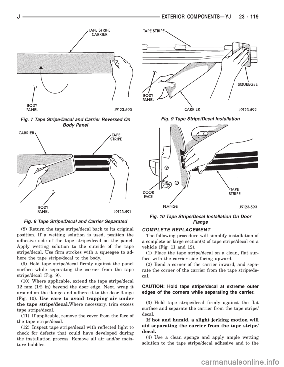
(9) Hold tape stripe/decal firmly against the panel
surface while separating the carrier from the tape
stripe/decal (Fig. 9).
(10) Where applicable, extend the tape stripe/decal
12 mm (1/2 in) beyond the door edge. Next, wrap it
around on the flange and adhere it to the door flange
(Fig. 10).Use care to avoid trapping air under
the tape stripe/decal.Where necessary, trim excess
tape stripe/decal.
(11) If applicable, remove the cover from the face of
the tape stripe/decal.
(12) Inspect tape stripe/decal with reflected light to
check for defects that could have developed during
the installation process. Remove all air and/or mois-
ture bubbles.COMPLETE REPLACEMENT
The following procedure will simplify installation of
a complete or large section(s) of tape stripe/decal on a
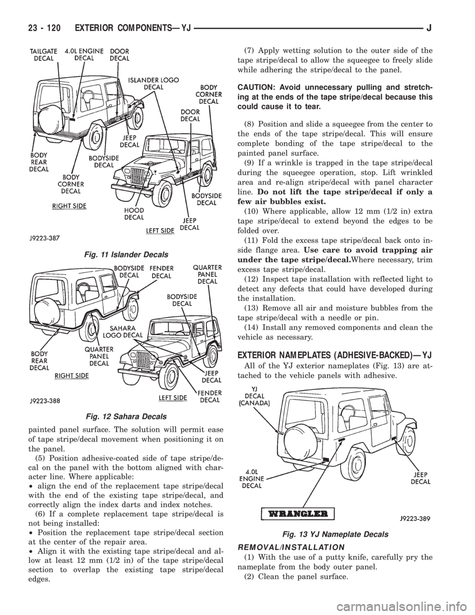
vehicle (Fig. 11 and 12).
(1) Place the tape stripe/decal on a clean, flat sur-
face with the carrier side facing upward.
(2) Bend a corner of the carrier inward, and sepa-
rate the corner of the carrier from the tape stripe/de-
cal.
CAUTION: Hold tape stripe/decal at extreme outer
edges of the corners while separating the carrier.
(3) Hold tape stripe/decal firmly against the flat
surface and separate the carrier from the tape stripe/
decal.
If hot and humid, a slight jerking motion will
aid separating the carrier from the tape stripe/
decal.
(4) Use a clean sponge and apply ample wetting
solution to the tape stripe/decal adhesive and to the
Fig. 7 Tape Stripe/Decal and Carrier Reversed On
Body Panel
Fig. 8 Tape Stripe/Decal and Carrier Separated
Fig. 9 Tape Stripe/Decal Installation
Fig. 10 Tape Stripe/Decal Installation On Door
Flange
JEXTERIOR COMPONENTSÐYJ 23 - 119
Page 2038 of 2158
painted panel surface. The solution will permit ease
of tape stripe/decal movement when positioning it on
the panel.
(5) Position adhesive-coated side of tape stripe/de-
cal on the panel with the bottom aligned with char-
acter line. Where applicable:
²align the end of the replacement tape stripe/decal
with the end of the existing tape stripe/decal, and
correctly align the index darts and index notches.
(6) If a complete replacement tape stripe/decal is
not being installed:
²Position the replacement tape stripe/decal section
at the center of the repair area.
²Align it with the existing tape stripe/decal and al-
low at least 12 mm (1/2 in) of the tape stripe/decal
section to overlap the existing tape stripe/decal
edges.(7) Apply wetting solution to the outer side of the
tape stripe/decal to allow the squeegee to freely slide
while adhering the stripe/decal to the panel.
CAUTION: Avoid unnecessary pulling and stretch-
ing at the ends of the tape stripe/decal because this
could cause it to tear.
(8) Position and slide a squeegee from the center to
the ends of the tape stripe/decal. This will ensure
complete bonding of the tape stripe/decal to the
painted panel surface.
(9) If a wrinkle is trapped in the tape stripe/decal
during the squeegee operation, stop. Lift wrinkled
area and re-align stripe/decal with panel character
line.Do not lift the tape stripe/decal if only a
few air bubbles exist.
(10) Where applicable, allow 12 mm (1/2 in) extra
tape stripe/decal to extend beyond the edges to be
folded over.
(11) Fold the excess tape stripe/decal back onto in-
side flange area.Use care to avoid trapping air
under the tape stripe/decal.Where necessary, trim
excess tape stripe/decal.
(12) Inspect tape installation with reflected light to
detect any defects that could have developed during
the installation.
(13) Remove all air and moisture bubbles from the
tape stripe/decal with a needle or pin.
(14) Install any removed components and clean the
vehicle as necessary.
EXTERIOR NAMEPLATES (ADHESIVE-BACKED)ÐYJ
All of the YJ exterior nameplates (Fig. 13) are at-
tached to the vehicle panels with adhesive.
REMOVAL/INSTALLATION
(1) With the use of a putty knife, carefully pry the
nameplate from the body outer panel.
(2) Clean the panel surface.
Fig. 11 Islander Decals
Fig. 12 Sahara Decals
Fig. 13 YJ Nameplate Decals
23 - 120 EXTERIOR COMPONENTSÐYJJ
Page 2058 of 2158
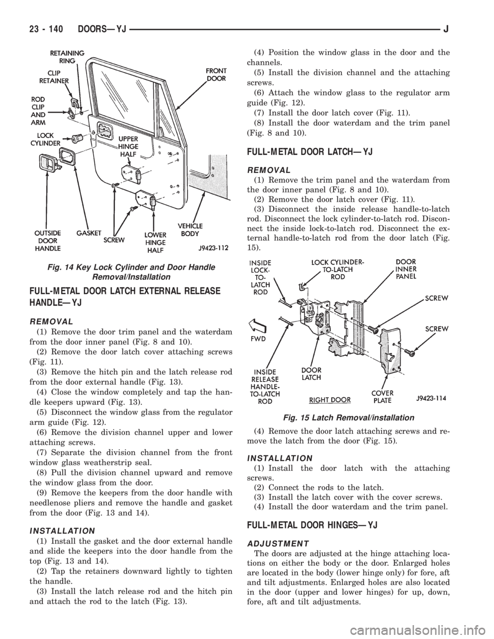
FULL-METAL DOOR LATCH EXTERNAL RELEASE
HANDLEÐYJ
REMOVAL
(1) Remove the door trim panel and the waterdam
from the door inner panel (Fig. 8 and 10).
(2) Remove the door latch cover attaching screws
(Fig. 11).
(3) Remove the hitch pin and the latch release rod
from the door external handle (Fig. 13).
(4) Close the window completely and tap the han-
dle keepers upward (Fig. 13).
(5) Disconnect the window glass from the regulator
arm guide (Fig. 12).
(6) Remove the division channel upper and lower
attaching screws.
(7) Separate the division channel from the front
window glass weatherstrip seal.
(8) Pull the division channel upward and remove
the window glass from the door.
(9) Remove the keepers from the door handle with
needlenose pliers and remove the handle and gasket
from the door (Fig. 13 and 14).
INSTALLATION
(1) Install the gasket and the door external handle
and slide the keepers into the door handle from the
top (Fig. 13 and 14).
(2) Tap the retainers downward lightly to tighten
the handle.
(3) Install the latch release rod and the hitch pin
and attach the rod to the latch (Fig. 13).(4) Position the window glass in the door and the
channels.
(5) Install the division channel and the attaching
screws.
(6) Attach the window glass to the regulator arm
guide (Fig. 12).
(7) Install the door latch cover (Fig. 11).
(8) Install the door waterdam and the trim panel
(Fig. 8 and 10).
FULL-METAL DOOR LATCHÐYJ
REMOVAL
(1) Remove the trim panel and the waterdam from
the door inner panel (Fig. 8 and 10).
(2) Remove the door latch cover (Fig. 11).
(3) Disconnect the inside release handle-to-latch
rod. Disconnect the lock cylinder-to-latch rod. Discon-
nect the inside lock-to-latch rod. Disconnect the ex-
ternal handle-to-latch rod from the door latch (Fig.
15).
(4) Remove the door latch attaching screws and re-
move the latch from the door (Fig. 15).
INSTALLATION
(1) Install the door latch with the attaching
screws.
(2) Connect the rods to the latch.
(3) Install the latch cover with the cover screws.
(4) Install the door waterdam and the trim panel.
FULL-METAL DOOR HINGESÐYJ
ADJUSTMENT
The doors are adjusted at the hinge attaching loca-
tions on either the body or the door. Enlarged holes
are located in the body (lower hinge only) for fore, aft
and tilt adjustments. Enlarged holes are also located
in the door (upper and lower hinges) for up, down,
fore, aft and tilt adjustments.
Fig. 14 Key Lock Cylinder and Door Handle
Removal/Installation
Fig. 15 Latch Removal/installation
23 - 140 DOORSÐYJJ
Page 2062 of 2158
STATIONARY GLASS
INDEX
page page
Hard Top Quarter Window GlassÐYJ......... 149
Rearview Mirror Retaining BracketÐYJ........ 144
Rearview MirrorÐYJ...................... 144
Stationary Glass Water Leak Detection and
RepairÐYJ........................... 150Windshield Frame Weatherstrip SealÐYJ...... 146
Windshield FrameÐYJ.................... 145
Windshield GlassÐYJ..................... 146
Windshield Reveal MoldingÐYJ............. 144
WINDSHIELD REVEAL MOLDINGÐYJ
REMOVAL
(1) Disengage the reveal molding around the pe-
rimeter of the windshield glass with an appropriate
tool.
(2) Remove the moldings from the windshield
frame.
(3) Inspect the reveal molding retainers. Replace
the molding if it has broken, distorted or ineffective
retainers.
INSTALLATION
(1) Position the reveal moldings on the windshield
frame.
(2) Attach the moldings to the frame by tapping
each molding with a rubber mallet to seat the retain-
ers.
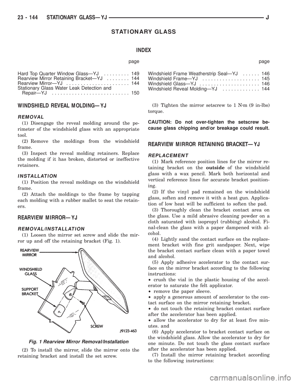
REARVIEW MIRRORÐYJ
REMOVAL/INSTALLATION
(1) Loosen the mirror set screw and slide the mir-
ror up and off the retaining bracket (Fig. 1).
(2) To install the mirror, slide the mirror onto the
retaining bracket and install the set screw.(3) Tighten the mirror setscrew to 1 Nzm (9 in-lbs)
torque.
CAUTION: Do not over-tighten the setscrew be-
cause glass chipping and/or breakage could result.
REARVIEW MIRROR RETAINING BRACKETÐYJ
REPLACEMENT
(1) Mark reference position lines for the mirror re-
taining bracket on theoutsideof the windshield
glass with a wax pencil. Mark both horizontal and
vertical reference lines for accurate bracket position-
ing.
(2) If the vinyl pad remained on the windshield
glass, soften and remove it with a heat gun. Applica-
tion of low heat will be sufficient to soften the pad.
(3) Thoroughly clean the bracket contact area on
the glass. Use a mild abrasive cleaning powder on a
cloth saturated with isopropyl (rubbing) alcohol. Fi-
nal-clean the glass with a paper dampened with al-
cohol.
(4) Lightly sand the contact surface on the replace-
ment bracket with fine grit sandpaper. Next, wipe
the bracket contact surface clean with a paper towel
and alcohol.
(5) Apply adhesive accelerator to the contact sur-
face on the mirror bracket according to the following
instructions:
²crush the vial in the plastic housing of the accel-
erator to saturate the felt applicator.
²remove the paper sleeve.
²apply a generous amount of accelerator to the con-
tact surface on the mirror retaining bracket.
²do not touch the retaining bracket contact surface
after the accelerator has been applied.
²allow the accelerator to dry for at least five min-
utes. and
(6) Apply accelerator to bracket contact surface on
the windshield glass. Allow the accelerator to dry for
one minute. Do not touch the glass contact surface
after the accelerator has been applied.
(7) Install the mirror retaining bracket according
to the following instructions:
Fig. 1 Rearview Mirror Removal/Installation
23 - 144 STATIONARY GLASSÐYJJ
Page 2076 of 2158
PAINT
INTRODUCTION
Exterior vehicle body colors are identified on the
Vehicle Code plate. The plate is located on the left
side of the dash panel in the engine compartment.
The color code location is described in the Introduc-
tion of this manual. The color names provided in the
Paint and Trim Code Description chart are the color
names used on most repair product containers. The
color names in the new vehicle ordering guides may
vary depending on vehicle line but use the same color
code.
BASE COAT/CLEAR COAT FINISH
On most vehicles a two part paint application (base
coat/clear coat) is used. Color paint that is applied to
primer is called base coat. The clear coat protects the
base coat from ultra violet light and provides a dura-
ble high gloss finish.
WET SANDING,BUFFING AND POLISHING
Minor acid etching, orange peel or smudging in
clear coat can be reduced with light wet sanding,
hand buffing and polishing. If the finish has been
wet sanded in the past, it can not be repeated. Wet
sanding operation should be performed by a trained
automotive painter.
CAUTION: Do not remove clear coat finish, if
equipped. Base coat paint must retain clear coat to
shine.
PAINTED SURFACE TOUCH-UP
When a painted metal surface has been scratched
or chipped, it should be touched-up as soon as possi-ble to avoid corrosion. For best results, use Mopar
Scratch Filler/Primer, Touch-Up Paints and Clear Top
Coat. Refer to Introduction group of this manual for
Body Code Plate information.
TOUCH-UP PROCEDURE
(1) Scrape loose paint and corrosion from inside
scratch or chip.
(2) Clean affected area with Mopar Tar/Road Oil
Remover and allow to dry.
(3) Fill the inside of the scratch or chip with a coat
of filler/primer. Do not overlap primer onto good sur-
face finish. The applicator brush should be wet
enough to puddle fill the defect without running. Do
not stroke brush applicator on body surface. Allow
the filler/ primer to dry hard.
(4) Cover the filler/primer with color touch-up
paint. Do not overlap touch-up color onto the original
color coat around the scratch or chip. Butt the new
color to the original color if possible. Do not stroke
applicator brush on body surface. Allow touch-up
paint to dry hard.
(5) On vehicles without clear coat, the touch-up
color can be lightly (600 grit) wet sanded and pol-
ished with rubbing compound.
(6) On vehicles with clear coat, Apply clear top
coat to touch-up paint with the same technique as
described in step 4. Allow clear top coat to dry hard.
If desired, step 5 can be performed on clear top coat.
23 - 158 PAINTÐXJÐYJJ
Page 2102 of 2158
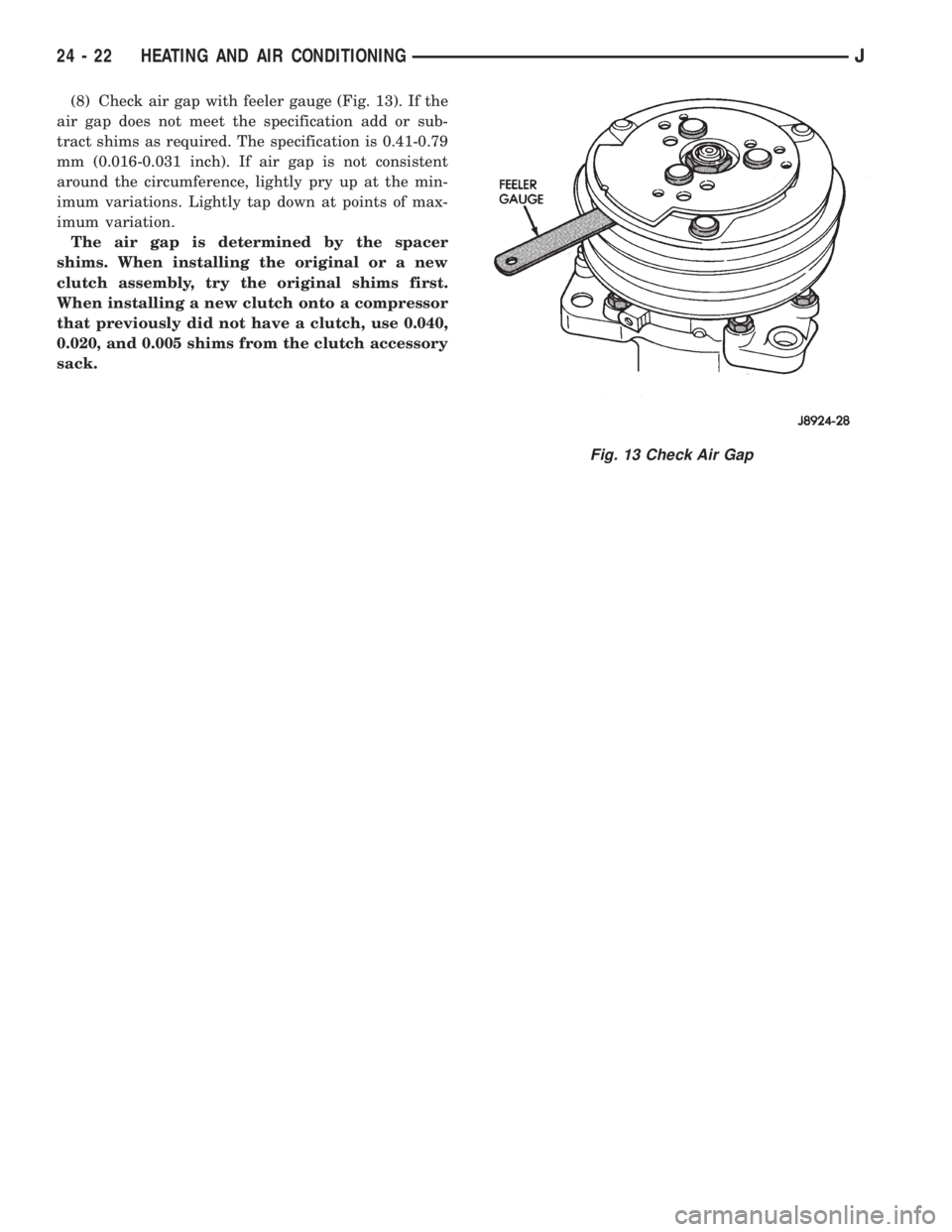
(8) Check air gap with feeler gauge (Fig. 13). If the
air gap does not meet the specification add or sub-
tract shims as required. The specification is 0.41-0.79
mm (0.016-0.031 inch). If air gap is not consistent
around the circumference, lightly pry up at the min-
imum variations. Lightly tap down at points of max-
imum variation.
The air gap is determined by the spacer
shims. When installing the original or a new
clutch assembly, try the original shims first.
When installing a new clutch onto a compressor
that previously did not have a clutch, use 0.040,
0.020, and 0.005 shims from the clutch accessory
sack.
Fig. 13 Check Air Gap
24 - 22 HEATING AND AIR CONDITIONINGJ