1995 JEEP YJ light
[x] Cancel search: lightPage 1712 of 2158
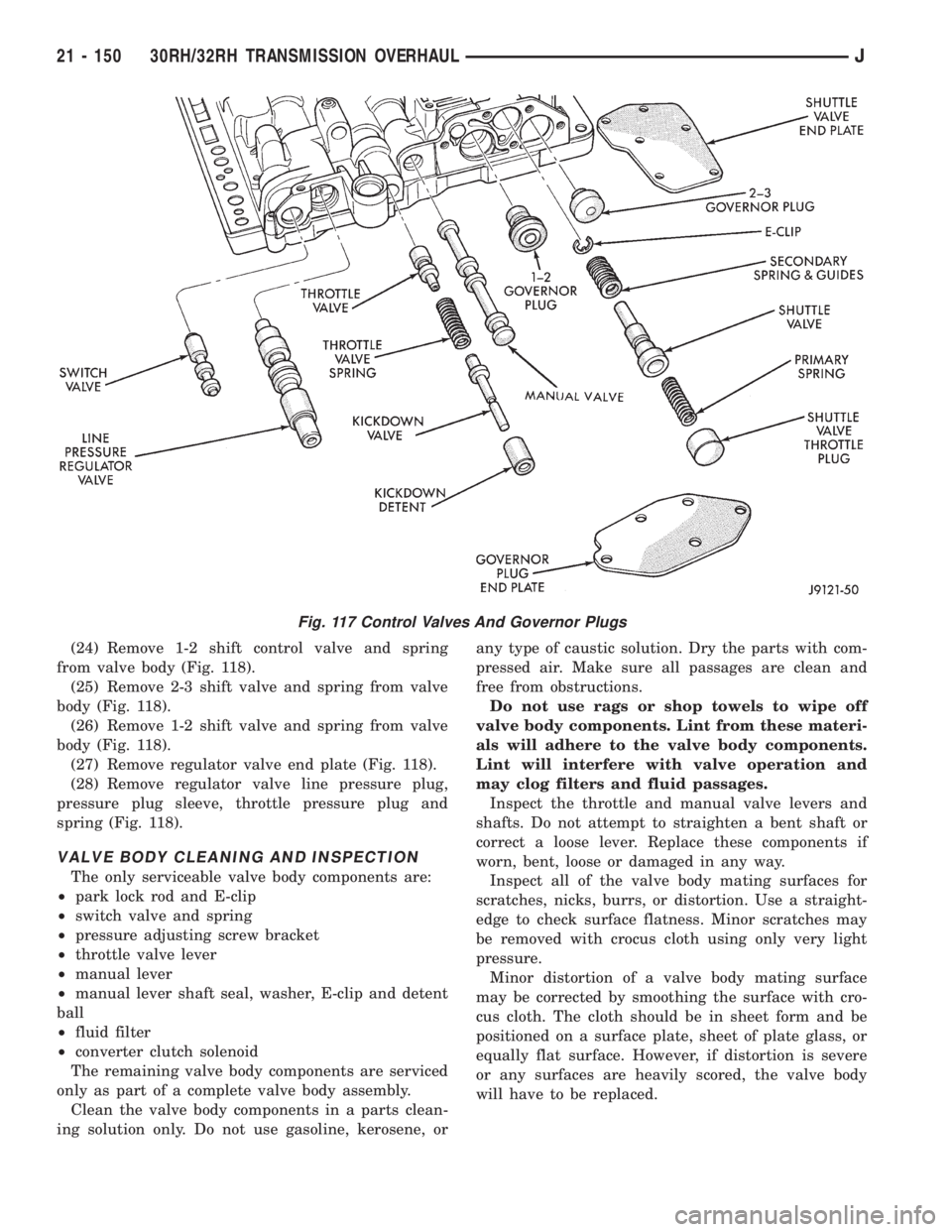
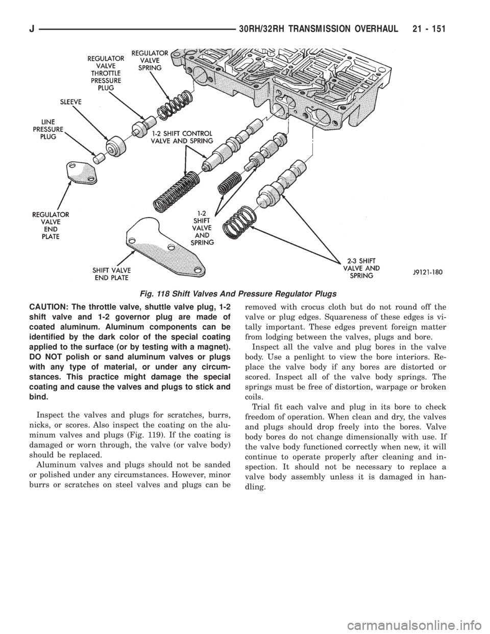
(24) Remove 1-2 shift control valve and spring
from valve body (Fig. 118).
(25) Remove 2-3 shift valve and spring from valve
body (Fig. 118).
(26) Remove 1-2 shift valve and spring from valve
body (Fig. 118).
(27) Remove regulator valve end plate (Fig. 118).
(28) Remove regulator valve line pressure plug,
pressure plug sleeve, throttle pressure plug and
spring (Fig. 118).
VALVE BODY CLEANING AND INSPECTION
The only serviceable valve body components are:
²park lock rod and E-clip
²switch valve and spring
²pressure adjusting screw bracket
²throttle valve lever
²manual lever
²manual lever shaft seal, washer, E-clip and detent
ball
²fluid filter
²converter clutch solenoid
The remaining valve body components are serviced
only as part of a complete valve body assembly.
Clean the valve body components in a parts clean-
ing solution only. Do not use gasoline, kerosene, orany type of caustic solution. Dry the parts with com-
pressed air. Make sure all passages are clean and
free from obstructions.
Do not use rags or shop towels to wipe off
valve body components. Lint from these materi-
als will adhere to the valve body components.
Lint will interfere with valve operation and
may clog filters and fluid passages.
Inspect the throttle and manual valve levers and
shafts. Do not attempt to straighten a bent shaft or
correct a loose lever. Replace these components if
worn, bent, loose or damaged in any way.
Inspect all of the valve body mating surfaces for
scratches, nicks, burrs, or distortion. Use a straight-
edge to check surface flatness. Minor scratches may
be removed with crocus cloth using only very light
pressure.
Minor distortion of a valve body mating surface
may be corrected by smoothing the surface with cro-
cus cloth. The cloth should be in sheet form and be
positioned on a surface plate, sheet of plate glass, or
equally flat surface. However, if distortion is severe
or any surfaces are heavily scored, the valve body
will have to be replaced.
Fig. 117 Control Valves And Governor Plugs
21 - 150 30RH/32RH TRANSMISSION OVERHAULJ
Page 1713 of 2158
CAUTION: The throttle valve, shuttle valve plug, 1-2
shift valve and 1-2 governor plug are made of
coated aluminum. Aluminum components can be
identified by the dark color of the special coating
applied to the surface (or by testing with a magnet).
DO NOT polish or sand aluminum valves or plugs
with any type of material, or under any circum-
stances. This practice might damage the special
coating and cause the valves and plugs to stick and
bind.
Inspect the valves and plugs for scratches, burrs,
nicks, or scores. Also inspect the coating on the alu-
minum valves and plugs (Fig. 119). If the coating is
damaged or worn through, the valve (or valve body)
should be replaced.
Aluminum valves and plugs should not be sanded
or polished under any circumstances. However, minor
burrs or scratches on steel valves and plugs can beremoved with crocus cloth but do not round off the
valve or plug edges. Squareness of these edges is vi-
tally important. These edges prevent foreign matter
from lodging between the valves, plugs and bore.
Inspect all the valve and plug bores in the valve
body. Use a penlight to view the bore interiors. Re-
place the valve body if any bores are distorted or
scored. Inspect all of the valve body springs. The
springs must be free of distortion, warpage or broken
coils.
Trial fit each valve and plug in its bore to check
freedom of operation. When clean and dry, the valves
and plugs should drop freely into the bores. Valve
body bores do not change dimensionally with use. If
the valve body functioned correctly when new, it will
continue to operate properly after cleaning and in-
spection. It should not be necessary to replace a
valve body assembly unless it is damaged in han-
dling.
Fig. 118 Shift Valves And Pressure Regulator Plugs
J30RH/32RH TRANSMISSION OVERHAUL 21 - 151
Page 1716 of 2158
(20) Insert line pressure adjusting screw in adjust-
ing screw bracket (Fig. 107).
(21) Install spring on end of line pressure regula-
tor valve.
(22) Install switch valve spring on tang at end of
adjusting screw bracket (Fig. 107).
(23) Position adjusting screw bracket on valve
body. Align valve springs and press bracket into
place. Install short, upper bracket screws first and
long bottom screw last. Verify that valve springs and
bracket are properly aligned. Then tighten all three
bracket screws to 4 Nzm (35 in. lbs.) torque.
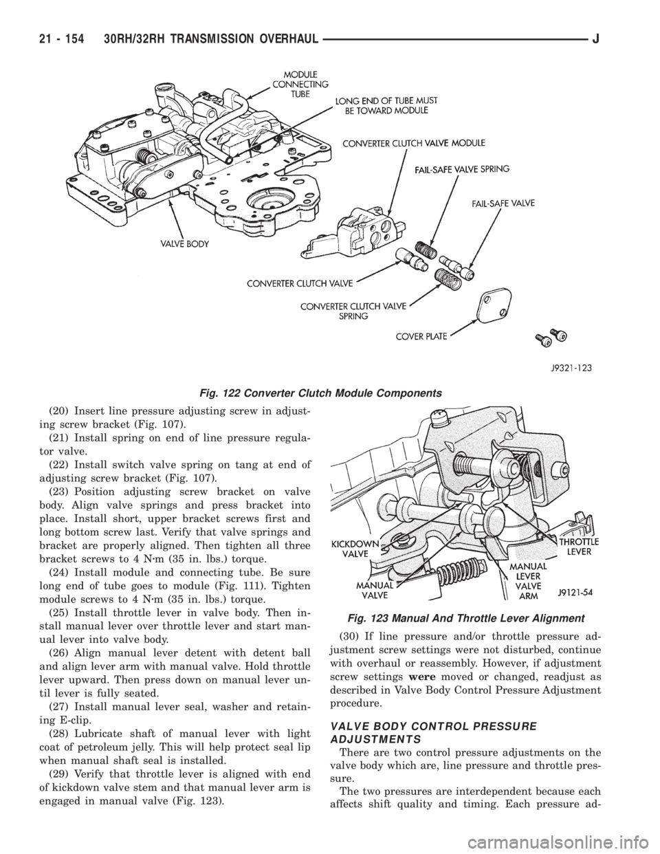
(24) Install module and connecting tube. Be sure
long end of tube goes to module (Fig. 111). Tighten
module screws to 4 Nzm (35 in. lbs.) torque.
(25) Install throttle lever in valve body. Then in-
stall manual lever over throttle lever and start man-
ual lever into valve body.
(26) Align manual lever detent with detent ball
and align lever arm with manual valve. Hold throttle
lever upward. Then press down on manual lever un-
til lever is fully seated.
(27) Install manual lever seal, washer and retain-
ing E-clip.
(28) Lubricate shaft of manual lever with light
coat of petroleum jelly. This will help protect seal lip
when manual shaft seal is installed.
(29) Verify that throttle lever is aligned with end
of kickdown valve stem and that manual lever arm is
engaged in manual valve (Fig. 123).(30) If line pressure and/or throttle pressure ad-
justment screw settings were not disturbed, continue
with overhaul or reassembly. However, if adjustment
screw settingsweremoved or changed, readjust as
described in Valve Body Control Pressure Adjustment
procedure.
VALVE BODY CONTROL PRESSURE
ADJUSTMENTS
There are two control pressure adjustments on the
valve body which are, line pressure and throttle pres-
sure.
The two pressures are interdependent because each
affects shift quality and timing. Each pressure ad-
Fig. 122 Converter Clutch Module Components
Fig. 123 Manual And Throttle Lever Alignment
21 - 154 30RH/32RH TRANSMISSION OVERHAULJ
Page 1718 of 2158
OVERRUNNING CLUTCH INSTALLATION
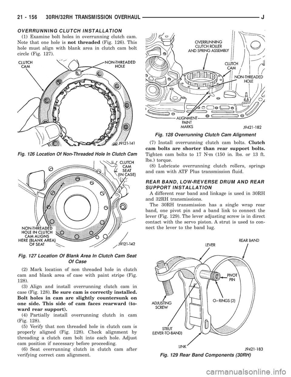
(1) Examine bolt holes in overrunning clutch cam.
Note that one hole isnot threaded(Fig. 126). This
hole must align with blank area in clutch cam bolt
circle (Fig. 127).
(2) Mark location of non threaded hole in clutch
cam and blank area of case with paint stripe (Fig.
128).
(3) Align and install overrunning clutch cam in
case (Fig. 128).Be sure cam is correctly installed.
Bolt holes in cam are slightly countersunk on
one side. This side of cam faces rearward (to-
ward rear support).
(4) Partially install overrunning clutch in cam
(Fig. 128).
(5) Verify that non threaded hole in clutch cam is
properly aligned (Fig. 128). Check alignment by
threading a clutch cam bolt into each hole. Adjust
cam position if necessary before proceeding.
(6) Seat overrunning clutch in clutch cam after
verifying correct cam alignment.(7) Install overrunning clutch cam bolts.Clutch
cam bolts are shorter than rear support bolts.
Tighten cam bolts to 17 Nzm (150 in. lbs. or 13 ft.
lbs.) torque.
(8) Lubricate overrunning clutch rollers, springs
and cam with ATF Plus transmission fluid.
REAR BAND, LOW-REVERSE DRUM AND REAR
SUPPORT INSTALLATION
A different rear band and linkage is used in 30RH
and 32RH transmissions.
The 30RH transmission has a single wrap rear
band, one pivot pin and a band link to connect the
lever (Fig. 129). The lever adjusting screw is in direct
contact with the servo piston. A strut is used to con-
nect the lever to the band lug.
Fig. 126 Location Of Non-Threaded Hole In Clutch Cam
Fig. 127 Location Of Blank Area In Clutch Cam Seat
Of Case
Fig. 128 Overrunning Clutch Cam Alignment
Fig. 129 Rear Band Components (30RH)
21 - 156 30RH/32RH TRANSMISSION OVERHAULJ
Page 1719 of 2158
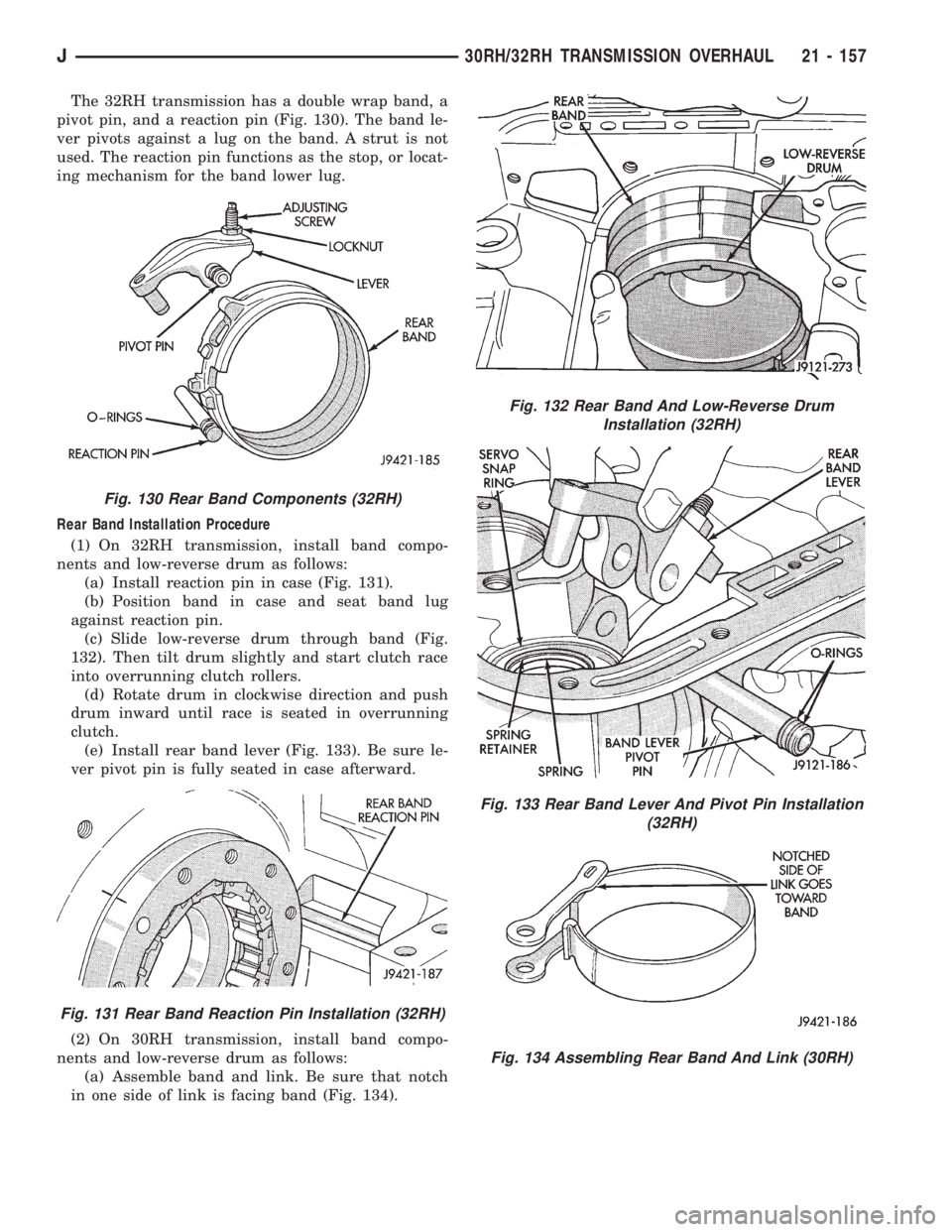
The 32RH transmission has a double wrap band, a
pivot pin, and a reaction pin (Fig. 130). The band le-
ver pivots against a lug on the band. A strut is not
used. The reaction pin functions as the stop, or locat-
ing mechanism for the band lower lug.
Rear Band Installation Procedure
(1) On 32RH transmission, install band compo-
nents and low-reverse drum as follows:
(a) Install reaction pin in case (Fig. 131).
(b) Position band in case and seat band lug
against reaction pin.
(c) Slide low-reverse drum through band (Fig.
132). Then tilt drum slightly and start clutch race
into overrunning clutch rollers.
(d) Rotate drum in clockwise direction and push
drum inward until race is seated in overrunning
clutch.
(e) Install rear band lever (Fig. 133). Be sure le-
ver pivot pin is fully seated in case afterward.
(2) On 30RH transmission, install band compo-
nents and low-reverse drum as follows:
(a) Assemble band and link. Be sure that notch
in one side of link is facing band (Fig. 134).
Fig. 130 Rear Band Components (32RH)
Fig. 131 Rear Band Reaction Pin Installation (32RH)
Fig. 132 Rear Band And Low-Reverse Drum
Installation (32RH)
Fig. 133 Rear Band Lever And Pivot Pin Installation
(32RH)
Fig. 134 Assembling Rear Band And Link (30RH)
J30RH/32RH TRANSMISSION OVERHAUL 21 - 157
Page 1720 of 2158
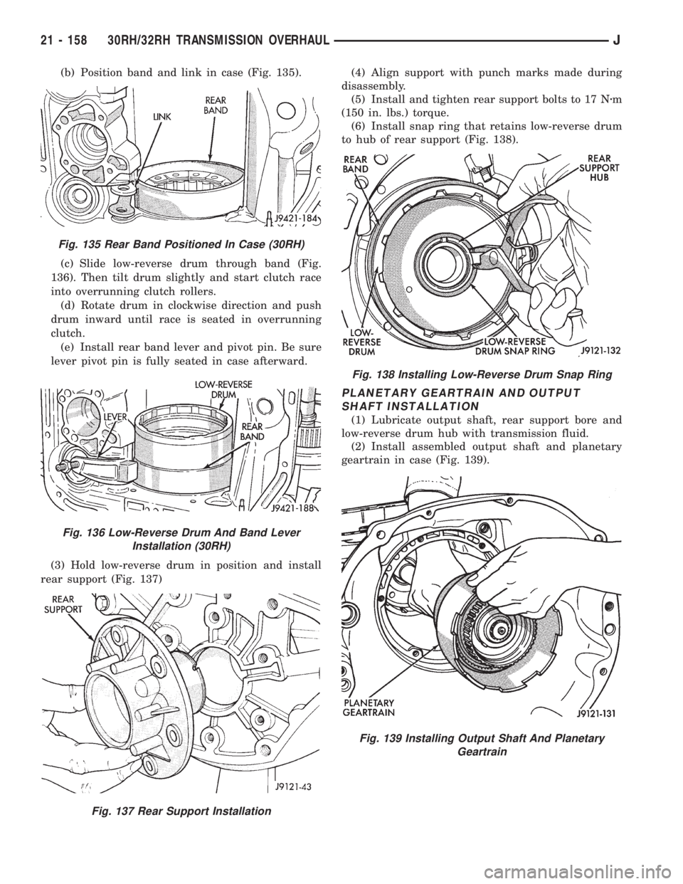
(b) Position band and link in case (Fig. 135).
(c) Slide low-reverse drum through band (Fig.
136). Then tilt drum slightly and start clutch race
into overrunning clutch rollers.
(d) Rotate drum in clockwise direction and push
drum inward until race is seated in overrunning
clutch.
(e) Install rear band lever and pivot pin. Be sure
lever pivot pin is fully seated in case afterward.
(3) Hold low-reverse drum in position and install
rear support (Fig. 137)(4) Align support with punch marks made during
disassembly.
(5) Install and tighten rear support bolts to 17 Nzm
(150 in. lbs.) torque.
(6) Install snap ring that retains low-reverse drum
to hub of rear support (Fig. 138).
PLANETARY GEARTRAIN AND OUTPUT
SHAFT INSTALLATION
(1) Lubricate output shaft, rear support bore and
low-reverse drum hub with transmission fluid.
(2) Install assembled output shaft and planetary
geartrain in case (Fig. 139).
Fig. 135 Rear Band Positioned In Case (30RH)
Fig. 136 Low-Reverse Drum And Band Lever
Installation (30RH)
Fig. 137 Rear Support Installation
Fig. 138 Installing Low-Reverse Drum Snap Ring
Fig. 139 Installing Output Shaft And Planetary
Geartrain
21 - 158 30RH/32RH TRANSMISSION OVERHAULJ
Page 1732 of 2158

The manual valve, 1-2 shift valve, primary regula-
tor valve, accumulator control valve, check balls, so-
lenoids and oil strainers are located in the lower
body section (Fig. 10). The remaining control and
shift valves plus check balls and one additional oil
strainer are located in the upper body section (Fig.
11).
Manual Valve
The manual valve is operated by the gearshift link-
age. The valve diverts fluid to the apply circuits ac-
cording to shift lever position.Primary Regulator Valve
The primary regulator valve (Fig. 13) modulates
line pressure to the clutches and brakes according to
engine load. The valve is actuated by throttle valve
pressure.
During high load operation, the valve increases line
pressure to maintain positive clutch and brake en-
gagement. At light load, the valve decreases line
pressure just enough to maintain smooth engage-
ment.
Fig. 10 Upper Body Components
Fig. 11 Lower Body Components
21 - 170 AW-4 AUTOMATIC TRANSMISSIONJ
Page 1864 of 2158
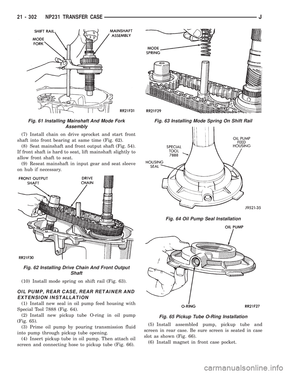
(7) Install chain on drive sprocket and start front
shaft into front bearing at same time (Fig. 62).
(8) Seat mainshaft and front output shaft (Fig. 54).
If front shaft is hard to seat, lift mainshaft slightly to
allow front shaft to seat.
(9) Reseat mainshaft in input gear and seat sleeve
on hub if necessary.
(10) Install mode spring on shift rail (Fig. 63).
OIL PUMP, REAR CASE, REAR RETAINER AND
EXTENSION INSTALLATION
(1) Install new seal in oil pump feed housing with
Special Tool 7888 (Fig. 64).
(2) Install new pickup tube O-ring in oil pump
(Fig. 65).
(3) Prime oil pump by pouring transmission fluid
into pump through pickup tube opening.
(4) Insert pickup tube in oil pump. Then attach oil
screen and connecting hose to pickup tube (Fig. 66).(5) Install assembled pump, pickup tube and
screen in rear case. Be sure screen is seated in case
slot as shown (Fig. 66).
(6) Install magnet in front case pocket.
Fig. 61 Installing Mainshaft And Mode Fork
Assembly
Fig. 62 Installing Drive Chain And Front Output
Shaft
Fig. 63 Installing Mode Spring On Shift Rail
Fig. 64 Oil Pump Seal Installation
Fig. 65 Pickup Tube O-Ring Installation
21 - 302 NP231 TRANSFER CASEJ