1995 JEEP YJ light
[x] Cancel search: lightPage 1517 of 2158
CLEAN AND INSPECTION
(1) Wash all components in clean solvent and dry
with compressed air.
(2) Check for scores, nicks or burrs on the rack pis-
ton finished surface. Slight wear is normal on the
worm gear surfaces.
ASSEMBLE
(1) Install O-ring seal and teflon ring and lubricate
with power steering fluid.
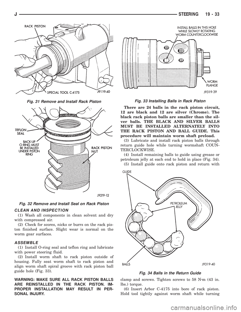
(2) Install worm shaft to rack piston outside of
housing. Fully seat worm shaft to rack piston and
align worm shaft spiral groove with rack piston ball
guide hole (Fig. 33).
WARNING: MAKE SURE ALL RACK PISTON BALLS
ARE REINSTALLED IN THE RACK PISTON. IM-
PROPER INSTALLATION MAY RESULT IN PER-
SONAL INJURY.There are 24 balls in the rack piston circuit,
12 are black and 12 are silver (Chrome). The
black rack piston balls are smaller than the sil-
ver balls. THE BLACK AND SILVER BALLS
MUST BE INSTALLED ALTERNATELY INTO
THE RACK PISTON AND BALL GUIDE. This
procedure will maintain worm shaft preload.
(3) Lubricate and install rack piston balls through
return guide hole while turning wormshaft COUN-
TERCLOCKWISE.
(4) Install remaining balls to guide using grease or
petroleum jelly at each end to hold in place (Fig. 34).
(5) Install guide onto rack piston and return with
clamp and screws. Tighten screws to 58 Nzm (43 in.
lbs.) torque.
(6) Insert Arbor C-4175 into bore of rack piston.
Hold tool tightly against worm shaft while turning
Fig. 31 Remove and Install Rack Piston
Fig. 32 Remove and Install Seal on Rack Piston
Fig. 33 Installing Balls in Rack Piston
Fig. 34 Balls in the Return Guide
JSTEERING 19 - 33
Page 1525 of 2158
(3) Hold the ball nut over a cloth. Remove the re-
maining recirculating balls by rotating the worm-
shaft back and forth.
There are a total of 50 recirculating balls
within the ball nut and the guides (25 in each
circuit).
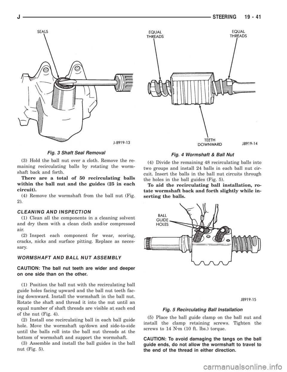
(4) Remove the wormshaft from the ball nut (Fig.
2).
CLEANING AND INSPECTION
(1) Clean all the components in a cleaning solvent
and dry them with a clean cloth and/or compressed
air.
(2) Inspect each component for wear, scoring,
cracks, nicks and surface pitting. Replace as neces-
sary.
WORMSHAFT AND BALL NUT ASSEMBLY
CAUTION: The ball nut teeth are wider and deeper
on one side than on the other.
(1) Position the ball nut with the recirculating ball
guide holes facing upward and the ball nut teeth fac-
ing downward. Install the wormshaft in the ball nut.
Rotate the shaft and thread it into the nut until an
equal number of shaft threads are visible at each end
of the nut (Fig. 4).
(2) Install one recirculating ball in each ball guide
hole. Move the wormshaft up/down and side-to-side
until the balls roll into the ball nut threads at the
bottom of wormshaft and support the wormshaft.
(3) Assemble and install the ball guides in the ball
nut (Fig. 5).(4) Divide the remaining 48 recirculating balls into
two groups and install 24 balls in each ball nut cir-
cuit. Insert the balls in the ball nut circuits through
the holes in the ball guides (Fig. 5).
To aid the recirculating ball installation, ro-
tate wormshaft back and forth slightly while in-
serting the balls.
(5) Place the ball guide clamp on the ball nut and
install the clamp retaining screws. Tighten the
screws to 14 Nzm (10 ft. lbs.) torque.
CAUTION: To avoid damaging the tangs on the ball
guide ends, do not allow the wormshaft to travel to
the end of the thread in either direction.
Fig. 3 Shaft Seal RemovalFig. 4 Wormshaft & Ball Nut
Fig. 5 Recirculating Ball Installation
JSTEERING 19 - 41
Page 1526 of 2158
(6) Lubricate the wormshaft threads with chassis
lubricant. Rotate the shaft to move it in and out of
the ball nut and distribute the lubricant.
(7) Lubricate the wormshaft upper bearing with
chassis lubricant and install it on the wormshaft.
WORMSHAFT BEARING ADJUSTMENT CAP
DISASSEMBLY
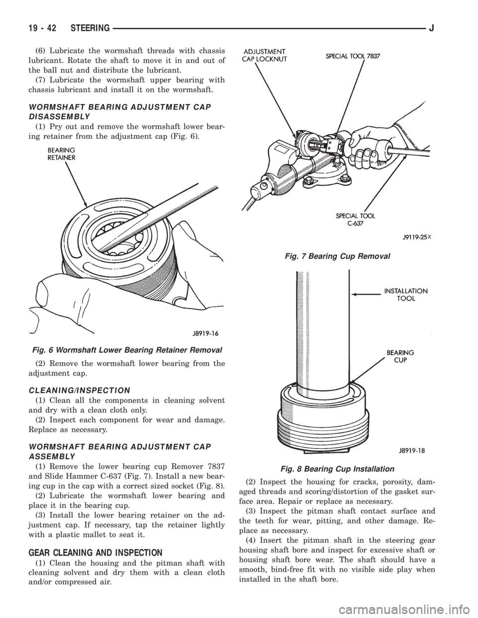
(1) Pry out and remove the wormshaft lower bear-
ing retainer from the adjustment cap (Fig. 6).
(2) Remove the wormshaft lower bearing from the
adjustment cap.
CLEANING/INSPECTION
(1) Clean all the components in cleaning solvent
and dry with a clean cloth only.
(2) Inspect each component for wear and damage.
Replace as necessary.
WORMSHAFT BEARING ADJUSTMENT CAP
ASSEMBLY
(1) Remove the lower bearing cup Remover 7837
and Slide Hammer C-637 (Fig. 7). Install a new bear-
ing cup in the cap with a correct sized socket (Fig. 8).
(2) Lubricate the wormshaft lower bearing and
place it in the bearing cup.
(3) Install the lower bearing retainer on the ad-
justment cap. If necessary, tap the retainer lightly
with a plastic mallet to seat it.
GEAR CLEANING AND INSPECTION
(1) Clean the housing and the pitman shaft with
cleaning solvent and dry them with a clean cloth
and/or compressed air.(2) Inspect the housing for cracks, porosity, dam-
aged threads and scoring/distortion of the gasket sur-
face area. Repair or replace as necessary.
(3) Inspect the pitman shaft contact surface and
the teeth for wear, pitting, and other damage. Re-
place as necessary.
(4) Insert the pitman shaft in the steering gear
housing shaft bore and inspect for excessive shaft or
housing shaft bore wear. The shaft should have a
smooth, bind-free fit with no visible side play when
installed in the shaft bore.
Fig. 6 Wormshaft Lower Bearing Retainer Removal
Fig. 7 Bearing Cup Removal
X
Fig. 8 Bearing Cup Installation
19 - 42 STEERINGJ
Page 1537 of 2158
(14) Remove the Interlock cable from the steering
column. Refer to Automatic Transmission Shifter/Ig-
nition Interlock in this group.
(15) Remove the column. Use care to avoid damag-
ing the paint or trim.
INSTALLATION
CAUTION: Bumping, jolting and hammering on the
steering column shaft and gear shift tube must be
avoided during all service procedures.
(1) With the front wheels in the straight ahead po-
sition. Align and install the column to coupler.Do
not apply force at the top of the steering col-
umn shaft.(2) Ensure the ground clip is on the left spacer slot
(Fig. 17).
(3) Install the Interlock cable from the steering col-
umn. Refer to Automatic Transmission Shifter/Igni-
tion Interlock in this group.
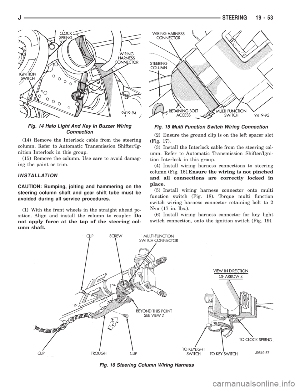
(4) Install wiring harness connections to steering
column (Fig. 16).Ensure the wiring is not pinched
and all connections are correctly locked in
place.
(5) Install wiring harness connector onto multi
function switch (Fig. 18). Torque multi function
switch wiring harness connector retaining bolt to 2
Nzm (17 in. lbs.).
(6) Install wiring harness connector for key light
switch connection, onto the ignition switch (Fig. 19).
Fig. 15 Multi Function Switch Wiring Connection
Fig. 16 Steering Column Wiring Harness
J9519-57
Fig. 14 Halo Light And Key In Buzzer Wiring
Connection
JSTEERING 19 - 53
Page 1538 of 2158
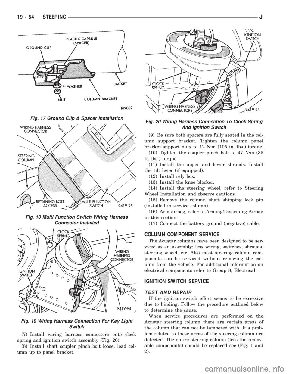
(7) Install wiring harness connectors onto clock
spring and ignition switch assembly (Fig. 20).
(8) Install shaft coupler pinch bolt loose, load col-
umn up to panel bracket.(9) Be sure both spacers are fully seated in the col-
umn support bracket. Tighten the column panel
bracket support nuts to 12 Nzm (105 in. lbs.) torque.
(10) Tighten the coupler pinch bolt to 47 Nzm (35
ft. lbs.) torque.
(11) Install the upper and lower shrouds. Install
the tilt lever (if equipped).
(12) Install rely box.
(13) Install the knee blocker.
(14) Install the steering wheel, refer to Steering
Wheel Installation and observe cautions.
(15) Remove the column shaft shipping lock pin
(installed in service column).
(16) Arm airbag, refer to Arming/Disarming Airbag
in this section.
(17) Connect the battery ground (negative) cable.
COLUMN COMPONENT SERVICE
The Acustar columns have been designed to be ser-
viced as an assembly; less wiring, switches, shrouds,
steering wheel, etc. Also most steering column com-
ponents can be serviced without removing the col-
umn from the vehicle. For additional information on
electrical components refer to Group 8, Electrical.
IGNITION SWITCH SERVICE
TEST AND REPAIR
If the ignition switch effort seems to be excessive
due to binding. Follow the procedure outlined below
to determine the cause.
When service procedures are performed on the
Acustar steering column there are certain areas of
the column that can not be tampered with. If a prob-
lem related to these areas of the steering column are
detected. The entire steering column (less the remov-
able components) should be replaced see (Fig. 1 and
2).
Fig. 17 Ground Clip & Spacer Installation
Fig. 18 Multi Function Switch Wiring Harness
Connector Installed
Fig. 19 Wiring Harness Connection For Key Light
Switch
Fig. 20 Wiring Harness Connection To Clock Spring
And Ignition Switch
19 - 54 STEERINGJ
Page 1539 of 2158
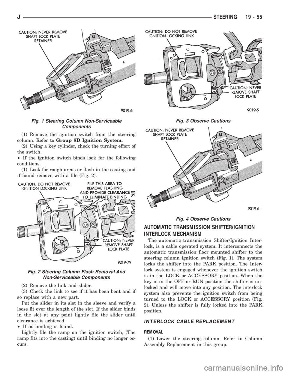
(1) Remove the ignition switch from the steering
column. Refer toGroup 8D Ignition System.
(2) Using a key cylinder, check the turning effort of
the switch.
²If the ignition switch binds look for the following
conditions.
(1) Look for rough areas or flash in the casting and
if found remove with a file (Fig. 2).
(2) Remove the link and slider.
(3) Check the link to see if it has been bent and if
so replace with a new part.
Put the slider in its slot in the sleeve and verify a
loose fit over the length of the slot. If the slider binds
in the slot at any point lightly file the slider until
clearance is achieved.
²If no binding is found.
Lightly file the ramp on the ignition switch, (The
ramp fits into the casting) until binding no longer oc-
curs.
AUTOMATIC TRANSMISSION SHIFTER/IGNITION
INTERLOCK MECHANISM
The automatic transmission Shifter/Ignition Inter-
lock, is a cable operated system. It interconnects the
automatic transmission floor mounted shifter to the
steering column ignition switch (Fig. 1). The system
locks the shifter into the PARK position. The Inter-
lock system is engaged whenever the ignition switch
is in the LOCK or ACCESSORY position. When the
key is in the OFF or RUN position the shifter is un-
locked and will move into any position. The interlock
system also prevents the ignition switch from being
turned to the LOCK or ACCESSORY position (Fig.
2). Unless the shifter is fully locked into the PARK
position.
INTERLOCK CABLE REPLACEMENT
REMOVAL
(1) Lower the steering column. Refer to Column
Assembly Replacement in this group.
Fig. 1 Steering Column Non-Serviceable
Components
Fig. 2 Steering Column Flash Removal And
Non-Serviceable Components
Fig. 3 Observe Cautions
Fig. 4 Observe Cautions
JSTEERING 19 - 55
Page 1557 of 2158
(36) If equipped, install the cruise control wire har-
ness. Install the turn signal stalk by pushing it
straight into the column.
(37) Insert the hazard warning knob in the hazard
warning switch and press it inward. Align and install
the turn signal switch retaining screws. Ensure that
the turn signal switch is properly seated before tight-
ening the screws. Tighten the screws to 4 Nzm (33 in.
lbs.) torque. Thread the hazard warning switch knob
into the switch and pull the knob outward.
(38) Install and seat the upper bearing race in the
key/lock cylinder housing.
(39) Install the upper bearing preload spring, the
canceling cam and the lockplate.
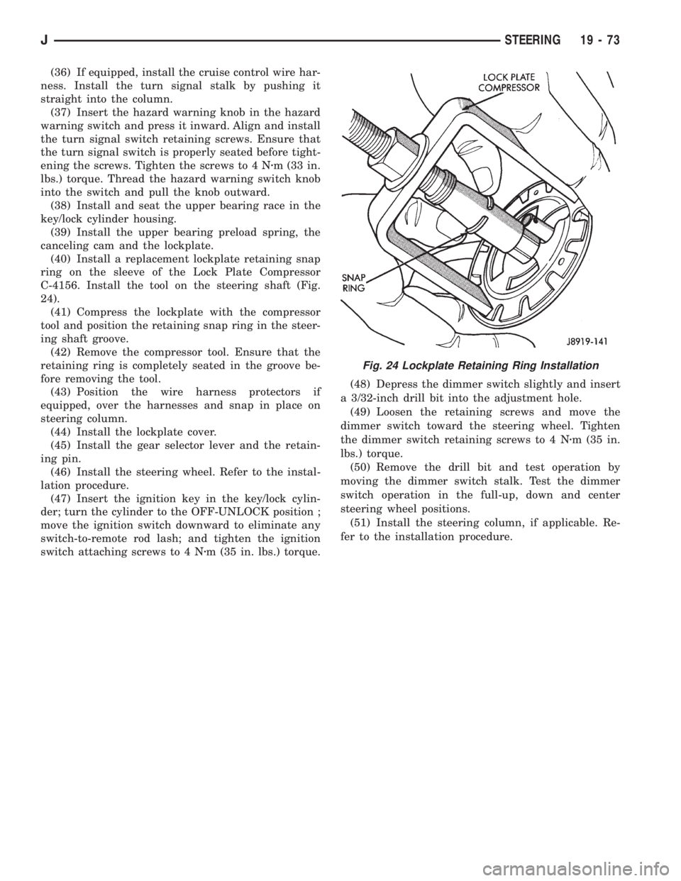
(40) Install a replacement lockplate retaining snap
ring on the sleeve of the Lock Plate Compressor
C-4156. Install the tool on the steering shaft (Fig.
24).
(41) Compress the lockplate with the compressor
tool and position the retaining snap ring in the steer-
ing shaft groove.
(42) Remove the compressor tool. Ensure that the
retaining ring is completely seated in the groove be-
fore removing the tool.
(43) Position the wire harness protectors if
equipped, over the harnesses and snap in place on
steering column.
(44) Install the lockplate cover.
(45) Install the gear selector lever and the retain-
ing pin.
(46) Install the steering wheel. Refer to the instal-
lation procedure.
(47) Insert the ignition key in the key/lock cylin-
der; turn the cylinder to the OFF-UNLOCK position ;
move the ignition switch downward to eliminate any
switch-to-remote rod lash; and tighten the ignition
switch attaching screws to 4 Nzm (35 in. lbs.) torque.(48) Depress the dimmer switch slightly and insert
a 3/32-inch drill bit into the adjustment hole.
(49) Loosen the retaining screws and move the
dimmer switch toward the steering wheel. Tighten
the dimmer switch retaining screws to 4 Nzm (35 in.
lbs.) torque.
(50) Remove the drill bit and test operation by
moving the dimmer switch stalk. Test the dimmer
switch operation in the full-up, down and center
steering wheel positions.
(51) Install the steering column, if applicable. Re-
fer to the installation procedure.
Fig. 24 Lockplate Retaining Ring Installation
JSTEERING 19 - 73
Page 1565 of 2158

happens when the container delivery mechanism is im-
properly calibrated. Always check the lubricant level af-
ter filling to avoid an under fill condition.
A correct lubricant level check can only be made
when the vehicle is level; use a drive-on hoist to en-
sure this. Also allow the lubricant to settle for a
minute or so before checking. These recommenda-
tions will ensure an accurate check and avoid an un-
der-or-overfill condition.
HARD SHIFTING
Hard shifting is usually caused by a low lubricant
level, improper or contaminated lubricants, compo-
nent damage, incorrect clutch adjustment, or by a
damaged clutch pressure plate or disc.
Substantial lubricant leaks can result in gear, shift
rail, synchro and bearing damage. If a leak goes un-
detected for an extended period, the first indications
of a problem are usually hard shifting and noise.
Incorrect or contaminated lubricants can also con-
tribute to hard shifting. The consequence of using
non-recommended lubricants is noise, excessive wear,
internal bind and hard shifting.
Improper clutch release is a frequent cause of hard
shifting. Incorrect adjustment or a worn, damaged
pressure plate or disc can cause incorrect release. If
the clutch problem is advanced, gear clash during
shifts can result.
Worn or damaged synchro rings can cause gear clash
when shifting into any forward gear. In some new or re-
built transmissions, new synchro rings may tend to
stick slightly causing hard or noisy shifts. In most
cases, this condition will decline as the rings wear-in.
TRANSMISSION NOISE
Most manual transmissions make some noise dur-
ing normal operation. Rotating gears generate a mild
whine that is audible but only at extreme speeds.
Severe, highly audible transmission noise is gener-
ally the result of a lubricant problem. Insufficient,
improper, or contaminated lubricant will promote
rapid wear of gears, synchros, shift rails, forks and
bearings. The overheating caused by a lubricant
problem, can also lead to gear breakage.
TRANSMISSION REMOVAL
(1) Shift transmission into first or third gear. Then
raise vehicle on hoist.
(2) Support engine with adjustable jack stand. Po-
sition wood block between jack and oil pan to avoid
damaging pan.
(3) Disconnect necessary exhaust system components.
(4) Remove skid plate.
(5) Disconnect rear cushion and bracket from
transmission (Fig. 5).
(6) Remove rear crossmember.
Fig. 5 Rear Mount Components (YJ Shown)
JAX 4/5 MANUAL TRANSMISSION 21 - 3