1995 JEEP YJ light
[x] Cancel search: lightPage 1636 of 2158
CONVERTER STALL TEST
Stall testing involves determining maximum engine
rpm obtainable at full throttle with the rear wheels
locked and the transmission in D range. This test
checks the holding ability of the converter overrun-
ning clutch and both of the transmission clutches.
When stall testing is completed, refer to the Stall
Speed Specifications chart and Stall Speed Diagnosis
guides.
WARNING: NEVER ALLOW ANYONE TO STAND IN
FRONT OF THE VEHICLE DURING A STALL TEST.
ALWAYS BLOCK THE FRONT WHEELS AND APPLY
THE SERVICE AND PARKING BRAKES DURING
THE TEST.
STALL TEST PROCEDURE
(1) Connect tachometer to engine.
(2) Check and adjust transmission fluid level.
(3) Start and run engine until transmission fluid
reaches normal operating temperature.
(4) Block front wheels.
(5) Fully apply service and parking brakes.
(6) Open throttle completely and record maximum
engine rpm registered on tachometer. It will take
from 3 to 10 seconds to reach maximum rpm. How-
ever, once maximum rpm has been achieved,do not
hold wide open throttle for more than 5 sec-
onds.
CAUTION: Stalling the converter causes a rapid in-
crease in fluid temperature. To avoid fluid overheat-
ing, hold wide open throttle for no more than 5
seconds after reaching peak rpm. In addition, if
more than one stall test is required, run the engine
at 1000 rpm with the transmission in Neutral for at
least 20 seconds to cool the fluid.
(7) Stall speeds should be in 1700-2150 rpm range.
CAUTION: If engine exceeds 2150 rpm, release ac-
celerator pedal immediately as transmission clutch
slippage is occurring.
(8) Shift transmission into Neutral. Run engine for
20-30 seconds at 1000 rpm to cool fluid. Then stop
engine, shift transmission into Park and release
brakes.
(9) Refer to Stall Test Diagnosis.
STALL TEST DIAGNOSIS
Stall Speed Too Low
Low stall speeds with a properly tuned engine in-
dicate a torque converter overrunning clutch prob-
lem. The condition should be confirmed by road
testing prior to converter replacement.The converter overrunning clutch is slipping when
stall speeds are 250 to 350 rpm below specified min-
imum.
A converter overrunning clutch failure will result
in sluggish acceleration in all speed ranges. It will
also require greater than normal throttle opening to
maintain cruising speeds.
Stall Speed Too High
If stall speed exceeds 2150 rpm, transmission
clutch slippage is occurring.
Stall Speed Normal But Acceleration Is Sluggish
If stall speeds are within specified range but abnor-
mal throttle opening is required for acceleration, or
to maintain cruise speeds, the converter overrunning
clutch is seized. The torque converter will have to be
replaced.
Converter Noise During Test
A whining noise caused by fluid flow is normal dur-
ing a stall test. However, loud metallic noises indi-
cate a damaged converter. To confirm that noise is
originating from the converter, operate the vehicle at
light throttle in Drive and Neutral on a hoist and lis-
ten for noise from the converter housing.
AIR PRESSURE TEST
Air pressure testing can be used to check clutch
and band operation with the transmission either in
the vehicle, or on the work bench as a final check af-
ter overhaul.
Air pressure testing requires that the oil pan and
valve body be removed from the transmission.
The servo and clutch apply passages are shown in
Figure 8.
Air Test Procedure
(1) Place one or two fingers on the clutch housing
and apply air pressure through front clutch apply
passage (Fig. 8). Piston movement can be felt and a
soft thud heard as the clutch applies.
(2) Place one or two fingers on the clutch housing
and apply air pressure through rear clutch apply
passage (Fig. 8). Piston movement can be felt and a
soft thud heard as the clutch applies.
(3) Apply air pressure to the front servo apply pas-
sage. The servo rod should extend and cause the
band to tighten around the drum. Spring tension
should release the servo when air pressure is re-
moved.
(4) Apply air pressure to the rear servo apply pas-
sage. The servo rod should extend and cause the
band to tighten around the drum. Spring tension
should release the servo when air pressure is re-
moved.
21 - 74 30RH/32RH TRANSMISSION DIAGNOSISJ
Page 1666 of 2158
on transmission. Tighten pan bolts to 17 Nzm (150 in.
lbs.) torque.
(7) Lower vehicle.
(8) Refill transmission with Mopar ATF Plus.
VALVE BODY REMOVAL
(1) Raise vehicle.
(2) Remove oil pan and drain fluid.
(3) Disconnect gearshift and throttle linkage at
transmission levers.
(4) Loosen clamp bolts and remove throttle and
manual valve levers from manual valve shaft.
(5) Disconnect park/neutral position switch wires
and remove switch and switch seal.
(6) Remove valve body oil filter.
(7) Remove valve body attaching screws. Lower
valve body slightly and remove accumulator piston
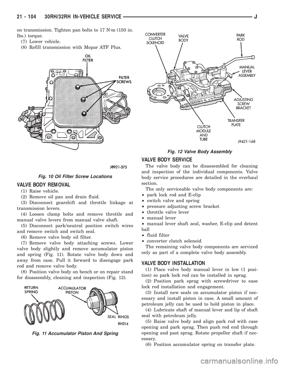
and spring (Fig. 11). Rotate valve body down and
away from case. Pull it forward to disengage park
rod and remove valve body.
(8) Position valve body on bench or on repair stand
for disassembly, cleaning and inspection (Fig. 12).
VALVE BODY SERVICE
The valve body can be disassembled for cleaning
and inspection of the individual components. Valve
body service procedures are detailed in the overhaul
section.
The only serviceable valve body components are:
²park lock rod and E-clip
²switch valve and spring
²pressure adjusting screw bracket
²throttle valve lever
²manual lever
²manual lever shaft seal, washer, E-clip and detent
ball
²fluid filter
²converter clutch solenoid
The remaining valve body components are serviced
only as part of a complete valve body assembly.
VALVE BODY INSTALLATION
(1) Place valve body manual lever in low (1 posi-
tion) so park lock rod can be installed in sprag.
(2) Position park sprag with screwdriver to ease
lock rod installation and engagement.
(3) Install new seals on accumulator piston if nec-
essary and install piston in case. A small amount of
petroleum jelly can be used to hold piston in place.
(4) Lubricate shaft of manual lever and lip of shaft
seal with petroleum jelly.
(5) Raise valve body and align park rod with case
opening and park sprag. Then push rod end through
opening and past sprag. Rotate propeller shaft if nec-
essary.
(6) Position accumulator spring on transfer plate.
Fig. 10 Oil Filter Screw Locations
Fig. 11 Accumulator Piston And Spring
Fig. 12 Valve Body Assembly
21 - 104 30RH/32RH IN-VEHICLE SERVICEJ
Page 1671 of 2158
Inspection
Check the sprag shaft for scores and for free move-
ment in the housing and sprag.
Check the sprag and control rod springs for loss of
tension or distortion. Check the square lug on the
sprag for broken edges. Check the lugs on the gover-
nor support (park gear) for broken edges. Replace
any park lock components that are worn or damaged.
Check the knob on the end of the control rod for
nicks, burrs and free turning. Replace the rod if the
knob is grooved, or worn, or if the rod is bent. The
park lock rods used in Chrysler 3-speed transmis-
sions are different lengths. If the rod must be re-
placed, be sure to install the correct length and
shape rod.
COMPONENT INSTALLATION
(1) Install park lock rod on valve body.
(2) Install reaction plug and pin assembly in the
housing and install the snap ring.
(3) Position sprag and spring in housing and in-
stall sprag shaft. Be sure square lug on sprag is fac-
ing park gear and that spring is positioned so it
moves sprag away from park gear.
(4) Install valve body.
(5) Install adapter housing and transfer case.
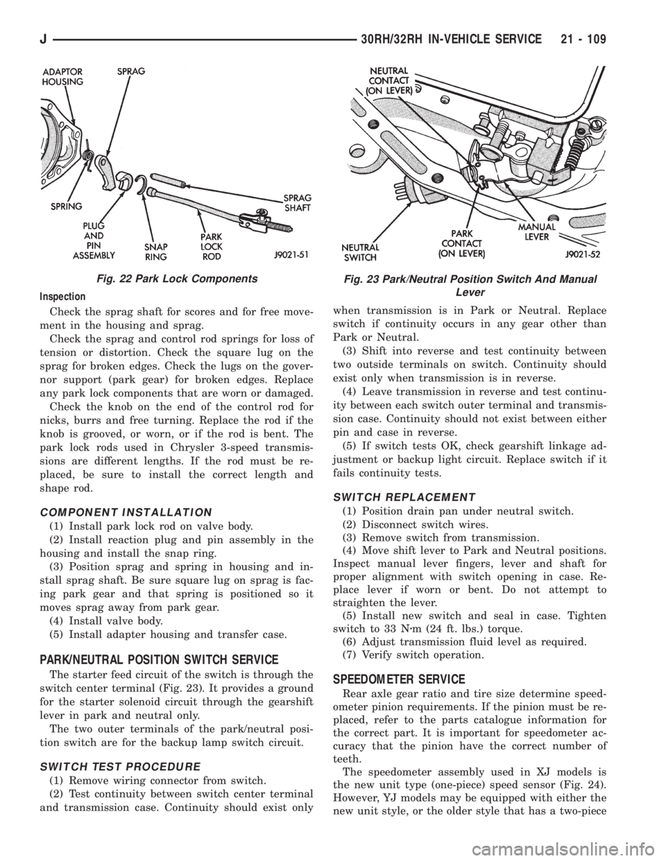
PARK/NEUTRAL POSITION SWITCH SERVICE
The starter feed circuit of the switch is through the
switch center terminal (Fig. 23). It provides a ground
for the starter solenoid circuit through the gearshift
lever in park and neutral only.
The two outer terminals of the park/neutral posi-
tion switch are for the backup lamp switch circuit.
SWITCH TEST PROCEDURE
(1) Remove wiring connector from switch.
(2) Test continuity between switch center terminal
and transmission case. Continuity should exist onlywhen transmission is in Park or Neutral. Replace
switch if continuity occurs in any gear other than
Park or Neutral.
(3) Shift into reverse and test continuity between
two outside terminals on switch. Continuity should
exist only when transmission is in reverse.
(4) Leave transmission in reverse and test continu-
ity between each switch outer terminal and transmis-
sion case. Continuity should not exist between either
pin and case in reverse.
(5) If switch tests OK, check gearshift linkage ad-
justment or backup light circuit. Replace switch if it
fails continuity tests.
SWITCH REPLACEMENT
(1) Position drain pan under neutral switch.
(2) Disconnect switch wires.
(3) Remove switch from transmission.
(4) Move shift lever to Park and Neutral positions.
Inspect manual lever fingers, lever and shaft for
proper alignment with switch opening in case. Re-
place lever if worn or bent. Do not attempt to
straighten the lever.
(5) Install new switch and seal in case. Tighten
switch to 33 Nzm (24 ft. lbs.) torque.
(6) Adjust transmission fluid level as required.
(7) Verify switch operation.
SPEEDOMETER SERVICE
Rear axle gear ratio and tire size determine speed-
ometer pinion requirements. If the pinion must be re-
placed, refer to the parts catalogue information for
the correct part. It is important for speedometer ac-
curacy that the pinion have the correct number of
teeth.
The speedometer assembly used in XJ models is
the new unit type (one-piece) speed sensor (Fig. 24).
However, YJ models may be equipped with either the
new unit style, or the older style that has a two-piece
Fig. 22 Park Lock ComponentsFig. 23 Park/Neutral Position Switch And Manual
Lever
J30RH/32RH IN-VEHICLE SERVICE 21 - 109
Page 1675 of 2158
CONNECTING COOLER LINES AND FITTINGS
(ALL TYPES)
(1) Wipe cooler line and fitting clean with shop
towel.
(2) Insert cooler line into fitting. Then push line
inward until retainer or insert secures line. A snap or
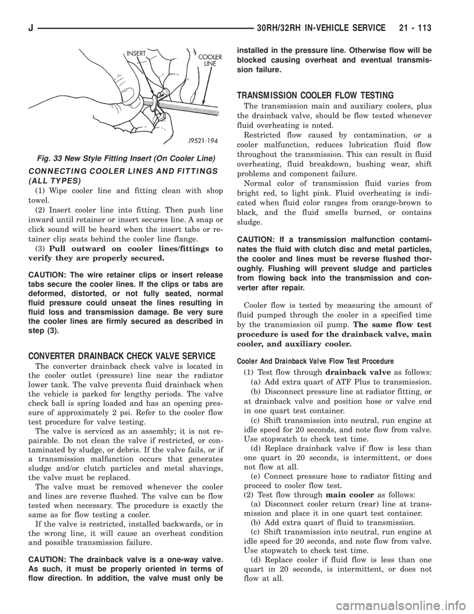
click sound will be heard when the insert tabs or re-
tainer clip seats behind the cooler line flange.
(3)Pull outward on cooler lines/fittings to
verify they are properly secured.
CAUTION: The wire retainer clips or insert release
tabs secure the cooler lines. If the clips or tabs are
deformed, distorted, or not fully seated, normal
fluid pressure could unseat the lines resulting in
fluid loss and transmission damage. Be very sure
the cooler lines are firmly secured as described in
step (3).
CONVERTER DRAINBACK CHECK VALVE SERVICE
The converter drainback check valve is located in
the cooler outlet (pressure) line near the radiator
lower tank. The valve prevents fluid drainback when
the vehicle is parked for lengthy periods. The valve
check ball is spring loaded and has an opening pres-
sure of approximately 2 psi. Refer to the cooler flow
test procedure for valve testing.
The valve is serviced as an assembly; it is not re-
pairable. Do not clean the valve if restricted, or con-
taminated by sludge, or debris. If the valve fails, or if
a transmission malfunction occurs that generates
sludge and/or clutch particles and metal shavings,
the valve must be replaced.
The valve must be removed whenever the cooler
and lines are reverse flushed. The valve can be flow
tested when necessary. The procedure is exactly the
same as for flow testing a cooler.
If the valve is restricted, installed backwards, or in
the wrong line, it will cause an overheat condition
and possible transmission failure.
CAUTION: The drainback valve is a one-way valve.
As such, it must be properly oriented in terms of
flow direction. In addition, the valve must only beinstalled in the pressure line. Otherwise flow will be
blocked causing overheat and eventual transmis-
sion failure.
TRANSMISSION COOLER FLOW TESTING
The transmission main and auxiliary coolers, plus
the drainback valve, should be flow tested whenever
fluid overheating is noted.
Restricted flow caused by contamination, or a
cooler malfunction, reduces lubrication fluid flow
throughout the transmission. This can result in fluid
overheating, fluid breakdown, bushing wear, shift
problems and component failure.
Normal color of transmission fluid varies from
bright red, to light pink. Fluid overheating is indi-
cated when fluid color ranges from orange-brown to
black, and the fluid smells burned, or contains
sludge.
CAUTION: If a transmission malfunction contami-
nates the fluid with clutch disc and metal particles,
the cooler and lines must be reverse flushed thor-
oughly. Flushing will prevent sludge and particles
from flowing back into the transmission and con-
verter after repair.
Cooler flow is tested by measuring the amount of
fluid pumped through the cooler in a specified time
by the transmission oil pump.The same flow test
procedure is used for the drainback valve, main
cooler, and auxiliary cooler.
Cooler And Drainback Valve Flow Test Procedure
(1) Test flow throughdrainback valveas follows:
(a) Add extra quart of ATF Plus to transmission.
(b) Disconnect pressure line at radiator fitting, or
at drainback valve and position hose or valve end
in one quart test container.
(c) Shift transmission into neutral, run engine at
idle speed for 20 seconds, and note flow from valve.
Use stopwatch to check test time.
(d) Replace drainback valve if flow is less than
one quart in 20 seconds, is intermittent, or does
not flow at all.
(e) Connect pressure hose to radiator fitting and
proceed to cooler flow test.
(2) Test flow throughmain cooleras follows:
(a) Disconnect cooler return (rear) line at trans-
mission and place it in one quart test container.
(b) Add extra quart of fluid to transmission.
(c) Shift transmission into neutral, run engine at
idle speed for 20 seconds, and note flow from valve.
Use stopwatch to check test time.
(d) Replace cooler if fluid flow is less than one
quart in 20 seconds, is intermittent, or does not
flow at all.
Fig. 33 New Style Fitting Insert (On Cooler Line)
J30RH/32RH IN-VEHICLE SERVICE 21 - 113
Page 1678 of 2158
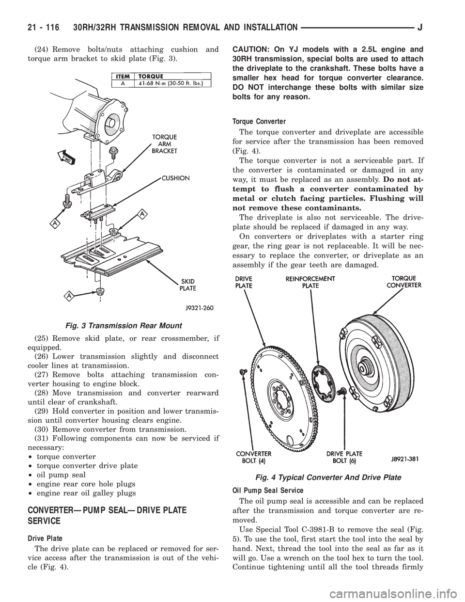
(24) Remove bolts/nuts attaching cushion and
torque arm bracket to skid plate (Fig. 3).
(25) Remove skid plate, or rear crossmember, if
equipped.
(26) Lower transmission slightly and disconnect
cooler lines at transmission.
(27) Remove bolts attaching transmission con-
verter housing to engine block.
(28) Move transmission and converter rearward
until clear of crankshaft.
(29) Hold converter in position and lower transmis-
sion until converter housing clears engine.
(30) Remove converter from transmission.
(31) Following components can now be serviced if
necessary:
²torque converter
²torque converter drive plate
²oil pump seal
²engine rear core hole plugs
²engine rear oil galley plugs
CONVERTERÐPUMP SEALÐDRIVE PLATE
SERVICE
Drive Plate
The drive plate can be replaced or removed for ser-
vice access after the transmission is out of the vehi-
cle (Fig. 4).CAUTION: On YJ models with a 2.5L engine and
30RH transmission, special bolts are used to attach
the driveplate to the crankshaft. These bolts have a
smaller hex head for torque converter clearance.
DO NOT interchange these bolts with similar size
bolts for any reason.
Torque Converter
The torque converter and driveplate are accessible
for service after the transmission has been removed
(Fig. 4).
The torque converter is not a serviceable part. If
the converter is contaminated or damaged in any
way, it must be replaced as an assembly.Do not at-
tempt to flush a converter contaminated by
metal or clutch facing particles. Flushing will
not remove these contaminants.
The driveplate is also not serviceable. The drive-
plate should be replaced if damaged in any way.
On converters or driveplates with a starter ring
gear, the ring gear is not replaceable. It will be nec-
essary to replace the converter, or driveplate as an
assembly if the gear teeth are damaged.
Oil Pump Seal Service
The oil pump seal is accessible and can be replaced
after the transmission and torque converter are re-
moved.
Use Special Tool C-3981-B to remove the seal (Fig.
5). To use the tool, first start the tool into the seal by
hand. Next, thread the tool into the seal as far as it
will go. Use a wrench on the tool hex to turn the tool.
Continue tightening until all the tool threads firmly
Fig. 3 Transmission Rear Mount
Fig. 4 Typical Converter And Drive Plate
21 - 116 30RH/32RH TRANSMISSION REMOVAL AND INSTALLATIONJ
Page 1695 of 2158
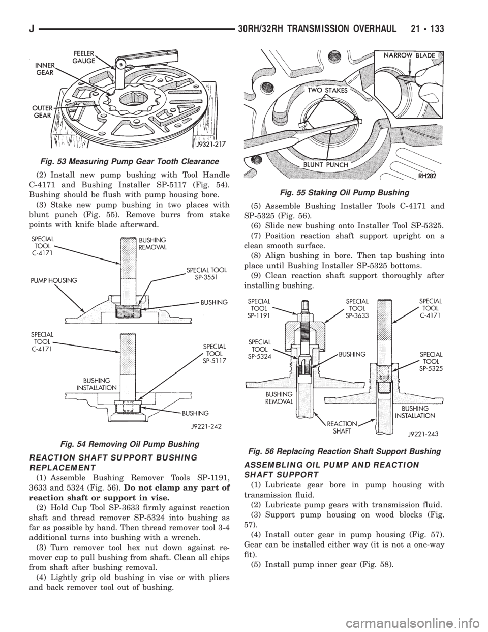
(2) Install new pump bushing with Tool Handle
C-4171 and Bushing Installer SP-5117 (Fig. 54).
Bushing should be flush with pump housing bore.
(3) Stake new pump bushing in two places with
blunt punch (Fig. 55). Remove burrs from stake
points with knife blade afterward.
REACTION SHAFT SUPPORT BUSHING
REPLACEMENT
(1) Assemble Bushing Remover Tools SP-1191,
3633 and 5324 (Fig. 56).Do not clamp any part of
reaction shaft or support in vise.
(2) Hold Cup Tool SP-3633 firmly against reaction
shaft and thread remover SP-5324 into bushing as
far as possible by hand. Then thread remover tool 3-4
additional turns into bushing with a wrench.
(3) Turn remover tool hex nut down against re-
mover cup to pull bushing from shaft. Clean all chips
from shaft after bushing removal.
(4) Lightly grip old bushing in vise or with pliers
and back remover tool out of bushing.(5) Assemble Bushing Installer Tools C-4171 and
SP-5325 (Fig. 56).
(6) Slide new bushing onto Installer Tool SP-5325.
(7) Position reaction shaft support upright on a
clean smooth surface.
(8) Align bushing in bore. Then tap bushing into
place until Bushing Installer SP-5325 bottoms.
(9) Clean reaction shaft support thoroughly after
installing bushing.
ASSEMBLING OIL PUMP AND REACTION
SHAFT SUPPORT
(1) Lubricate gear bore in pump housing with
transmission fluid.
(2) Lubricate pump gears with transmission fluid.
(3) Support pump housing on wood blocks (Fig.
57).
(4) Install outer gear in pump housing (Fig. 57).
Gear can be installed either way (it is not a one-way
fit).
(5) Install pump inner gear (Fig. 58).
Fig. 53 Measuring Pump Gear Tooth Clearance
Fig. 54 Removing Oil Pump Bushing
Fig. 55 Staking Oil Pump Bushing
Fig. 56 Replacing Reaction Shaft Support Bushing
J30RH/32RH TRANSMISSION OVERHAUL 21 - 133
Page 1698 of 2158
Replace the clutch discs if warped, worn, scored,
burned or charred, or if the facing is flaking off. Re-
place the steel plates if heavily scored, warped, or
broken. Be sure the driving lugs on the plates are in
good condition. The lugs must not be bent, cracked or
damaged in any way.
Replace the clutch spring and spring retainer if ei-
ther is distorted, warped or broken.
Check the lug grooves in the clutch retainer. The
steel plates should slide freely in the slots. Replace
the retainer if the grooves are worn or damaged.
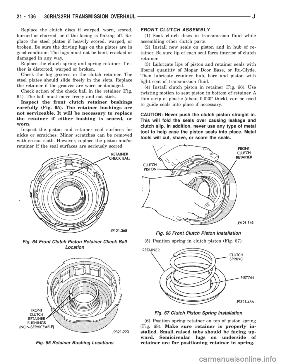
Check action of the check ball in the retainer (Fig.
64). The ball must move freely and not stick.
Inspect the front clutch retainer bushings
carefully (Fig. 65). The retainer bushings are
not serviceable. It will be necessary to replace
the retainer if either bushing is scored, or
worn.
Inspect the piston and retainer seal surfaces for
nicks or scratches. Minor scratches can be removed
with crocus cloth. However, replace the piston and/or
retainer if the seal surfaces are seriously scored.FRONT CLUTCH ASSEMBLY
(1) Soak clutch discs in transmission fluid while
assembling other clutch parts.
(2) Install new seals on piston and in hub of re-
tainer. Be sure lip of each seal faces interior of clutch
retainer.
(3) Lubricate lips of piston and retainer seals with
liberal quantity of Mopar Door Ease, or Ru-Glyde.
Then lubricate retainer hub, bore and piston with
light coat of transmission fluid.
(4) Install clutch piston in retainer (Fig. 66). Use
twisting motion to seat piston in bottom of retainer. A
thin strip of plastic (about 0.0209thick), can be used
to guide seals into place if necessary.
CAUTION: Never push the clutch piston straight in.
This will fold the seals over causing leakage and
clutch slip. In addition, never use any type of metal
tool to help ease the piston seals into place. Metal
tools will cut, shave, or score the seals.
(5) Position spring in clutch piston (Fig. 67).
(6) Position spring retainer on top of piston spring
(Fig. 68).Make sure retainer is properly in-
stalled. Small raised tabs should be facing up-
ward. Semicircular lugs on underside of
retainer are for positioning retainer in spring.
Fig. 64 Front Clutch Piston Retainer Check Ball
Location
Fig. 65 Retainer Bushing Locations
Fig. 66 Front Clutch Piston Installation
Fig. 67 Clutch Piston Spring Installation
21 - 136 30RH/32RH TRANSMISSION OVERHAULJ
Page 1701 of 2158
Replace the retainer bushing if worn, scored, or
doubt exists about bushing condition.
Inspect the piston and retainer seal surfaces for
nicks or scratches. Minor scratches can be removed
with crocus cloth. However, replace the piston and/or
retainer if the seal surfaces are seriously scored.
Check condition of the fiber thrust washer and
metal output shaft thrust washer. Replace either
washer if worn or damaged.
Check condition of the seal rings on the input shaft
and clutch retainer hub. Replace the seal rings only
if worn, distorted, or damaged. The input shaft front
seal ring is teflon with chamfered ends. The rear ring
is metal with interlocking ends.
Check the input shaft for wear, or damage. Replace
the shaft if worn, scored or damaged in any way.
ASSEMBLING REAR CLUTCH
(1) Soak clutch discs in transmission fluid while
assembling other clutch parts.
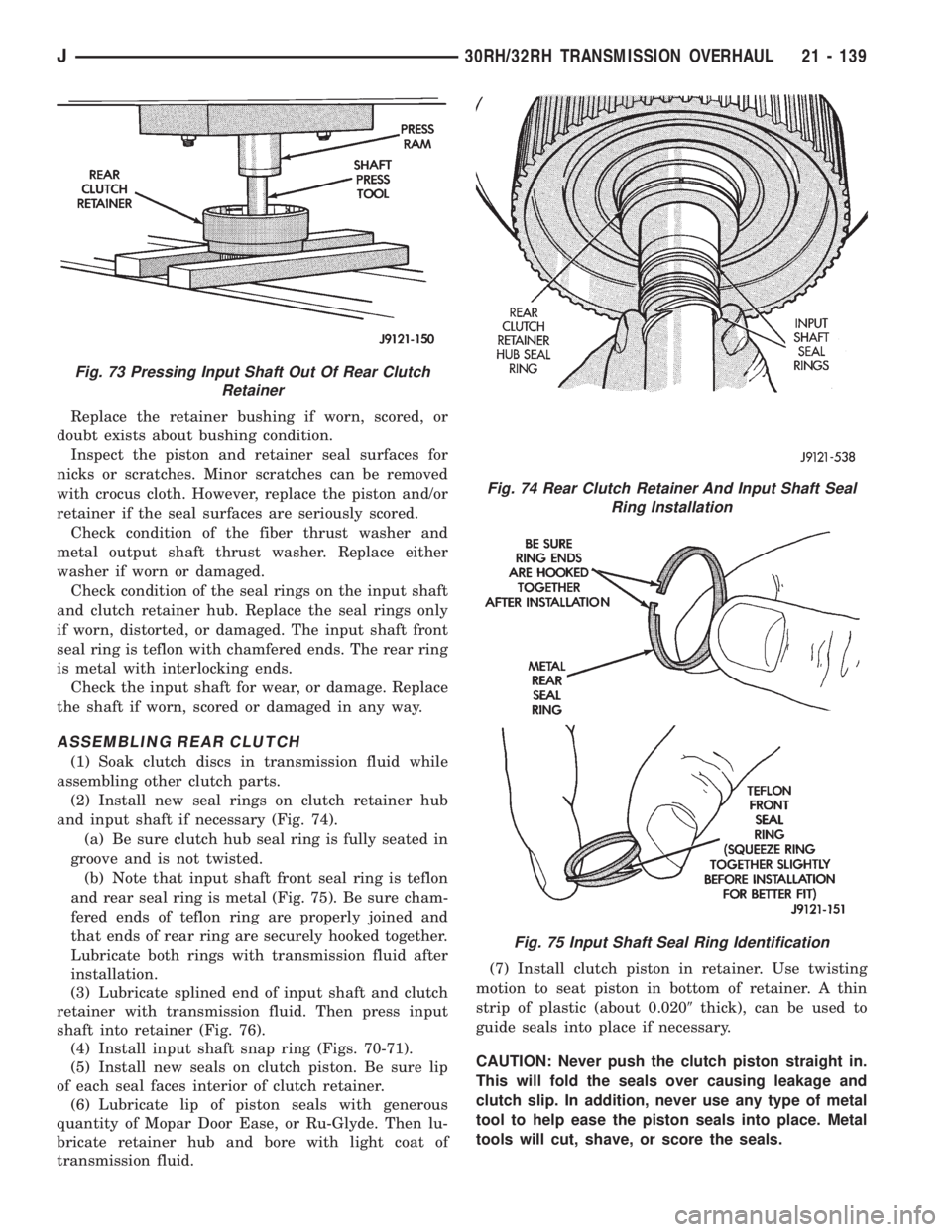
(2) Install new seal rings on clutch retainer hub
and input shaft if necessary (Fig. 74).
(a) Be sure clutch hub seal ring is fully seated in
groove and is not twisted.
(b) Note that input shaft front seal ring is teflon
and rear seal ring is metal (Fig. 75). Be sure cham-
fered ends of teflon ring are properly joined and
that ends of rear ring are securely hooked together.
Lubricate both rings with transmission fluid after
installation.
(3) Lubricate splined end of input shaft and clutch
retainer with transmission fluid. Then press input
shaft into retainer (Fig. 76).
(4) Install input shaft snap ring (Figs. 70-71).
(5) Install new seals on clutch piston. Be sure lip
of each seal faces interior of clutch retainer.
(6) Lubricate lip of piston seals with generous
quantity of Mopar Door Ease, or Ru-Glyde. Then lu-
bricate retainer hub and bore with light coat of
transmission fluid.(7) Install clutch piston in retainer. Use twisting
motion to seat piston in bottom of retainer. A thin
strip of plastic (about 0.0209thick), can be used to
guide seals into place if necessary.
CAUTION: Never push the clutch piston straight in.
This will fold the seals over causing leakage and
clutch slip. In addition, never use any type of metal
tool to help ease the piston seals into place. Metal
tools will cut, shave, or score the seals.
Fig. 73 Pressing Input Shaft Out Of Rear Clutch
Retainer
Fig. 74 Rear Clutch Retainer And Input Shaft Seal
Ring Installation
Fig. 75 Input Shaft Seal Ring Identification
J30RH/32RH TRANSMISSION OVERHAUL 21 - 139