1995 JEEP YJ light
[x] Cancel search: lightPage 1865 of 2158
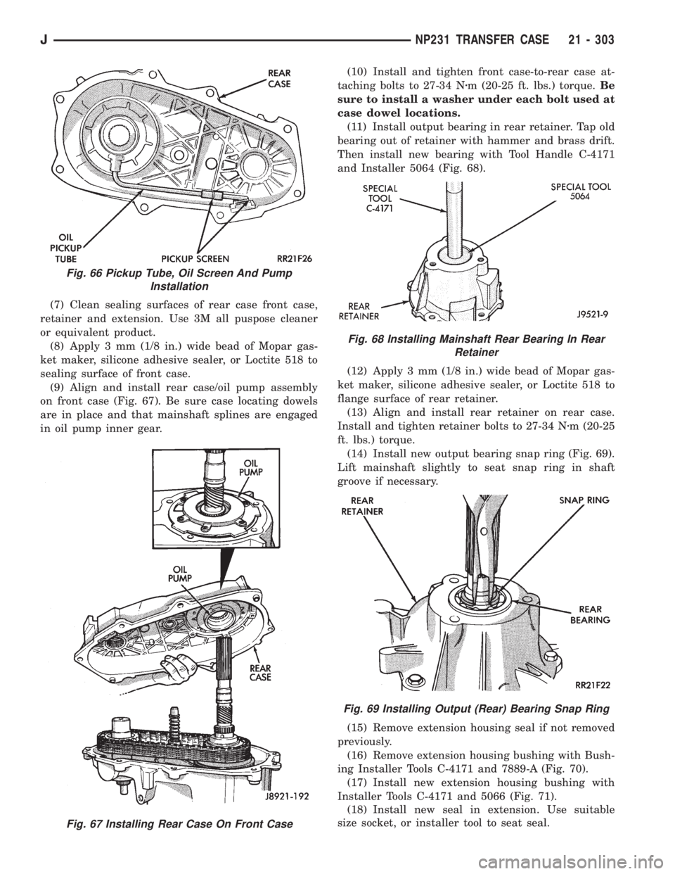
(7) Clean sealing surfaces of rear case front case,
retainer and extension. Use 3M all puspose cleaner
or equivalent product.
(8) Apply 3 mm (1/8 in.) wide bead of Mopar gas-
ket maker, silicone adhesive sealer, or Loctite 518 to
sealing surface of front case.
(9) Align and install rear case/oil pump assembly
on front case (Fig. 67). Be sure case locating dowels
are in place and that mainshaft splines are engaged
in oil pump inner gear.(10) Install and tighten front case-to-rear case at-
taching bolts to 27-34 Nzm (20-25 ft. lbs.) torque.Be
sure to install a washer under each bolt used at
case dowel locations.
(11) Install output bearing in rear retainer. Tap old
bearing out of retainer with hammer and brass drift.
Then install new bearing with Tool Handle C-4171
and Installer 5064 (Fig. 68).
(12) Apply 3 mm (1/8 in.) wide bead of Mopar gas-
ket maker, silicone adhesive sealer, or Loctite 518 to
flange surface of rear retainer.
(13) Align and install rear retainer on rear case.
Install and tighten retainer bolts to 27-34 Nzm (20-25
ft. lbs.) torque.
(14) Install new output bearing snap ring (Fig. 69).
Lift mainshaft slightly to seat snap ring in shaft
groove if necessary.
(15) Remove extension housing seal if not removed
previously.
(16) Remove extension housing bushing with Bush-
ing Installer Tools C-4171 and 7889-A (Fig. 70).
(17) Install new extension housing bushing with
Installer Tools C-4171 and 5066 (Fig. 71).
(18) Install new seal in extension. Use suitable
size socket, or installer tool to seat seal.
Fig. 67 Installing Rear Case On Front Case
Fig. 66 Pickup Tube, Oil Screen And Pump
Installation
Fig. 68 Installing Mainshaft Rear Bearing In Rear
Retainer
Fig. 69 Installing Output (Rear) Bearing Snap Ring
JNP231 TRANSFER CASE 21 - 303
Page 1888 of 2158
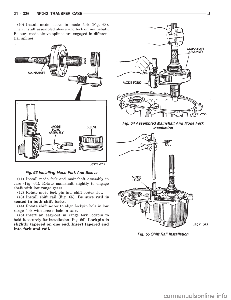
(40) Install mode sleeve in mode fork (Fig. 63).
Then install assembled sleeve and fork on mainshaft.
Be sure mode sleeve splines are engaged in differen-
tial splines.
(41) Install mode fork and mainshaft assembly in
case (Fig. 64). Rotate mainshaft slightly to engage
shaft with low range gears.
(42) Rotate mode fork pin into shift sector slot.
(43) Install shift rail (Fig. 65).Be sure rail is
seated in both shift forks.
(44) Rotate shift sector to align lockpin hole in low
range fork with access hole in case.
(45) Insert an easy-out in range fork lockpin to
hold it securely for installation (Fig. 66).Lockpin is
slightly tapered on one end. Insert tapered end
into fork and rail.
Fig. 63 Installing Mode Fork And Sleeve
Fig. 64 Assembled Mainshaft And Mode Fork
Installation
Fig. 65 Shift Rail Installation
21 - 326 NP242 TRANSFER CASEJ
Page 1891 of 2158
(62) Install and tighten front case-to-rear case
bolts to 41 Nzm (30 ft. lbs.) torque.Be sure to in-
stall a washer under each bolt used at case
dowel locations.
(63) Tap rear retainer bearing out of retainer with
hammer and brass drift.
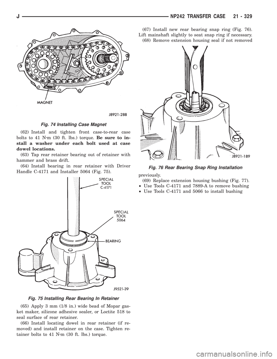
(64) Install bearing in rear retainer with Driver
Handle C-4171 and Installer 5064 (Fig. 75).
(65) Apply 3 mm (1/8 in.) wide bead of Mopar gas-
ket maker, silicone adhesive sealer, or Loctite 518 to
seal surface of rear retainer.
(66) Install locating dowel in rear retainer (if re-
moved) and install retainer on the case. Tighten re-
tainer bolts to 41 Nzm (30 ft. lbs.) torque.(67) Install new rear bearing snap ring (Fig. 76).
Lift mainshaft slightly to seat snap ring if necessary.
(68) Remove extension housing seal if not removed
previously.
(69) Replace extension housing bushing (Fig. 77).
²Use Tools C-4171 and 7889-A to remove bushing
²Use Tools C-4171 and 5066 to install bushing
Fig. 74 Installing Case Magnet
Fig. 75 Installing Rear Bearing In Retainer
Fig. 76 Rear Bearing Snap Ring Installation
JNP242 TRANSFER CASE 21 - 329
Page 1907 of 2158
WHEELS AND TIRES
CONTENTS
page page
SPECIFICATIONS........................ 12
TIRES.................................. 1VEHICLE VIBRATION..................... 10
WHEELS................................ 6
TIRES
INDEX
page page
Cleaning of Tires.......................... 2
General Information........................ 1
Pressure Gauges.......................... 2
Repairing Leaks........................... 3
Replacement Tires......................... 2Rotation................................. 3
Tire Inflation Pressures...................... 2
Tire Noise or Vibration...................... 4
Tire Wear Patterns......................... 4
Tread Wear Indicators....................... 3
GENERAL INFORMATION
Tires are designed for each specific vehicle. They
provide the best overall performance for normal oper-
ation. The ride and handling characteristics match
the vehicle's requirements. With proper care they
will give excellent reliability, traction, skid resis-
tance, and tread life. These tires have specific load
carrying capacities. When correctly inflated, they will
operate properly.
Tires used in cool climates, and with light loads
will have a longer life than tires used in hot climates
with heavy loads. Abrasive road surfaces will acceler-
ate tire wear.
Driving habits have more effect on tire life than
any other factor. Careful drivers will obtain much
greater mileage than careless drivers.
Driving habits that shorten the life of any tire;
²Rapid acceleration and deceleration
²Severe application of brakes
²High-speed driving
²Taking turns at excessive speeds
²Striking curbs and other obstacles
It is very important to follow the tire rotation in-
terval
IDENTIFICATION
Tire type, size, aspect ratio and speed rating are
encoded in the letters and numbers imprinted on the
side wall of the tire. Refer to the chart to decipher
the tire identification code (Fig. 1).Performance tires will have a speed rating letter
after the aspect ratio number. The speed rating is not
always printed on the tire sidewall. The letterSin-
dicates that the tire is speed rated up to 112 mph.
²Qup to 100 mph
²Tup to 118 mph
²Uup to 124 mph
²Hup to 130 mph
²Vup to 149 mph
²Zmore than 149 mph (consult the tire manufac-
turer for the specific speed rating)
An All Season type tire will have eitherM+S,M
&SorMÐS(indicating mud and snow traction) im-
printed on the side wall.
RADIAL-PLY TIRES
Radial-ply tires improve handling, tread life, ride
quality and decrease rolling resistance.
Radial-ply tires must always be used in sets of
four. Under no circumstances should they be used on
the front only. They may be mixed with temporary
spare tires when necessary, but reduced speeds are
recommended.
Radial-ply tires have the same load-carrying capac-
ity as other types of tires of the same size. They use
the same recommended inflation pressures.
SPARE TIRE (TEMPORARY)
The compact spare tire is designed for emergency
use only. The original tire should be repaired and re-
installed at the first opportunity. Refer to Owner's
Manual for complete details.
JWHEELS AND TIRES 22 - 1
Page 1935 of 2158
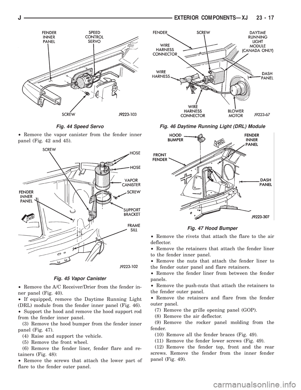
²Remove the vapor canister from the fender inner
panel (Fig. 42 and 45).
²Remove the A/C Receiver/Drier from the fender in-
ner panel (Fig. 40).
²If equipped, remove the Daytime Running Light
(DRL) module from the fender inner panel (Fig. 46).
²Support the hood and remove the hood support rod
from the fender inner panel.
(3) Remove the hood bumper from the fender inner
panel (Fig. 47).
(4) Raise and support the vehicle.
(5) Remove the front wheel.
(6) Remove the fender liner, fender flare and re-
tainers (Fig. 48):
²Remove the screws that attach the lower part of
flare to the fender outer panel.²Remove the rivets that attach the flare to the air
deflector.
²Remove the retainers that attach the fender liner
to the fender inner panel.
²Remove the nuts that attach the fender liner to
the fender outer panel and flare retainers.
²Remove the fender liner from between the fender
panels.
²Remove the push-nuts that attach the retainers to
the fender outer panel.
²Remove the retainers and flare from the fender
outer panel.
(7) Remove the grille opening panel (GOP).
(8) Remove the air deflector.
(9) Remove the rocker panel molding from the
fender.
(10) Remove all the fender braces (Fig. 49).
(11) Remove the fender lower screws (Fig. 49).
(12) Remove the fender top, front and the rear
screws. Remove the fender from the inner fender
panel (Fig. 49).
Fig. 44 Speed Servo
Fig. 45 Vapor Canister
Fig. 46 Daytime Running Light (DRL) Module
Fig. 47 Hood Bumper
JEXTERIOR COMPONENTSÐXJ 23 - 17
Page 1937 of 2158
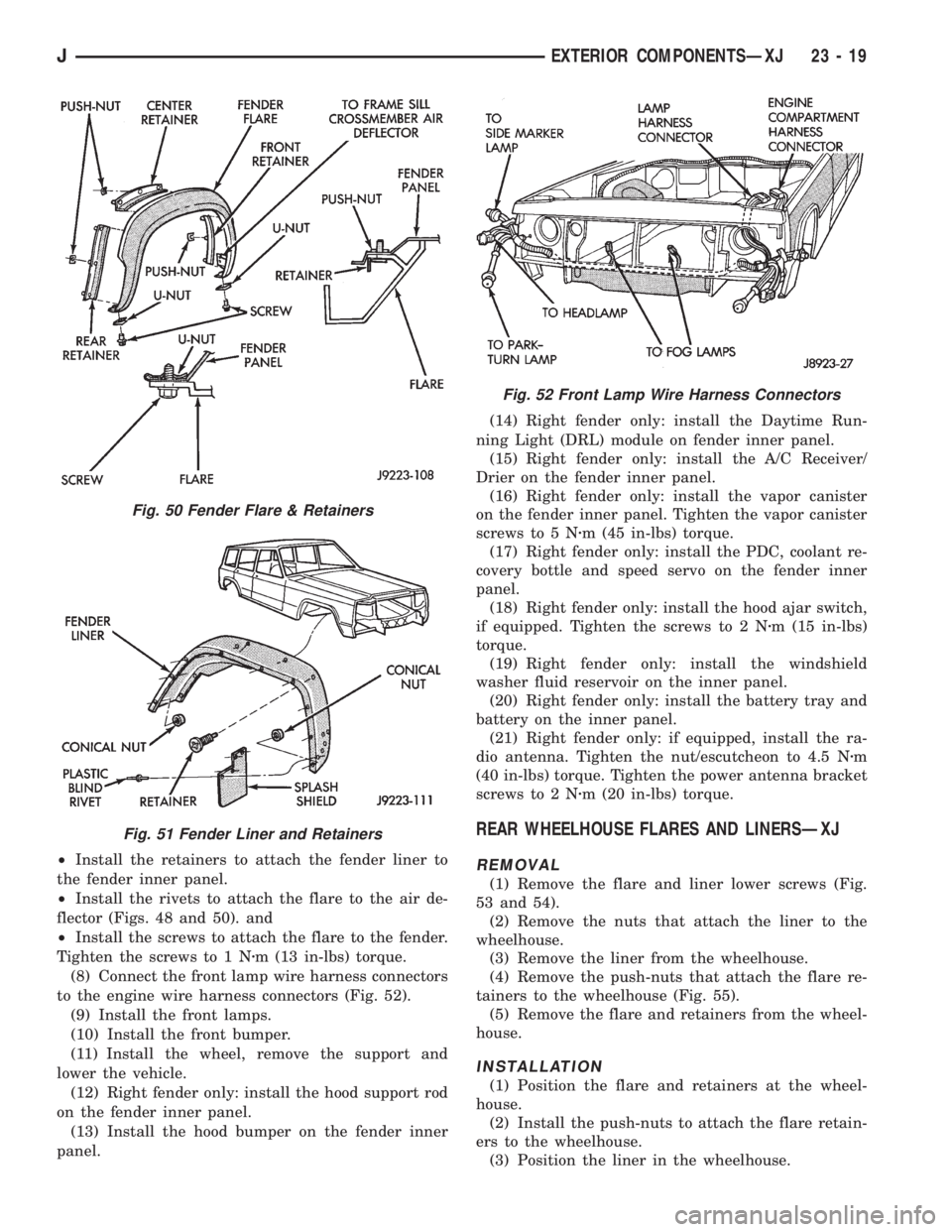
²Install the retainers to attach the fender liner to
the fender inner panel.
²Install the rivets to attach the flare to the air de-
flector (Figs. 48 and 50). and
²Install the screws to attach the flare to the fender.
Tighten the screws to 1 Nzm (13 in-lbs) torque.
(8) Connect the front lamp wire harness connectors
to the engine wire harness connectors (Fig. 52).
(9) Install the front lamps.
(10) Install the front bumper.
(11) Install the wheel, remove the support and
lower the vehicle.
(12) Right fender only: install the hood support rod
on the fender inner panel.
(13) Install the hood bumper on the fender inner
panel.(14) Right fender only: install the Daytime Run-
ning Light (DRL) module on fender inner panel.
(15) Right fender only: install the A/C Receiver/
Drier on the fender inner panel.
(16) Right fender only: install the vapor canister
on the fender inner panel. Tighten the vapor canister
screws to 5 Nzm (45 in-lbs) torque.
(17) Right fender only: install the PDC, coolant re-
covery bottle and speed servo on the fender inner
panel.
(18) Right fender only: install the hood ajar switch,
if equipped. Tighten the screws to 2 Nzm (15 in-lbs)
torque.
(19) Right fender only: install the windshield
washer fluid reservoir on the inner panel.
(20) Right fender only: install the battery tray and
battery on the inner panel.
(21) Right fender only: if equipped, install the ra-
dio antenna. Tighten the nut/escutcheon to 4.5 Nzm
(40 in-lbs) torque. Tighten the power antenna bracket
screws to 2 Nzm (20 in-lbs) torque.
REAR WHEELHOUSE FLARES AND LINERSÐXJ
REMOVAL
(1) Remove the flare and liner lower screws (Fig.
53 and 54).
(2) Remove the nuts that attach the liner to the
wheelhouse.
(3) Remove the liner from the wheelhouse.
(4) Remove the push-nuts that attach the flare re-
tainers to the wheelhouse (Fig. 55).
(5) Remove the flare and retainers from the wheel-
house.
INSTALLATION
(1) Position the flare and retainers at the wheel-
house.
(2) Install the push-nuts to attach the flare retain-
ers to the wheelhouse.
(3) Position the liner in the wheelhouse.
Fig. 50 Fender Flare & Retainers
Fig. 51 Fender Liner and Retainers
Fig. 52 Front Lamp Wire Harness Connectors
JEXTERIOR COMPONENTSÐXJ 23 - 19
Page 1941 of 2158
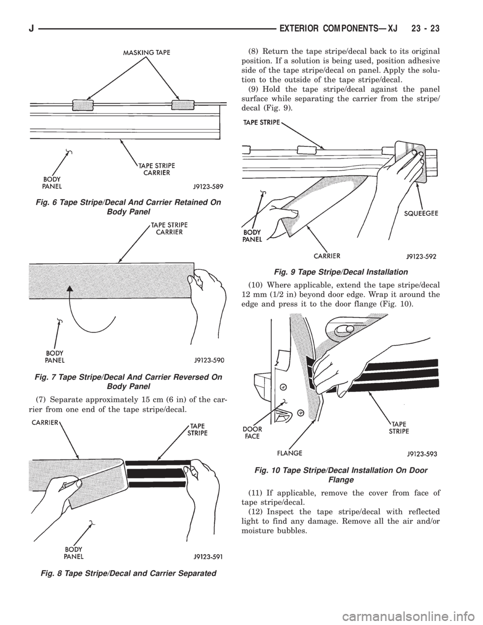
(7) Separate approximately 15 cm (6 in) of the car-
rier from one end of the tape stripe/decal.(8) Return the tape stripe/decal back to its original
position. If a solution is being used, position adhesive
side of the tape stripe/decal on panel. Apply the solu-
tion to the outside of the tape stripe/decal.
(9) Hold the tape stripe/decal against the panel
surface while separating the carrier from the stripe/
decal (Fig. 9).
(10) Where applicable, extend the tape stripe/decal
12 mm (1/2 in) beyond door edge. Wrap it around the
edge and press it to the door flange (Fig. 10).
(11) If applicable, remove the cover from face of
tape stripe/decal.
(12) Inspect the tape stripe/decal with reflected
light to find any damage. Remove all the air and/or
moisture bubbles.
Fig. 6 Tape Stripe/Decal And Carrier Retained On
Body Panel
Fig. 7 Tape Stripe/Decal And Carrier Reversed On
Body Panel
Fig. 8 Tape Stripe/Decal and Carrier Separated
Fig. 9 Tape Stripe/Decal Installation
Fig. 10 Tape Stripe/Decal Installation On Door
Flange
JEXTERIOR COMPONENTSÐXJ 23 - 23
Page 1943 of 2158
(3) Retain the tape stripe/decal firmly against flat
surface and separate the carrier from tape stripe/de-
cal.
(4) Use a sponge and apply solution to the tape
stripe/decal adhesive and to panel surface.
(5) Position the adhesive side of tape stripe/decal
on the panel with the bottom aligned with the char-
acter line.
²Align the end of the replacement tape stripe/decal
with the end of existing tape stripe/decal.
²Correctly align the index darts and index notches.
(6) If a complete replacement tape stripe/decal is
not being installed:
²Position the replacement tape stripe/decal section
at the center of the repair area.
²Align it with the existing tape stripe/decal.
²Allow at least 12 mm (1/2 in) of the tape stripe/de-
cal section to overlap the tape stripe/decal edges.
(7) Apply the wetting solution to the outer side of
the tape stripe/decal.
CAUTION: Avoid unnecessary pulling and stretch-
ing at the ends.
(8) Slide a squeegee from the center to the ends of
the tape stripe/decal. Use firm strokes to remove all
of the air bubbles.
(9) If a wrinkle is trapped in the tape stripe/decal
stop immediately. Lift the wrinkled area and re-align
it with the character line to remove the wrinkle.Do
not lift the tape stripe/decal if only a few air
bubbles exist.
(10) Where applicable, allow 12 mm (1/2 in) extra
tape stripe/decal to extend beyond edges.
(11) Fold the excess tape onto the inside flange and
adhere it with finger pressure.
(12) Inspect the tape stripe/decal installation with
the reflected light to find any damage.
(13) Remove all the air and moisture bubbles from
the tape stripe/decal with a needle or pin.
(14) Install any removed components and clean the
vehicle as necessary.
QUARTER WINDOW APPLIQUEÐXJ
REMOVAL/INSTALLATION
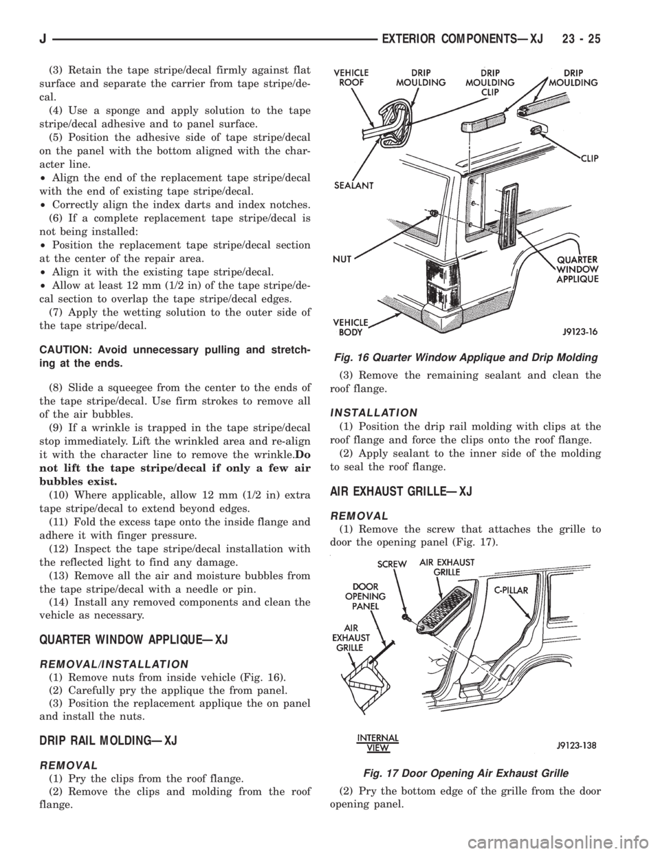
(1) Remove nuts from inside vehicle (Fig. 16).
(2) Carefully pry the applique the from panel.
(3) Position the replacement applique the on panel
and install the nuts.
DRIP RAIL MOLDINGÐXJ
REMOVAL
(1) Pry the clips from the roof flange.
(2) Remove the clips and molding from the roof
flange.(3) Remove the remaining sealant and clean the
roof flange.
INSTALLATION
(1) Position the drip rail molding with clips at the
roof flange and force the clips onto the roof flange.
(2) Apply sealant to the inner side of the molding
to seal the roof flange.
AIR EXHAUST GRILLEÐXJ
REMOVAL
(1) Remove the screw that attaches the grille to
door the opening panel (Fig. 17).
(2) Pry the bottom edge of the grille from the door
opening panel.
Fig. 16 Quarter Window Applique and Drip Molding
Fig. 17 Door Opening Air Exhaust Grille
JEXTERIOR COMPONENTSÐXJ 23 - 25