1995 JEEP YJ ABS
[x] Cancel search: ABSPage 477 of 2158
DOME LAMP REPLACEMENTÐXJ
REMOVAL
(1) Remove the dome lamp lens by squeezing it at
both sides. This will separate the lens retainer tabs
from the lamp housing shoulders.
(2) Pull the lens downward to remove it from the
lamp housing.
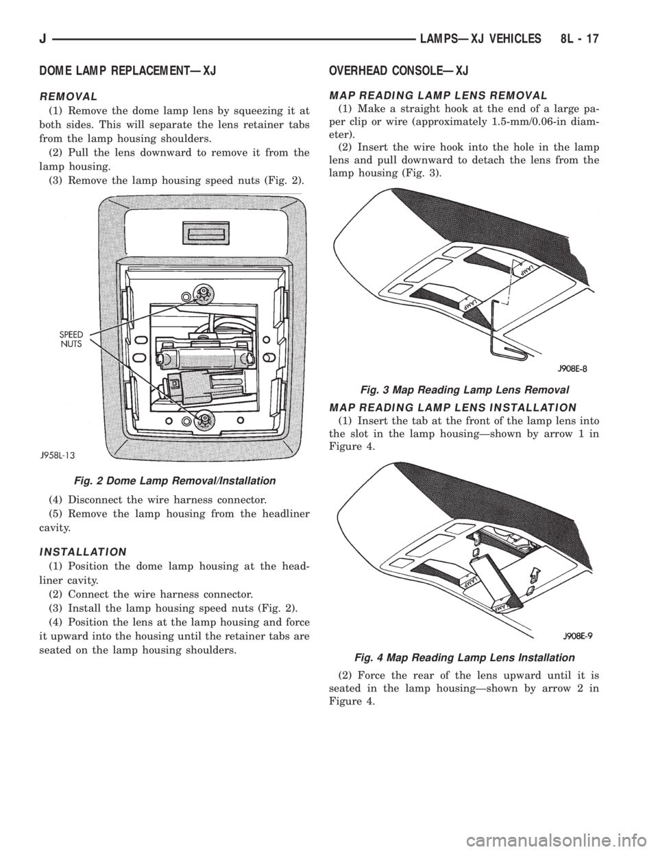
(3) Remove the lamp housing speed nuts (Fig. 2).
(4) Disconnect the wire harness connector.
(5) Remove the lamp housing from the headliner
cavity.
INSTALLATION
(1) Position the dome lamp housing at the head-
liner cavity.
(2) Connect the wire harness connector.
(3) Install the lamp housing speed nuts (Fig. 2).
(4) Position the lens at the lamp housing and force
it upward into the housing until the retainer tabs are
seated on the lamp housing shoulders.
OVERHEAD CONSOLEÐXJ
MAP READING LAMP LENS REMOVAL
(1) Make a straight hook at the end of a large pa-
per clip or wire (approximately 1.5-mm/0.06-in diam-
eter).
(2) Insert the wire hook into the hole in the lamp
lens and pull downward to detach the lens from the
lamp housing (Fig. 3).
MAP READING LAMP LENS INSTALLATION
(1) Insert the tab at the front of the lamp lens into
the slot in the lamp housingÐshown by arrow 1 in
Figure 4.
(2) Force the rear of the lens upward until it is
seated in the lamp housingÐshown by arrow 2 in
Figure 4.
Fig. 2 Dome Lamp Removal/Installation
Fig. 3 Map Reading Lamp Lens Removal
Fig. 4 Map Reading Lamp Lens Installation
JLAMPSÐXJ VEHICLES 8L - 17
Page 486 of 2158
HEADLAMP SWITCHÐYJ
To remove or replace the headlamp switch, refer to
Group 8E, Instrument Panel and Gauges.
FOG LAMP SWITCH REPLACEMENTÐYJ
REMOVAL
The fog lamp switch is located on the instrument
panel at the right of the steering column. The fog
lamp circuit relay is located below the left headlamp.
(1) Disconnect the battery negative cable.
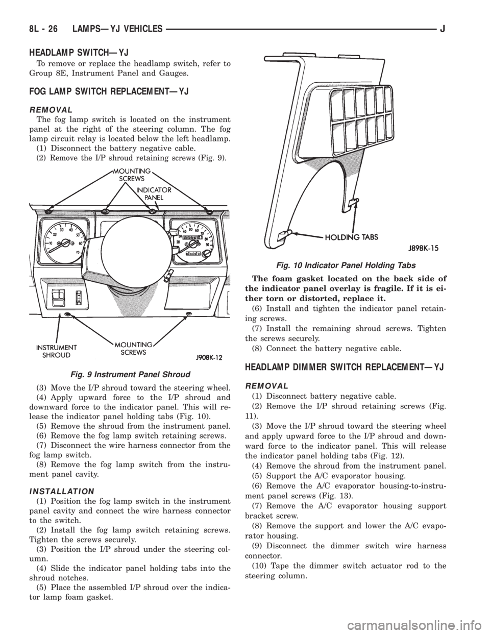
(2) Remove the I/P shroud retaining screws (Fig. 9).
(3) Move the I/P shroud toward the steering wheel.
(4) Apply upward force to the I/P shroud and
downward force to the indicator panel. This will re-
lease the indicator panel holding tabs (Fig. 10).
(5) Remove the shroud from the instrument panel.
(6) Remove the fog lamp switch retaining screws.
(7) Disconnect the wire harness connector from the
fog lamp switch.
(8) Remove the fog lamp switch from the instru-
ment panel cavity.
INSTALLATION
(1) Position the fog lamp switch in the instrument
panel cavity and connect the wire harness connector
to the switch.
(2) Install the fog lamp switch retaining screws.
Tighten the screws securely.
(3) Position the I/P shroud under the steering col-
umn.
(4) Slide the indicator panel holding tabs into the
shroud notches.
(5) Place the assembled I/P shroud over the indica-
tor lamp foam gasket.The foam gasket located on the back side of
the indicator panel overlay is fragile. If it is ei-
ther torn or distorted, replace it.
(6) Install and tighten the indicator panel retain-
ing screws.
(7) Install the remaining shroud screws. Tighten
the screws securely.
(8) Connect the battery negative cable.
HEADLAMP DIMMER SWITCH REPLACEMENTÐYJ
REMOVAL
(1) Disconnect battery negative cable.
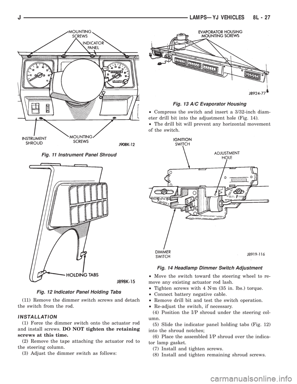
(2) Remove the I/P shroud retaining screws (Fig.
11).
(3) Move the I/P shroud toward the steering wheel
and apply upward force to the I/P shroud and down-
ward force to the indicator panel. This will release
the indicator panel holding tabs (Fig. 12).
(4) Remove the shroud from the instrument panel.
(5) Support the A/C evaporator housing.
(6) Remove the A/C evaporator housing-to-instru-
ment panel screws (Fig. 13).
(7) Remove the A/C evaporator housing support
bracket screw.
(8) Remove the support and lower the A/C evapo-
rator housing.
(9) Disconnect the dimmer switch wire harness
connector.
(10) Tape the dimmer switch actuator rod to the
steering column.
Fig. 9 Instrument Panel Shroud
Fig. 10 Indicator Panel Holding Tabs
8L - 26 LAMPSÐYJ VEHICLESJ
Page 487 of 2158
(11) Remove the dimmer switch screws and detach
the switch from the rod.
INSTALLATION
(1) Force the dimmer switch onto the actuator rod
and install screws.DO NOT tighten the retaining
screws at this time.
(2) Remove the tape attaching the actuator rod to
the steering column.
(3) Adjust the dimmer switch as follows:²Compress the switch and insert a 3/32-inch diam-
eter drill bit into the adjustment hole (Fig. 14).
²The drill bit will prevent any horizontal movement
of the switch.
²Move the switch toward the steering wheel to re-
move any existing actuator rod lash.
²Tighten screws with 4 Nzm (35 in. lbs.) torque.
²Connect battery negative cable.
²Remove drill bit and test the switch operation.
²Re-adjust the switch, if necessary.
(4) Position the I/P shroud under the steering col-
umn.
(5) Slide the indicator panel holding tabs (Fig. 12)
into the shroud notches;
(6) Place the assembled I/P shroud over the indica-
tor lamp gasket.
(7) Install and tighten screws.
(8) Install and tighten remaining shroud screws.
Fig. 11 Instrument Panel Shroud
Fig. 12 Indicator Panel Holding Tabs
Fig. 13 A/C Evaporator Housing
Fig. 14 Headlamp Dimmer Switch Adjustment
JLAMPSÐYJ VEHICLES 8L - 27
Page 491 of 2158
INTERIOR LAMPS
INDEX
page page
Dome/Courtesy Lamp Service InformationÐYJ . . . 31
Dome/Courtesy Lamp Trouble DiagnosisÐYJ.... 31Hardtop Dome/Cargo Lamp Bulb ReplacementÐYJ
Vehicles............................... 31
DOME/COURTESY LAMP SERVICE
INFORMATIONÐYJ
The dome/cargo and underpanel courtesy lamps are
controlled via ON/OFF switches. The ON/OFF
switches are in the lamp ground circuits. Voltage via
the dome/courtesy lamp fuse is applied directly to the
lamp bulbs. When either door is opened, the door pil-
lar switch contacts close and provide a direct path to
vehicle body ground.
The dome/cargo and underpanel courtesy lamps
can also be turned on via the interior lamp illumina-
tion rheostat.
DOME/COURTESY LAMP TROUBLE DIAGNOSISÐ
YJ
ALL LAMPS INOPERATIVE FROM INTERIOR
LAMP ILLUMINATION RHEOSTAT
(1) Rotate the interior lamp illumination rheostat
in an upward direction. The lamps should light. If
not OK, remove, inspect and test the dome lamp
fuse. Replace if bad.
(2) If the fuse is OK, repair the open circuit in the
wire harness to vehicle body ground.
(3) If lamp still does not light, replace the switch.
ONE LAMP INOPERATIVE
(1) Measure the resistance across the bulb holder
terminals. The ohmmeter should indicate zero ohms.
If not, replace the bulb.
(2) Measure the voltage between the voltage side
of the bulb holder and vehicle body ground. The volt-
meter should indicate battery voltage. If not, repair
the open circuit in the wire harness to the splice.
LAMPS INOPERATIVE WITH ONE OR MORE
DOORS OPENED
(1) Remove the inoperative switch from the door
pillar and connect the switch wire directly to ground.
The lamp should light.(2) If not, check for an open circuit in black
(ground) wire. Repair as necessary. If lamps still do
not light, replace the switch.
HARDTOP DOME/CARGO LAMP BULB
REPLACEMENTÐYJ VEHICLES
REMOVAL
(1) Remove the dome/cargo lamp lens by squeezing
it at both sides. This will separate the lens retainer
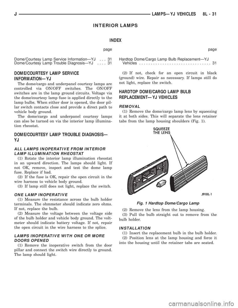
tabs from the lamp housing shoulders (Fig. 1).
(2) Remove the lens from the lamp housing.
(3) Pull the bulb straight out to remove from the
bulb holder.
INSTALLATION
(1) Insert the replacement bulb in the bulb holder.
(2) Position lens at the lamp housing and force it
into the housing until the retainer tabs are seated.
Fig. 1 Hardtop Dome/Cargo Lamp
JLAMPSÐYJ VEHICLES 8L - 31
Page 500 of 2158
(9) Allow epoxy to cure 24 hours at room tempera-
ture or use heat gun with a 260É-371ÉC (500É-700ÉF)
range for 15 minutes. Hold gun approximately
254mm (10 inches) from repaired area.
(10) After conductive epoxy is properly cured re-
move wedge or clamp from terminal or pigtail and
check operation of rear window defogger. Do not at-
tach connectors until curing is complete.
DEFOGGER SWITCH REMOVE/INSTALL
XJ MODELS
(1) Remove the instrument cluster bezel. Refer to
Group 8E - Instrument Panel and Gauges for proce-
dure.
(2) Remove the switch housing panel.
(3) Unplug the switch connector. Slightly depress
the switch mounting tabs and remove the switch.
(4) Reverse removal procedures to install.
YJ MODELS
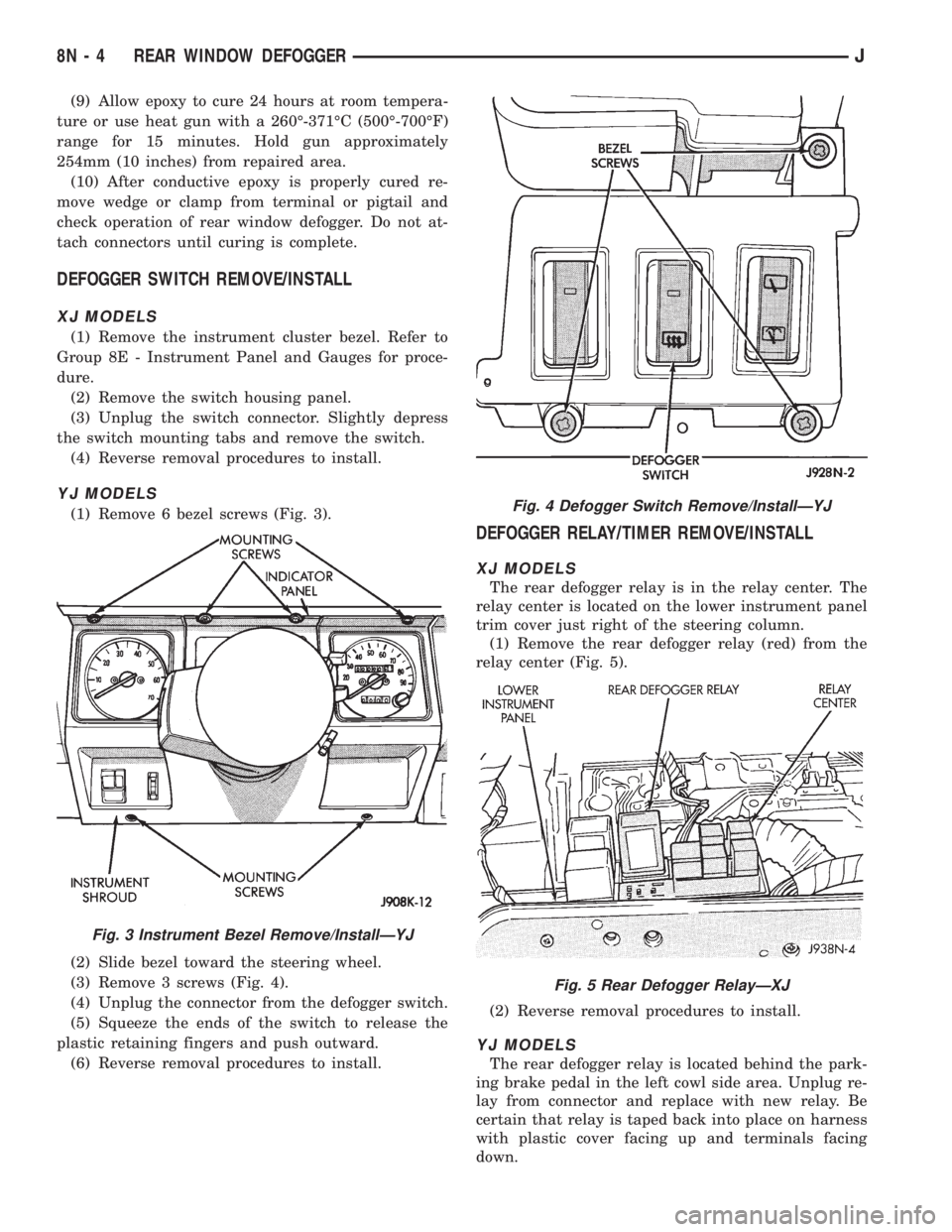
(1) Remove 6 bezel screws (Fig. 3).
(2) Slide bezel toward the steering wheel.
(3) Remove 3 screws (Fig. 4).
(4) Unplug the connector from the defogger switch.
(5) Squeeze the ends of the switch to release the
plastic retaining fingers and push outward.
(6) Reverse removal procedures to install.
DEFOGGER RELAY/TIMER REMOVE/INSTALL
XJ MODELS
The rear defogger relay is in the relay center. The
relay center is located on the lower instrument panel
trim cover just right of the steering column.
(1) Remove the rear defogger relay (red) from the
relay center (Fig. 5).
(2) Reverse removal procedures to install.
YJ MODELS
The rear defogger relay is located behind the park-
ing brake pedal in the left cowl side area. Unplug re-
lay from connector and replace with new relay. Be
certain that relay is taped back into place on harness
with plastic cover facing up and terminals facing
down.
Fig. 3 Instrument Bezel Remove/InstallÐYJ
Fig. 4 Defogger Switch Remove/InstallÐYJ
Fig. 5 Rear Defogger RelayÐXJ
8N - 4 REAR WINDOW DEFOGGERJ
Page 515 of 2158
SERVICE PROCEDURES
POWER SEAT SWITCH REMOVE/INSTALL
(1) Disconnect battery negative cable.
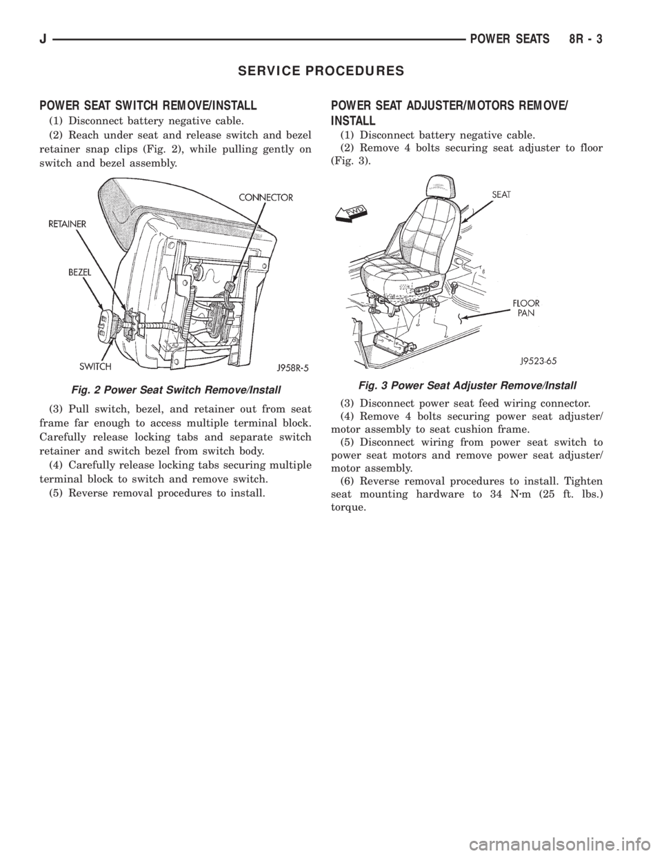
(2) Reach under seat and release switch and bezel
retainer snap clips (Fig. 2), while pulling gently on
switch and bezel assembly.
(3) Pull switch, bezel, and retainer out from seat
frame far enough to access multiple terminal block.
Carefully release locking tabs and separate switch
retainer and switch bezel from switch body.
(4) Carefully release locking tabs securing multiple
terminal block to switch and remove switch.
(5) Reverse removal procedures to install.
POWER SEAT ADJUSTER/MOTORS REMOVE/
INSTALL
(1) Disconnect battery negative cable.
(2) Remove 4 bolts securing seat adjuster to floor
(Fig. 3).
(3) Disconnect power seat feed wiring connector.
(4) Remove 4 bolts securing power seat adjuster/
motor assembly to seat cushion frame.
(5) Disconnect wiring from power seat switch to
power seat motors and remove power seat adjuster/
motor assembly.
(6) Reverse removal procedures to install. Tighten
seat mounting hardware to 34 Nzm (25 ft. lbs.)
torque.
Fig. 2 Power Seat Switch Remove/InstallFig. 3 Power Seat Adjuster Remove/Install
JPOWER SEATS 8R - 3
Page 545 of 2158

FUSE/FUSE BLOCK
GENERAL INFORMATION
This section covers the Fuse Block and all circuits
involved with it. For additional information on sys-
tem operation, refer to the appropriate section of the
wiring diagrams.
DIAGRAM INDEX
Component Page
ABS Control Module......................8W-10-4
ABS Warning Lamp Relay...................8W-10-2
Chime/Buzzer Module.................8W-10-2, 9, 10
Circuit Breaker Cavity 16...................8W-10-12
In-Line Circuit Breaker (Wipers)...............8W-10-5
In-Line Circuit Breaker (Stop Lamp Relay)........8W-10-12
Daytime Running Lamps Module..............8W-10-8
Fuse 1 (Fuse Block).......................8W-10-4
Fuse 2 (Fuse Block).......................8W-10-5
Fuse 3 (Fuse Block).....................8W-10-4, 8
Fuse 3 (PDC)........................8W-10-6, 12
Fuse 4 (Fuse Block).......................8W-10-7
Fuse 5 (Fuse Block).......................8W-10-5
Fuse 5 (PDC)........................8W-10-7, 10
Fuse 6 (Fuse Block).......................8W-10-4
Fuse 6 (PDC).........................8W-10-4, 8
Fuse 7 (Fuse Block)....................8W-10-4, 10
Fuse 8 (Fuse Block).......................8W-10-5
Fuse 9 (Fuse Block).......................8W-10-6
Fuse 10 (Fuse Block)......................8W-10-4
Fuse 11 (Fuse Block)......................8W-10-9
Fuse 11 (PDC)..........................8W-10-8
Fuse 12 (PDC)..........................8W-10-8
Fuse 13 (Fuse Block)......................8W-10-9
Fuse 14 (Fuse Block)......................8W-10-9
Fuse 15 (Fuse Block)......................8W-10-7
Fuse 15 (PDC)..........................8W-10-6
Fuse 17 (Fuse Block)......................8W-10-9
Fuse Block.............................8W-10-2
Headlamp Delay Module....................8W-10-9
Headlamp Switch......................8W-10-7, 10
Heated Rear Window Relay.................8W-10-10
Ignition Switch........................8W-10-4, 8
Instrument Cluster.......................8W-10-11
Overhead Console.....................8W-10-9, 11
Powertrain Control Module..................8W-10-8
Remote Keyless Entry Module................8W-10-9
J8W-10 FUSE/FUSE BLOCKÐXJ VEHICLES 8W - 10 - 1
Page 557 of 2158

POWER DISTRIBUTION
GENERAL INFORMATION
This section covers the Power Distribution Center
(PDC) and all circuits involved with it. For additional
information on system operation, refer to the appro-
priate section of the wiring diagrams.
DIAGRAM INDEX
Component Page
A/C Compressor Clutch Relay..............8W-11-3, 11
ABS Control Module.....................8W-11-6, 7
ABS Power Relay......................8W-11-3, 6
ABS Pump Motor Relay..................8W-11-3, 7
Automatic Shut Down Relay................8W-11-3, 9
Chime/Buzzer Module..................8W-11-10, 14
Circuit Breaker Cavity 16 (Fuse Block)..........8W-11-13
Combination Flasher......................8W-11-17
Daytime Running Lamp Module.............8W-11-5, 10
Diode D101............................8W-11-6
Engine Starter Motor Relay................8W-11-3, 4
Fuel Pump Relay.......................8W-11-3, 8
Fuse 1 (PDC)..........................8W-11-13
Fuse 3 (PDC)..........................8W-11-12
Fuse 4 (Fuse Block)......................8W-11-14
Fuse 4 (PDC)..........................8W-11-15
Fuse 5 (PDC)..........................8W-11-14
Fuse 6 (PDC)....................8W-11-4, 7, 10, 15
Fuse 7 (Fuse Block).......................8W-11-7
Fuse 7 (PDC)...........................8W-11-4
Fuse 8 (PDC)...........................8W-11-7
Fuse 9 (Fuse Block)......................8W-11-12
Fuse 9 (PDC)..........................8W-11-13
Fuse 10 (PDC)........................8W-11-6, 8
Fuse 11 (Fuse Block).....................8W-11-13
Fuse 11 (PDC).........................8W-11-10
Fuse 12 (PDC).........................8W-11-15Component Page
Fuse 13 (PDC)..........................8W-11-4
Fuse 14 (PDC)..........................8W-11-8
Fuse 15 (Fuse Block).....................8W-11-14
Fuse 15 (PDC)..........................8W-11-8
Fuse 16 (PDC).........................8W-11-12
Fuse 17 (Fuse Block).....................8W-11-10
Headlamp Delay Module.................8W-11-10, 14
Headlamp Switch........................8W-11-14
Headlamp Dimmer Switch..................8W-11-14
Horn Rear Window Relay..................8W-11-17
Horn Relay............................8W-11-17
Ignition Switch...................8W-11-4, 7, 10, 15
In-Line Circuit Breaker (Stop Lamp Relay)........8W-11-13
LCD Illumination Relay....................8W-11-17
Overhead Console.....................8W-11-10, 14
Powertrain Control Module..........8W-11-4, 5, 8, 9, 11
Power Distribution Center...................8W-11-2
Power Door Lock Relay...................8W-11-16
Power Door Unlock Relay..................8W-11-16
Radiator Fan Control Relay................8W-11-3, 11
Remote Keyless Entry Module.............8W-11-10, 12
Relay Center...........................8W-11-16
Telltale Connector (I.P. Cluster)..........8W-11-6, 10, 12
Torque Converter Clutch (TCC) Relay...........8W-11-15
Transmission Control Module...............8W-11-5, 8
J8W-11 POWER DISTRIBUTIONÐXJ VEHICLES 8W - 11 - 1