1995 JEEP YJ ABS
[x] Cancel search: ABSPage 408 of 2158
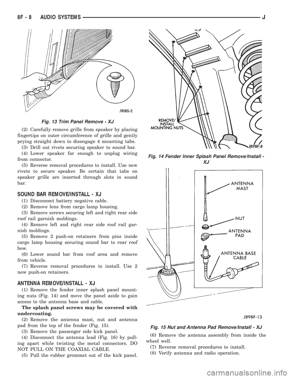
(2) Carefully remove grille from speaker by placing
fingertips on outer circumference of grille and gently
prying straight down to disengage 4 mounting tabs.
(3) Drill out rivets securing speaker to sound bar.
(4) Lower speaker far enough to unplug wiring
from connector.
(5) Reverse removal procedures to install. Use new
rivets to secure speaker. Be certain that tabs on
speaker grille are inserted through slots in sound
bar.
SOUND BAR REMOVE/INSTALL - XJ
(1) Disconnect battery negative cable.
(2) Remove lens from cargo lamp housing.
(3) Remove screws securing left and right rear side
roof rail garnish moldings.
(4) Remove left and right rear side roof rail gar-
nish moldings.
(5) Remove 2 push-on retainers from pins inside
cargo lamp housing securing sound bar to rear roof
bow.
(6) Lower sound bar from roof area and remove
from vehicle.
(7) Reverse removal procedures to install. Use 2
new push-on retainers.
ANTENNA REMOVE/INSTALL - XJ
(1) Remove the fender inner splash panel mount-
ing nuts (Fig. 14) and move the panel aside to gain
access to the antenna base and cable.
The splash panel screws may be covered with
undercoating.
(2) Remove the antenna mast, nut and antenna
pad from the top of the fender (Fig. 15).
(3) Remove the passenger side kick panel.
(4) Disconnect the antenna lead (Fig. 16) by pull-
ing apart while twisting the metal connectors. DO
NOT PULL ON THE COAXIAL CABLE.
(5) Pull the rubber grommet out of the kick panel.(6) Remove the antenna assembly from inside the
wheel well.
(7) Reverse removal procedures to install.
(8) Verify antenna and radio operation.
Fig. 13 Trim Panel Remove - XJ
Fig. 14 Fender Inner Splash Panel Remove/Install -
XJ
Fig. 15 Nut and Antenna Pad Remove/Install - XJ
8F - 8 AUDIO SYSTEMSJ
Page 426 of 2158
SERVO CABLE REMOVE/INSTALL
(1) Remove air cleaner.
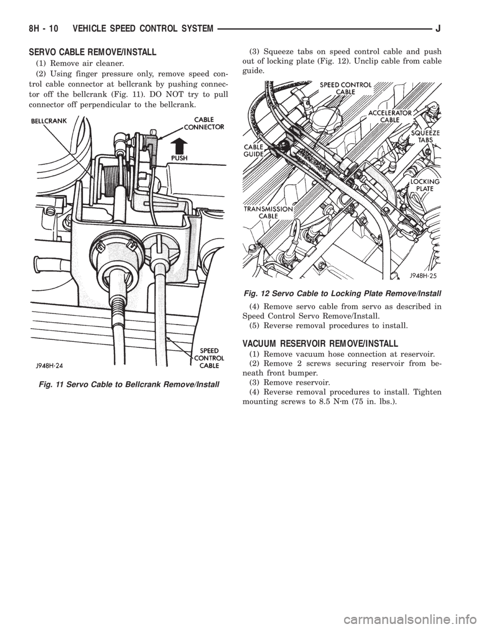
(2) Using finger pressure only, remove speed con-
trol cable connector at bellcrank by pushing connec-
tor off the bellcrank (Fig. 11). DO NOT try to pull
connector off perpendicular to the bellcrank.(3) Squeeze tabs on speed control cable and push
out of locking plate (Fig. 12). Unclip cable from cable
guide.
(4) Remove servo cable from servo as described in
Speed Control Servo Remove/Install.
(5) Reverse removal procedures to install.
VACUUM RESERVOIR REMOVE/INSTALL
(1) Remove vacuum hose connection at reservoir.
(2) Remove 2 screws securing reservoir from be-
neath front bumper.
(3) Remove reservoir.
(4) Reverse removal procedures to install. Tighten
mounting screws to 8.5 Nzm (75 in. lbs.).
Fig. 11 Servo Cable to Bellcrank Remove/Install
Fig. 12 Servo Cable to Locking Plate Remove/Install
8H - 10 VEHICLE SPEED CONTROL SYSTEMJ
Page 434 of 2158
(24) Pry up locking tabs of steering column connec-
tor and remove connector from column bracket.
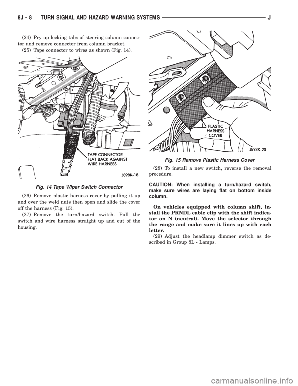
(25) Tape connector to wires as shown (Fig. 14).
(26) Remove plastic harness cover by pulling it up
and over the weld nuts then open and slide the cover
off the harness (Fig. 15).
(27) Remove the turn/hazard switch. Pull the
switch and wire harness straight up and out of the
housing.(28) To install a new switch, reverse the removal
procedure.
CAUTION: When installing a turn/hazard switch,
make sure wires are laying flat on bottom inside
column.
On vehicles equipped with column shift, in-
stall the PRNDL cable clip with the shift indica-
tor on N (neutral). Move the selector through
the range and make sure it lines up with each
letter.
(29) Adjust the headlamp dimmer switch as de-
scribed in Group 8L - Lamps.
Fig. 15 Remove Plastic Harness Cover
Fig. 14 Tape Wiper Switch Connector
8J - 8 TURN SIGNAL AND HAZARD WARNING SYSTEMSJ
Page 442 of 2158
(12) Reverse removal procedures to install. Tighten
fasteners as follows:
²wiring connector to switch retaining screw to 2
Nzm (17 in. lbs.)
²multi-function switch to column retaining screws
to2Nzm (17 in. lbs.)
²steering column shroud retaining screws to 2 Nzm
(17 in. lbs.).
LIFTGATE WIPER/WASHER SWITCH REMOVE/
INSTALL
(1) Remove the instrument cluster bezel. Refer to
Group 8E - Instrument Panel and Gauges for proce-
dure.
(2) Remove the switch housing panel.
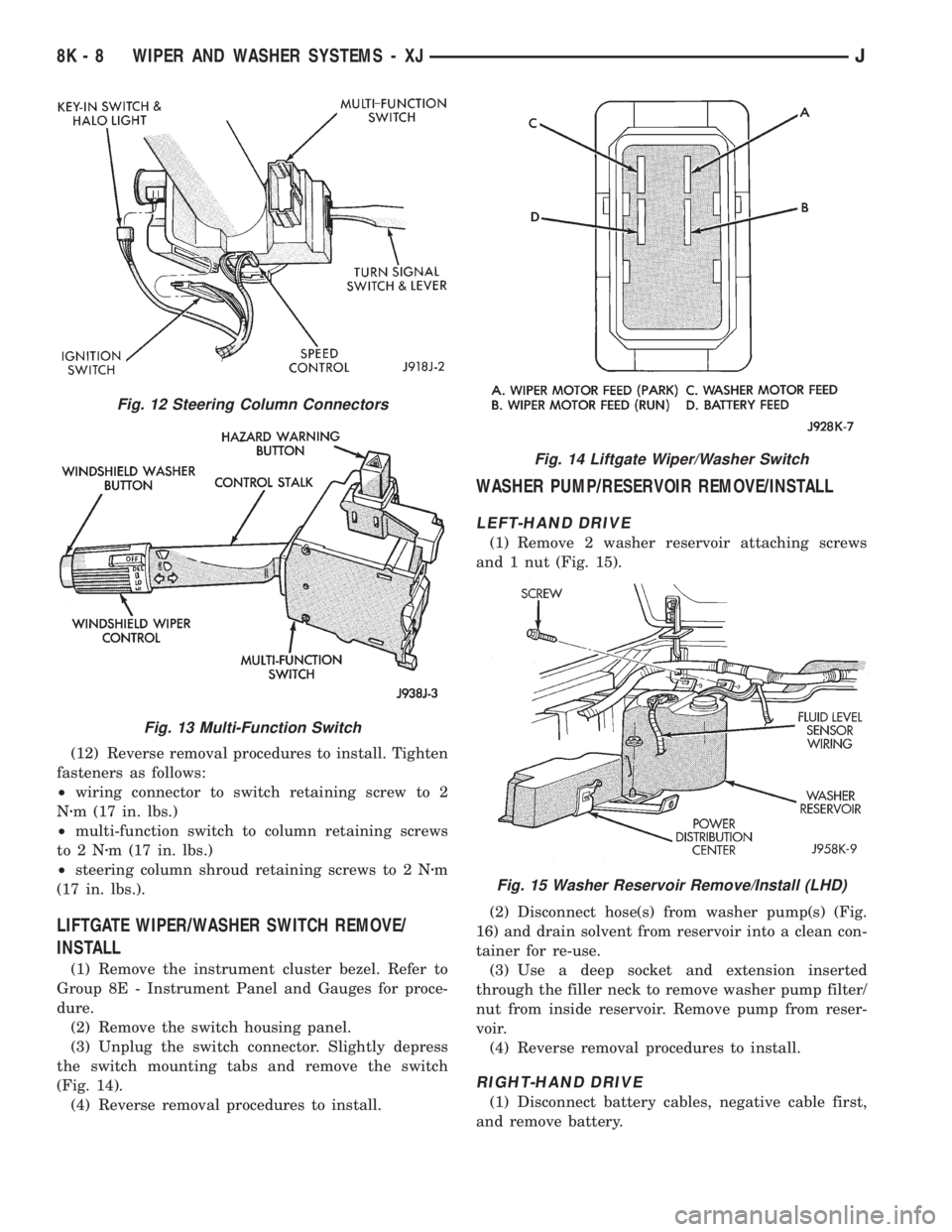
(3) Unplug the switch connector. Slightly depress
the switch mounting tabs and remove the switch
(Fig. 14).
(4) Reverse removal procedures to install.
WASHER PUMP/RESERVOIR REMOVE/INSTALL
LEFT-HAND DRIVE
(1) Remove 2 washer reservoir attaching screws
and 1 nut (Fig. 15).
(2) Disconnect hose(s) from washer pump(s) (Fig.
16) and drain solvent from reservoir into a clean con-
tainer for re-use.
(3) Use a deep socket and extension inserted
through the filler neck to remove washer pump filter/
nut from inside reservoir. Remove pump from reser-
voir.
(4) Reverse removal procedures to install.
RIGHT-HAND DRIVE
(1) Disconnect battery cables, negative cable first,
and remove battery.
Fig. 12 Steering Column Connectors
Fig. 13 Multi-Function Switch
Fig. 14 Liftgate Wiper/Washer Switch
Fig. 15 Washer Reservoir Remove/Install (LHD)
8K - 8 WIPER AND WASHER SYSTEMS - XJJ
Page 456 of 2158
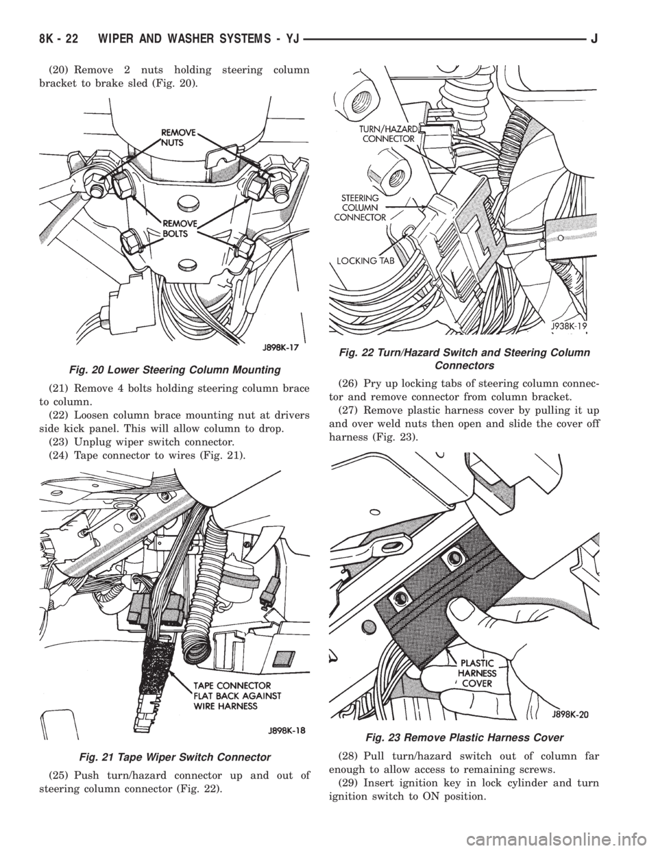
(20) Remove 2 nuts holding steering column
bracket to brake sled (Fig. 20).
(21) Remove 4 bolts holding steering column brace
to column.
(22) Loosen column brace mounting nut at drivers
side kick panel. This will allow column to drop.
(23) Unplug wiper switch connector.
(24) Tape connector to wires (Fig. 21).
(25) Push turn/hazard connector up and out of
steering column connector (Fig. 22).(26) Pry up locking tabs of steering column connec-
tor and remove connector from column bracket.
(27) Remove plastic harness cover by pulling it up
and over weld nuts then open and slide the cover off
harness (Fig. 23).
(28) Pull turn/hazard switch out of column far
enough to allow access to remaining screws.
(29) Insert ignition key in lock cylinder and turn
ignition switch to ON position.
Fig. 20 Lower Steering Column Mounting
Fig. 21 Tape Wiper Switch Connector
Fig. 22 Turn/Hazard Switch and Steering Column
Connectors
Fig. 23 Remove Plastic Harness Cover
8K - 22 WIPER AND WASHER SYSTEMS - YJJ
Page 458 of 2158
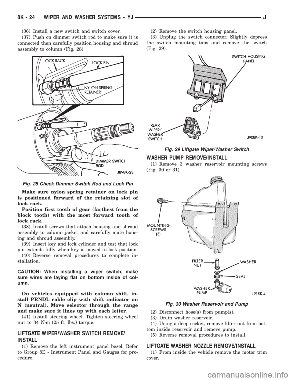
(36) Install a new switch and switch cover.
(37) Push on dimmer switch rod to make sure it is
connected then carefully position housing and shroud
assembly to column (Fig. 28).
Make sure nylon spring retainer on lock pin
is positioned forward of the retaining slot of
lock rack.
Position first tooth of gear (farthest from the
block tooth) with the most forward tooth of
lock rack.
(38) Install screws that attach housing and shroud
assembly to column jacket and carefully mate hous-
ing and shroud assembly.
(39) Insert key and lock cylinder and test that lock
pin extends fully when key is moved to lock position.
(40) Reverse removal procedures to complete in-
stallation.
CAUTION: When installing a wiper switch, make
sure wires are laying flat on bottom inside of col-
umn.
On vehicles equipped with column shift, in-
stall PRNDL cable clip with shift indicator on
N (neutral). Move selector through the range
and make sure it lines up with each letter.
(41) Install steering wheel. Tighten steering wheel
nut to 34 Nzm (25 ft. lbs.) torque.
LIFTGATE WIPER/WASHER SWITCH REMOVE/
INSTALL
(1) Remove the left instrument panel bezel. Refer
to Group 8E - Instrument Panel and Gauges for pro-
cedure.(2) Remove the switch housing panel.
(3) Unplug the switch connector. Slightly depress
the switch mounting tabs and remove the switch
(Fig. 29).
WASHER PUMP REMOVE/INSTALL
(1) Remove 3 washer reservoir mounting screws
(Fig. 30 or 31).
(2) Disconnect hose(s) from pump(s).
(3) Drain washer reservoir.
(4) Using a deep socket, remove filter nut from bot-
tom inside reservoir and remove pump.
(5) Reverse removal procedures to install.
LIFTGATE WASHER NOZZLE REMOVE/INSTALL
(1) From inside the vehicle remove the motor trim
cover.
Fig. 28 Check Dimmer Switch Rod and Lock Pin
Fig. 29 Liftgate Wiper/Washer Switch
Fig. 30 Washer Reservoir and Pump
8K - 24 WIPER AND WASHER SYSTEMS - YJJ
Page 470 of 2158
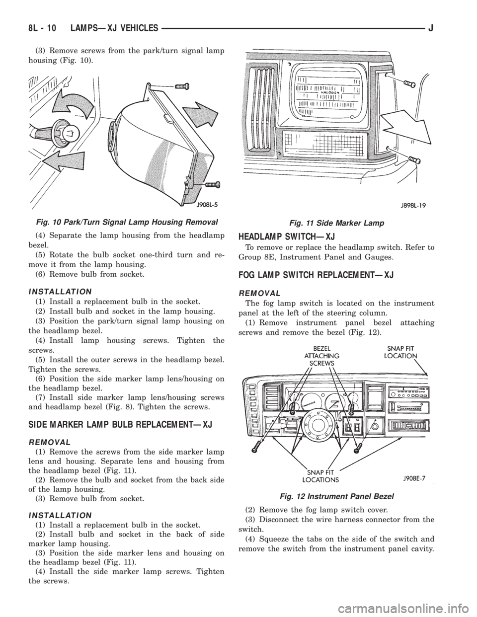
(3) Remove screws from the park/turn signal lamp
housing (Fig. 10).
(4) Separate the lamp housing from the headlamp
bezel.
(5) Rotate the bulb socket one-third turn and re-
move it from the lamp housing.
(6) Remove bulb from socket.
INSTALLATION
(1) Install a replacement bulb in the socket.
(2) Install bulb and socket in the lamp housing.
(3) Position the park/turn signal lamp housing on
the headlamp bezel.
(4) Install lamp housing screws. Tighten the
screws.
(5) Install the outer screws in the headlamp bezel.
Tighten the screws.
(6) Position the side marker lamp lens/housing on
the headlamp bezel.
(7) Install side marker lamp lens/housing screws
and headlamp bezel (Fig. 8). Tighten the screws.
SIDE MARKER LAMP BULB REPLACEMENTÐXJ
REMOVAL
(1) Remove the screws from the side marker lamp
lens and housing. Separate lens and housing from
the headlamp bezel (Fig. 11).
(2) Remove the bulb and socket from the back side
of the lamp housing.
(3) Remove bulb from socket.
INSTALLATION
(1) Install a replacement bulb in the socket.
(2) Install bulb and socket in the back of side
marker lamp housing.
(3) Position the side marker lens and housing on
the headlamp bezel (Fig. 11).
(4) Install the side marker lamp screws. Tighten
the screws.
HEADLAMP SWITCHÐXJ
To remove or replace the headlamp switch. Refer to
Group 8E, Instrument Panel and Gauges.
FOG LAMP SWITCH REPLACEMENTÐXJ
REMOVAL
The fog lamp switch is located on the instrument
panel at the left of the steering column.
(1) Remove instrument panel bezel attaching
screws and remove the bezel (Fig. 12).
(2) Remove the fog lamp switch cover.
(3) Disconnect the wire harness connector from the
switch.
(4) Squeeze the tabs on the side of the switch and
remove the switch from the instrument panel cavity.
Fig. 10 Park/Turn Signal Lamp Housing RemovalFig. 11 Side Marker Lamp
Fig. 12 Instrument Panel Bezel
8L - 10 LAMPSÐXJ VEHICLESJ
Page 471 of 2158
INSTALLATION
(1) Squeeze the tabs on the side of the fog lamp
switch and insert the switch in the instrument panel
cavity.
(2) Connect the wire harness connector to the
switch.
(3) Install the fog lamp switch cover.
(4) Position the bezel on the instrument panel and
install the attaching screws. Tighten the screws se-
curely.
MULTI-FUNCTION SWITCH SERVICE
PROCEDURESÐXJ
REMOVAL
(1) Disconnect battery negative cable.
(2) Remove lower instrument panel screws along
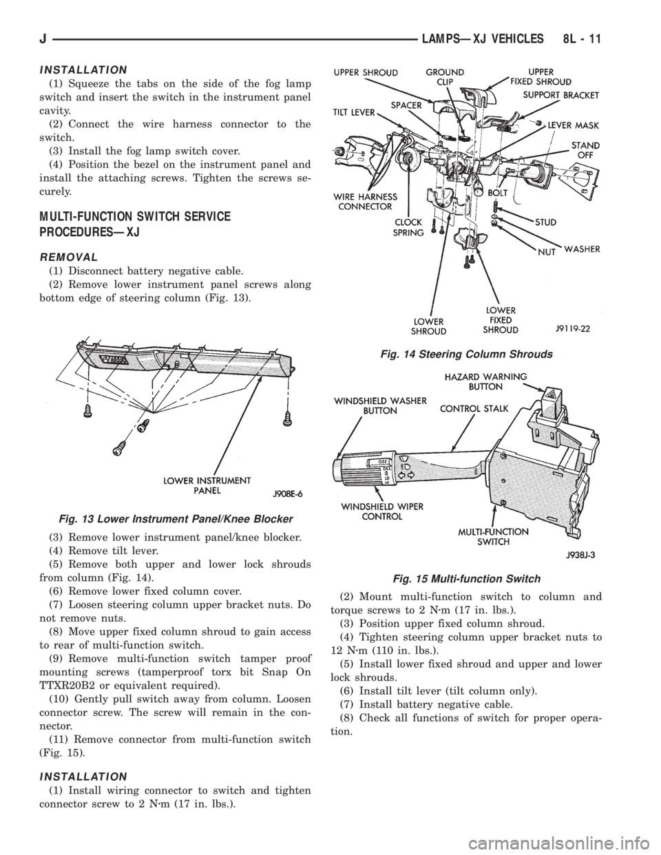
bottom edge of steering column (Fig. 13).
(3) Remove lower instrument panel/knee blocker.
(4) Remove tilt lever.
(5) Remove both upper and lower lock shrouds
from column (Fig. 14).
(6) Remove lower fixed column cover.
(7) Loosen steering column upper bracket nuts. Do
not remove nuts.
(8) Move upper fixed column shroud to gain access
to rear of multi-function switch.
(9) Remove multi-function switch tamper proof
mounting screws (tamperproof torx bit Snap On
TTXR20B2 or equivalent required).
(10) Gently pull switch away from column. Loosen
connector screw. The screw will remain in the con-
nector.
(11) Remove connector from multi-function switch
(Fig. 15).
INSTALLATION
(1) Install wiring connector to switch and tighten
connector screw to 2 Nzm (17 in. lbs.).(2) Mount multi-function switch to column and
torque screws to 2 Nzm (17 in. lbs.).
(3) Position upper fixed column shroud.
(4) Tighten steering column upper bracket nuts to
12 Nzm (110 in. lbs.).
(5) Install lower fixed shroud and upper and lower
lock shrouds.
(6) Install tilt lever (tilt column only).
(7) Install battery negative cable.
(8) Check all functions of switch for proper opera-
tion.
Fig. 13 Lower Instrument Panel/Knee Blocker
Fig. 14 Steering Column Shrouds
Fig. 15 Multi-function Switch
JLAMPSÐXJ VEHICLES 8L - 11