Page 1763 of 2198

DOORS
INDEX
page page
Door Alignment AdjustmentÐMajor............ 41
Door Alignment AdjustmentÐMinor............ 37
Door Edge Guard/Edge Protector StripÐXJ...... 54
Door External HandleÐXJ................... 48
Door Hinge/Hinge Pin ReplacementÐXJ........ 52
Door Inside Latch Release and Lock RodsÐXJ . . . 50
Door Key Lock CylinderÐXJ................. 47
Door Latch AdjustmentÐXJ.................. 48
Door LatchÐXJ.......................... 49
Door Removal/InstallationÐXJ............... 35
Door Restraint ReplacementÐXJ............. 41
Door Trim PanelÐXJ...................... 31
Door Window Exterior MoldingsÐXJ........... 54
Door Window Glass and Door Opening
Weatherstrip SealsÐXJ................... 55
Front Door Spacer BlocksÐTwo-Door Vehicles . . . 53
Front Door Window Glass RegulatorÐXJ........ 42Front Door Window GlassÐXJ............... 43
Liftgate AdjustmentÐXJ.................... 63
Liftgate HingeÐXJ........................ 60
Liftgate Latch/Key Lock Cylinder/StrikerÐXJ..... 61
Liftgate License Plate Lamp HousingÐXJ....... 65
Liftgate License Plate Screw Anchor and BumperÐXJ.65
Liftgate Opening Weatherstrip SealÐXJ........ 64
Liftgate Support Rod Ball Stud ReplacementÐXJ . 63
Liftgate Support Rod Cylinder DisposalÐXJ...... 63
Liftgate Support Rod CylinderÐXJ............. 62
Liftgate Trim PanelÐXJ..................... 59
LiftgateÐXJ............................. 58
Rear Door Stationary Window GlassÐXJ........ 46
Rear Door Window Glass RegulatorÐXJ........ 44
Rear Door Window GlassÐXJ................ 45
Service Information........................ 30
SERVICE INFORMATION
The door service procedures includes removal, in-
stallation and/or replacement of the following door
components:
²Door handles.²Armrests.
²Trim panels.
²Waterdams.
²Door restraints.
²Front doors.
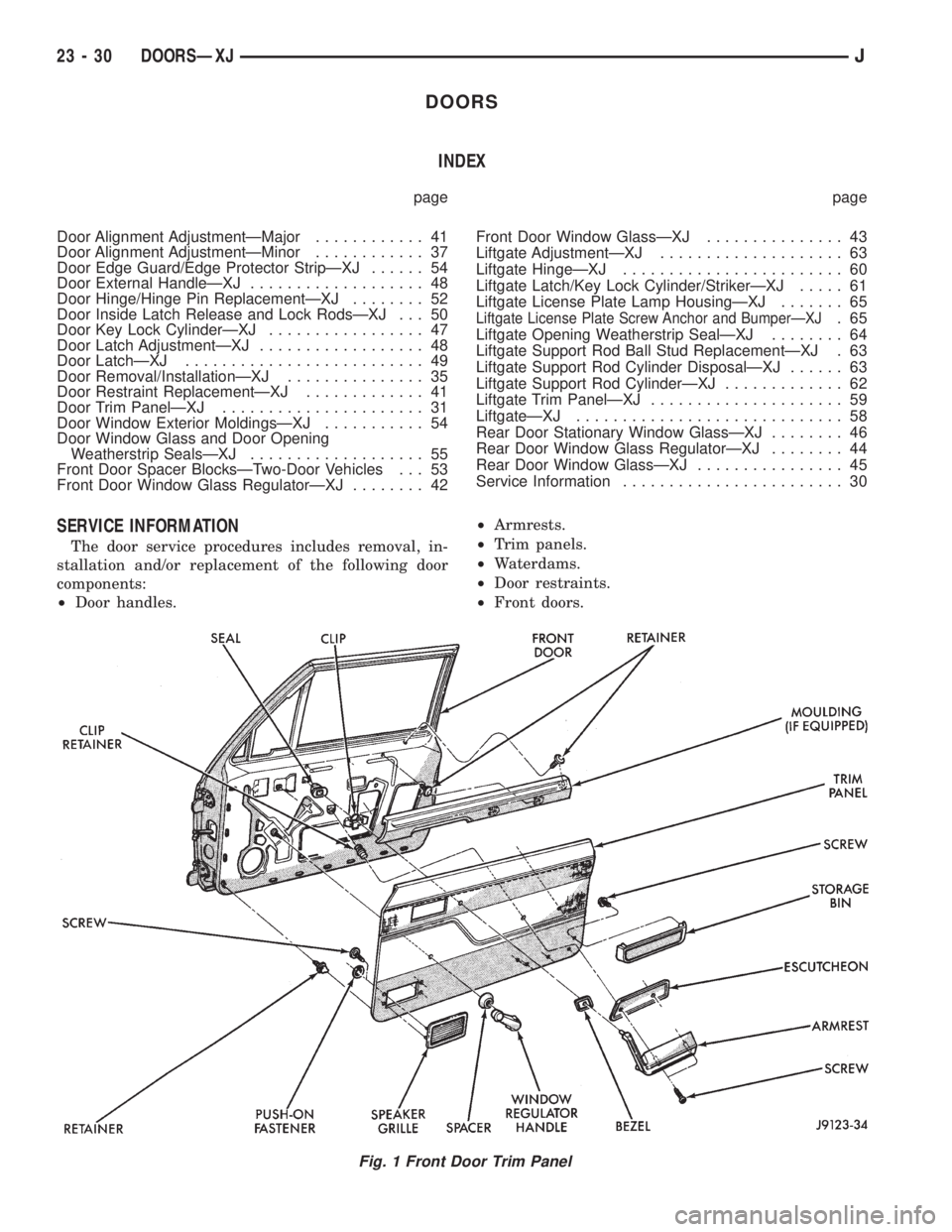
Fig. 1 Front Door Trim Panel
23 - 30 DOORSÐXJJ
Page 1764 of 2198
²Rear doors.
²Window glass regulators.
²Key lock cylinders.
²Door half-hinges.
²Liftgate.
²Liftgate hinges.
²Liftgate gas support rod cylinders.
²Rocker panel seals.
²Moldings/weatherstrip seals.DOOR TRIM PANELÐXJ
SERVICE INFORMATION
All attached components can be removed from door
trim panels (Fig. 1 and 2).
REMOVAL
(1) Remove the door inside latch release handle
screws (Fig. 3 and 4).
Fig. 2 Rear Door Trim Panel
Fig. 3 Front Door Inside Latch Release Handle
Fig. 4 Rear Door Inside Latch Release Handle
JDOORSÐXJ 23 - 31
Page 1765 of 2198
(2) Move the door handle outward and disconnect
the handle-to-latch rods (Fig. 5). For vehicles
equipped with power door locks/windows, disconnect
the wire harness connector (Fig. 6).
(3) Remove the regulator handle (Fig. 7) or, if
equipped, power window switches and bezel.
(4) Remove the armrest lower screws (Fig. 8 and
9).
(5) Pull armrest straight outward from panel and
remove.
Fig. 5 Door Inside Latch Release Rods
Fig. 6 Power Switch Wire Harness Connector
Fig. 7 Window Regulator Handles
Fig. 8 XJ Front Door Armrest Removal/Installation
23 - 32 DOORSÐXJJ
Page 1768 of 2198

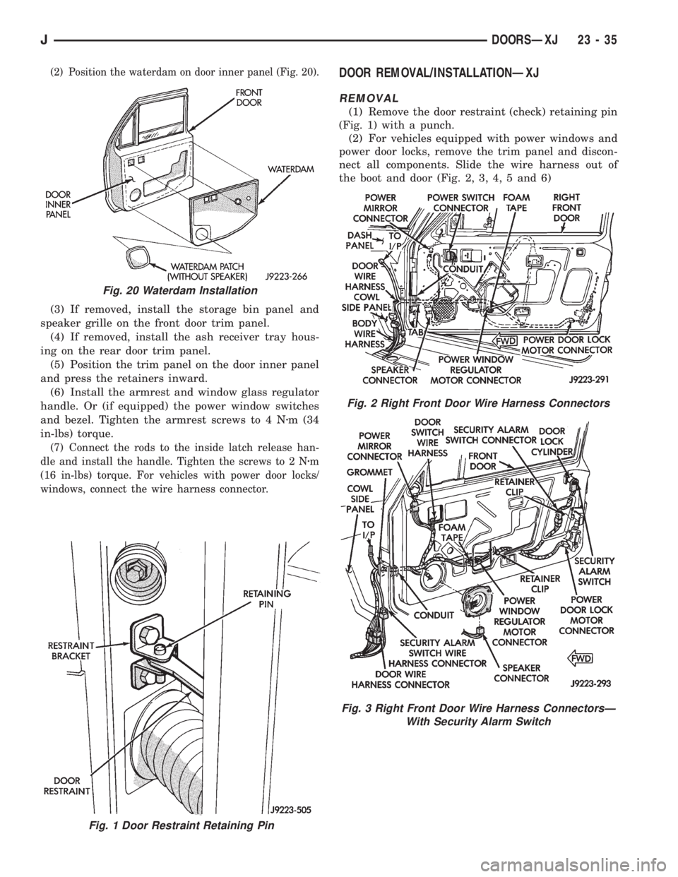
(2) Position the waterdam on door inner panel (Fig. 20).
(3) If removed, install the storage bin panel and
speaker grille on the front door trim panel.
(4) If removed, install the ash receiver tray hous-
ing on the rear door trim panel.
(5) Position the trim panel on the door inner panel
and press the retainers inward.
(6) Install the armrest and window glass regulator
handle. Or (if equipped) the power window switches
and bezel. Tighten the armrest screws to 4 Nzm (34
in-lbs) torque.
(7) Connect the rods to the inside latch release han-
dle and install the handle. Tighten the screws to 2 Nzm
(16 in-lbs) torque. For vehicles with power door locks/
windows, connect the wire harness connector.
DOOR REMOVAL/INSTALLATIONÐXJ
REMOVAL
(1) Remove the door restraint (check) retaining pin
(Fig. 1) with a punch.
(2) For vehicles equipped with power windows and
power door locks, remove the trim panel and discon-
nect all components. Slide the wire harness out of
the boot and door (Fig. 2, 3, 4, 5 and 6)
Fig. 1 Door Restraint Retaining Pin
Fig. 20 Waterdam Installation
Fig. 2 Right Front Door Wire Harness Connectors
Fig. 3 Right Front Door Wire Harness ConnectorsÐ
With Security Alarm Switch
JDOORSÐXJ 23 - 35
Page 1770 of 2198

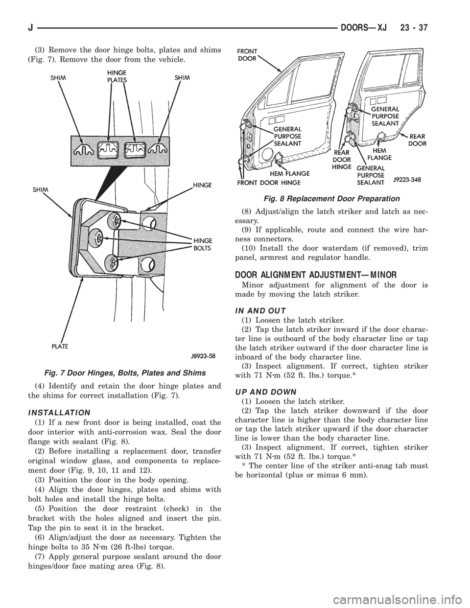
(3) Remove the door hinge bolts, plates and shims
(Fig. 7). Remove the door from the vehicle.
(4) Identify and retain the door hinge plates and
the shims for correct installation (Fig. 7).
INSTALLATION
(1) If a new front door is being installed, coat the
door interior with anti-corrosion wax. Seal the door
flange with sealant (Fig. 8).
(2) Before installing a replacement door, transfer
original window glass, and components to replace-
ment door (Fig. 9, 10, 11 and 12).
(3) Position the door in the body opening.
(4) Align the door hinges, plates and shims with
bolt holes and install the hinge bolts.
(5) Position the door restraint (check) in the
bracket with the holes aligned and insert the pin.
Tap the pin to seat it in the bracket.
(6) Align/adjust the door as necessary. Tighten the
hinge bolts to 35 Nzm (26 ft-lbs) torque.
(7) Apply general purpose sealant around the door
hinges/door face mating area (Fig. 8).(8) Adjust/align the latch striker and latch as nec-
essary.
(9) If applicable, route and connect the wire har-
ness connectors.
(10) Install the door waterdam (if removed), trim
panel, armrest and regulator handle.
DOOR ALIGNMENT ADJUSTMENTÐMINOR
Minor adjustment for alignment of the door is
made by moving the latch striker.
IN AND OUT
(1) Loosen the latch striker.
(2) Tap the latch striker inward if the door charac-
ter line is outboard of the body character line or tap
the latch striker outward if the door character line is
inboard of the body character line.
(3) Inspect alignment. If correct, tighten striker
with 71 Nzm (52 ft. lbs.) torque.*
UP AND DOWN
(1) Loosen the latch striker.
(2) Tap the latch striker downward if the door
character line is higher than the body character line
or tap the latch striker upward if the door character
line is lower than the body character line.
(3) Inspect alignment. If correct, tighten striker
with 71 Nzm (52 ft. lbs.) torque.*
* The center line of the striker anti-snag tab must
be horizontal (plus or minus 6 mm).
Fig. 7 Door Hinges, Bolts, Plates and Shims
Fig. 8 Replacement Door Preparation
JDOORSÐXJ 23 - 37
Page 1771 of 2198
Fig. 9 Front Door Without Power Windows
Fig. 10 Front Door With Power Windows
23 - 38 DOORSÐXJJ
Page 1772 of 2198
Fig. 11 Rear Door Without Power Windows
JDOORSÐXJ 23 - 39
Page 1773 of 2198
Fig. 12 Rear Door With Power Windows
23 - 40 DOORSÐXJJ