1995 JEEP CHEROKEE window
[x] Cancel search: windowPage 1804 of 2198
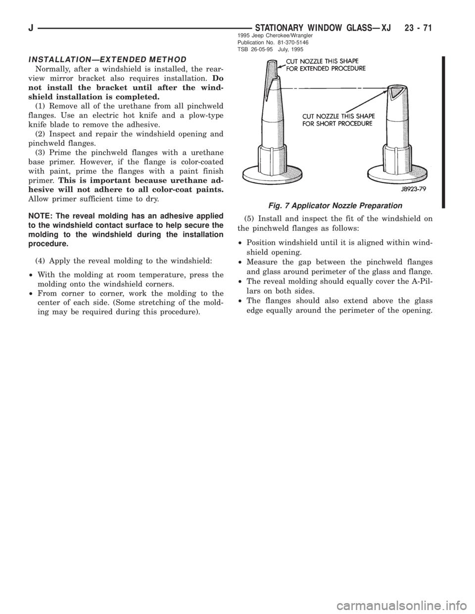
INSTALLATIONÐEXTENDED METHOD
Normally, after a windshield is installed, the rear-
view mirror bracket also requires installation.Do
not install the bracket until after the wind-
shield installation is completed.
(1) Remove all of the urethane from all pinchweld
flanges. Use an electric hot knife and a plow-type
knife blade to remove the adhesive.
(2) Inspect and repair the windshield opening and
pinchweld flanges.
(3) Prime the pinchweld flanges with a urethane
base primer. However, if the flange is color-coated
with paint, prime the flanges with a paint finish
primer.This is important because urethane ad-
hesive will not adhere to all color-coat paints.
Allow primer sufficient time to dry.
NOTE: The reveal molding has an adhesive applied
to the windshield contact surface to help secure the
molding to the windshield during the installation
procedure.
(4) Apply the reveal molding to the windshield:
²With the molding at room temperature, press the
molding onto the windshield corners.
²From corner to corner, work the molding to the
center of each side. (Some stretching of the mold-
ing may be required during this procedure).(5) Install and inspect the fit of the windshield on
the pinchweld flanges as follows:
²Position windshield until it is aligned within wind-
shield opening.
²
Measure the gap between the pinchweld flanges
and glass around perimeter of the glass and flange.
²The reveal molding should equally cover the A-Pil-
lars on both sides.
²The flanges should also extend above the glass
edge equally around the perimeter of the opening.
Fig. 7 Applicator Nozzle Preparation
JSTATIONARY WINDOW GLASSÐXJ 23 - 711995 Jeep Cherokee/Wrangler
Publication No. 81-370-5146
TSB 26-05-95 July, 1995
Page 1805 of 2198
(6) If the pinchweld flanges require repair, remove
the windshield glass and straighten, align, or repair
the flange(s) as necessary.
(7) Position the windshield in the opening and in-
spect the windshield fit again. Mark the windshield
final position on the glass and body with a wax pen-
cil (or use masking tape). The marks (or masking
tape) will be used for installation alignment refer-
ence.
(8) If the replacement windshield does not have
blackout primer:
²Attach a 25-mm (1-in) wide masking tape band
around the interior side of glass 16 mm (5/8 in)
from edge of glass (Fig. 2).
²Do not attach tape along the bottom of the glass
and attach only to the inside of glass.
²Thoroughly mix and apply blackout primer to the
16 mm (5/8 in) surface area around the interior
side of the glass (Fig. 4).
²Allow the primer to dry for at least 10-12 minutes.
(9) Apply a small amount of adhesive to the bot-
tom support spacers and attach the support spacers
to the bottom of the windshield, 170 mm inboard
from the outer windshield edge (Fig. 6).
(10) Cut the urethane applicator nozzle (Fig. 7).
(11) Apply a continuous bead of urethane to the
surface area with blackout primer on the interior
side of glass. The bead should be 9-mm (3/8-in) wide
by 12.7-mm (1/2-in) deep for best results.CAUTION: Be prepared to install the windshield im-
mediately after applying the adhesive, as the adhe-
sive will begin to cure in less than 10 minutes.
(12) Align the windshield with the wax pencil in-
stallation alignment reference marks (or the tape
strips). Position the windshield on pinchweld flanges
and spacers.
(13) Force the windshield inward just enough to
wet-out and set the urethane. Use care to avoid ex-
cessive squeeze-out of adhesive.
(14) Water test the windshield with a water spray
after installation. Do not direct high pressure
streams of water directly at the urethane. If any
leaks are detected, apply urethane as necessary.
(15) If used, remove the masking tape from the in-
ner surface of glass.
(16) Install all components and clean the vehicle. If
necessary, refer to the installation procedures.
(17) Open the vehicle windows to prevent interior
pressure while the urethane adhesive is curing.If
not vented, pressure in the interior of vehicle
will interfere with glass bonding.
(18) Install the rearview mirror on the bracket.
REAR DOOR STATIONARY WINDOW GLASS
REMOVAL
(1) Lower the window glass.
(2) Pry the window beltline molding away from the
clips and remove the molding from the door.
(3) Remove the window weatherstrip seals from
the door.
23 - 72 STATIONARY WINDOW GLASSÐXJJ1995 Jeep Cherokee/Wrangler
Publication No. 81-370-5146
TSB 26-05-95 July, 1995
Page 1806 of 2198
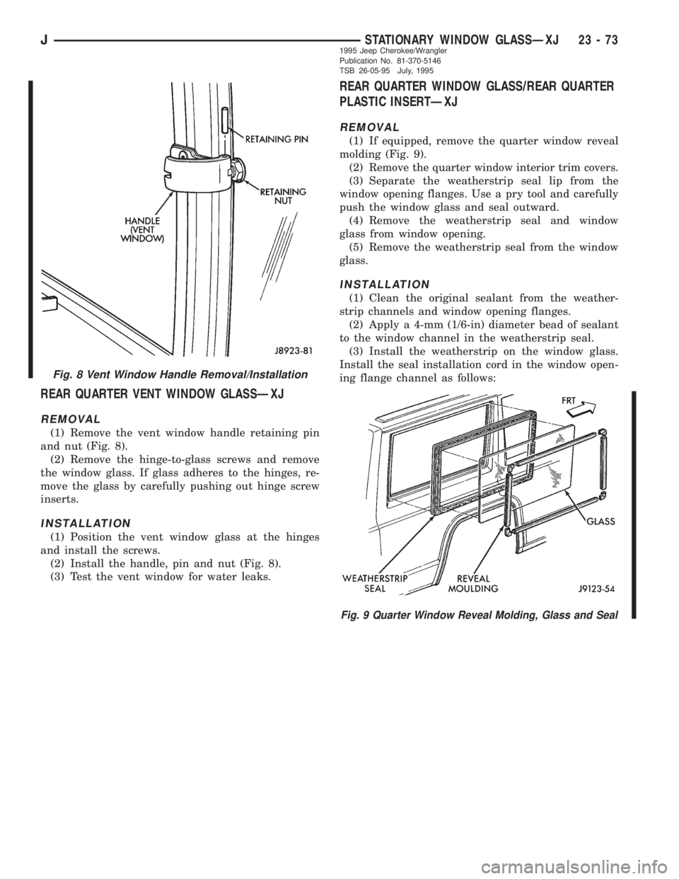
REAR QUARTER VENT WINDOW GLASSÐXJ
REMOVAL
(1) Remove the vent window handle retaining pin
and nut (Fig. 8).
(2) Remove the hinge-to-glass screws and remove
the window glass. If glass adheres to the hinges, re-
move the glass by carefully pushing out hinge screw
inserts.
INSTALLATION
(1) Position the vent window glass at the hinges
and install the screws.
(2) Install the handle, pin and nut (Fig. 8).
(3) Test the vent window for water leaks.
REAR QUARTER WINDOW GLASS/REAR QUARTER
PLASTIC INSERTÐXJ
REMOVAL
(1) If equipped, remove the quarter window reveal
molding (Fig. 9).
(2)
Remove the quarter window interior trim covers.
(3) Separate the weatherstrip seal lip from the
window opening flanges. Use a pry tool and carefully
push the window glass and seal outward.
(4) Remove the weatherstrip seal and window
glass from window opening.
(5) Remove the weatherstrip seal from the window
glass.
INSTALLATION
(1) Clean the original sealant from the weather-
strip channels and window opening flanges.
(2) Apply a 4-mm (1/6-in) diameter bead of sealant
to the window channel in the weatherstrip seal.
(3) Install the weatherstrip on the window glass.
Install the seal installation cord in the window open-
ing flange channel as follows:
Fig. 8 Vent Window Handle Removal/Installation
Fig. 9 Quarter Window Reveal Molding, Glass and Seal
JSTATIONARY WINDOW GLASSÐXJ 23 - 731995 Jeep Cherokee/Wrangler
Publication No. 81-370-5146
TSB 26-05-95 July, 1995
Page 1807 of 2198
²Moisten a length of 6-mm (1/4-in) diameter cord
with a soap and water solution.
²Ensure that the cord is long enough to go all the
way around the perimeter of the weatherstrip.
²Insert the cord into the window opening flange
channel in the weatherstrip seal.
(4) Apply a 6-mm (1/4-in) diameter bead of sealant
to the window opening flanges.
(5) For two-door vehicles, apply a 3-mm (1/8-in) di-
ameter bead of sealant at the quarter panel applique
and liftgate pillar seam.
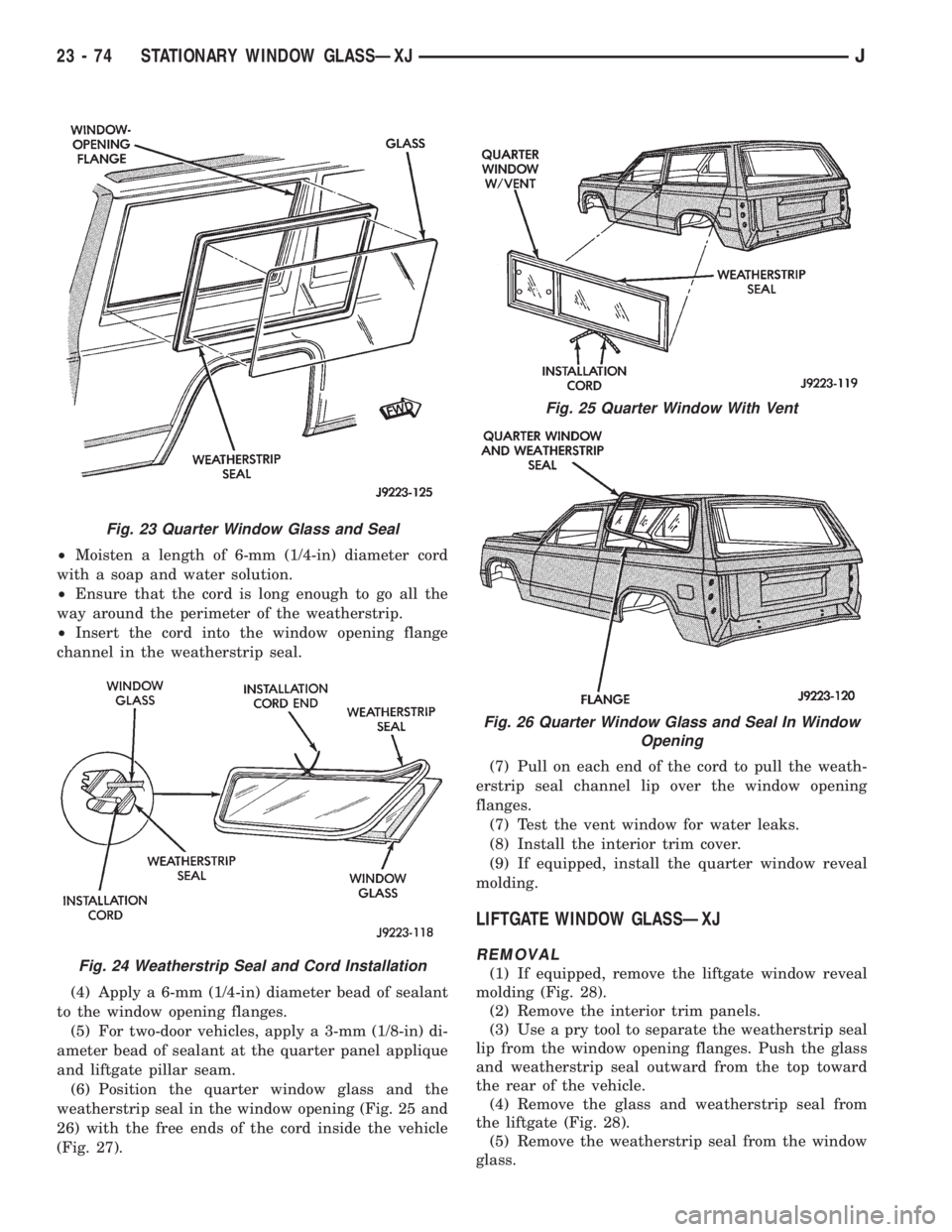
(6) Position the quarter window glass and the
weatherstrip seal in the window opening (Fig. 25 and
26) with the free ends of the cord inside the vehicle
(Fig. 27).(7) Pull on each end of the cord to pull the weath-
erstrip seal channel lip over the window opening
flanges.
(7) Test the vent window for water leaks.
(8) Install the interior trim cover.
(9) If equipped, install the quarter window reveal
molding.
LIFTGATE WINDOW GLASSÐXJ
REMOVAL
(1) If equipped, remove the liftgate window reveal
molding (Fig. 28).
(2) Remove the interior trim panels.
(3) Use a pry tool to separate the weatherstrip seal
lip from the window opening flanges. Push the glass
and weatherstrip seal outward from the top toward
the rear of the vehicle.
(4) Remove the glass and weatherstrip seal from
the liftgate (Fig. 28).
(5) Remove the weatherstrip seal from the window
glass.
Fig. 23 Quarter Window Glass and Seal
Fig. 24 Weatherstrip Seal and Cord Installation
Fig. 25 Quarter Window With Vent
Fig. 26 Quarter Window Glass and Seal In Window
Opening
23 - 74 STATIONARY WINDOW GLASSÐXJJ
Page 1808 of 2198
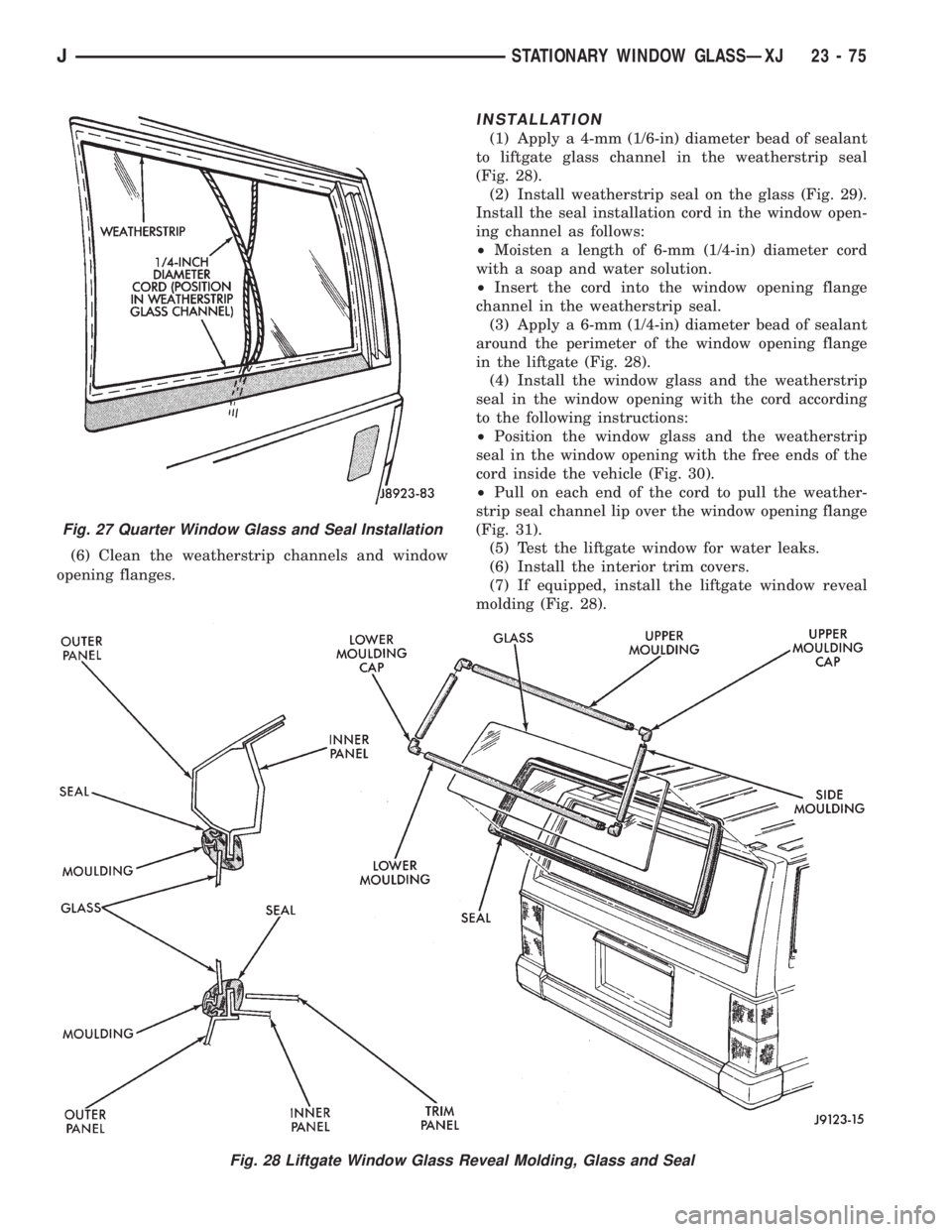
(6) Clean the weatherstrip channels and window
opening flanges.
INSTALLATION
(1) Apply a 4-mm (1/6-in) diameter bead of sealant
to liftgate glass channel in the weatherstrip seal
(Fig. 28).
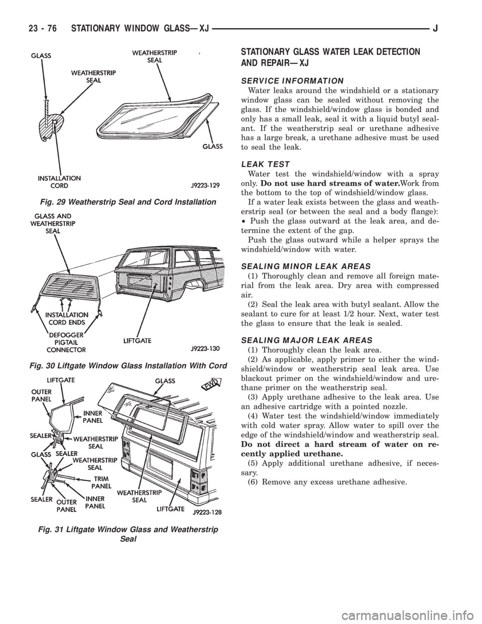
(2) Install weatherstrip seal on the glass (Fig. 29).
Install the seal installation cord in the window open-
ing channel as follows:
²Moisten a length of 6-mm (1/4-in) diameter cord
with a soap and water solution.
²Insert the cord into the window opening flange
channel in the weatherstrip seal.
(3) Apply a 6-mm (1/4-in) diameter bead of sealant
around the perimeter of the window opening flange
in the liftgate (Fig. 28).
(4) Install the window glass and the weatherstrip
seal in the window opening with the cord according
to the following instructions:
²Position the window glass and the weatherstrip
seal in the window opening with the free ends of the
cord inside the vehicle (Fig. 30).
²Pull on each end of the cord to pull the weather-
strip seal channel lip over the window opening flange
(Fig. 31).
(5) Test the liftgate window for water leaks.
(6) Install the interior trim covers.
(7) If equipped, install the liftgate window reveal
molding (Fig. 28).
Fig. 28 Liftgate Window Glass Reveal Molding, Glass and Seal
Fig. 27 Quarter Window Glass and Seal Installation
JSTATIONARY WINDOW GLASSÐXJ 23 - 75
Page 1809 of 2198
STATIONARY GLASS WATER LEAK DETECTION
AND REPAIRÐXJ
SERVICE INFORMATION
Water leaks around the windshield or a stationary
window glass can be sealed without removing the
glass. If the windshield/window glass is bonded and
only has a small leak, seal it with a liquid butyl seal-
ant. If the weatherstrip seal or urethane adhesive
has a large break, a urethane adhesive must be used
to seal the leak.
LEAK TEST
Water test the windshield/window with a spray
only.Do not use hard streams of water.Work from
the bottom to the top of windshield/window glass.
If a water leak exists between the glass and weath-
erstrip seal (or between the seal and a body flange):
²Push the glass outward at the leak area, and de-
termine the extent of the gap.
Push the glass outward while a helper sprays the
windshield/window with water.
SEALING MINOR LEAK AREAS
(1) Thoroughly clean and remove all foreign mate-
rial from the leak area. Dry area with compressed
air.
(2) Seal the leak area with butyl sealant. Allow the
sealant to cure for at least 1/2 hour. Next, water test
the glass to ensure that the leak is sealed.
SEALING MAJOR LEAK AREAS
(1) Thoroughly clean the leak area.
(2) As applicable, apply primer to either the wind-
shield/window or weatherstrip seal leak area. Use
blackout primer on the windshield/window and ure-
thane primer on the weatherstrip seal.
(3) Apply urethane adhesive to the leak area. Use
an adhesive cartridge with a pointed nozzle.
(4) Water test the windshield/window immediately
with cold water spray. Allow water to spill over the
edge of the windshield/window and weatherstrip seal.
Do not direct a hard stream of water on re-
cently applied urethane.
(5) Apply additional urethane adhesive, if neces-
sary.
(6) Remove any excess urethane adhesive.
Fig. 29 Weatherstrip Seal and Cord Installation
Fig. 30 Liftgate Window Glass Installation With Cord
Fig. 31 Liftgate Window Glass and Weatherstrip
Seal
23 - 76 STATIONARY WINDOW GLASSÐXJJ
Page 1835 of 2198
BODY COMPONENTSÐYJ VEHICLES
CONTENTS
page page
DOORS............................... 134
EXTERIOR COMPONENTS................ 104
GENERAL SERVICE INFORMATION......... 102INTERIOR COMPONENTS................ 151
PAINT................................ 158
STATIONARY GLASS.................... 144
GENERAL SERVICE INFORMATION
LABELS/DECALS/PLATESÐYJ
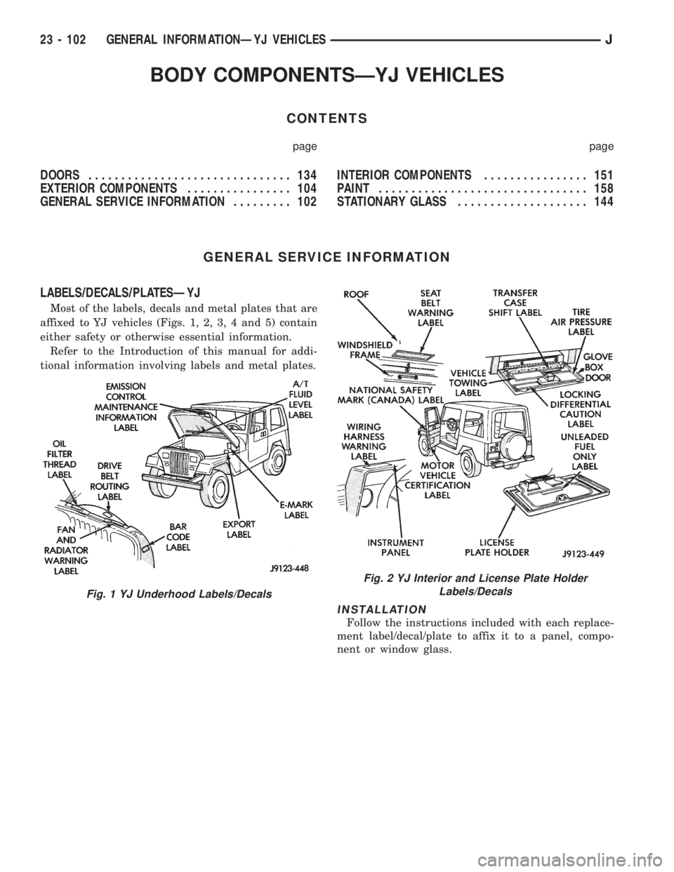
Most of the labels, decals and metal plates that are
affixed to YJ vehicles (Figs. 1, 2, 3, 4 and 5) contain
either safety or otherwise essential information.
Refer to the Introduction of this manual for addi-
tional information involving labels and metal plates.
INSTALLATION
Follow the instructions included with each replace-
ment label/decal/plate to affix it to a panel, compo-
nent or window glass.
Fig. 1 YJ Underhood Labels/Decals
Fig. 2 YJ Interior and License Plate Holder
Labels/Decals
23 - 102 GENERAL INFORMATIONÐYJ VEHICLESJ
Page 1858 of 2198
(8) Separate the liftgate glass from the hard top.
(9) Remove the weatherstrip seal (Fig. 2), if neces-
sary.
INSTALLATION
(1) Assemble the liftgate components, if necessary
(2) Position the liftgate glass in the hard top open-
ing and install the hinge bolts. Do not tighten the
bolts.
(3) Adjust the liftgate glass to fit the hard top
opening.
(4) Tighten the hinge bolts to 11 Nzm (95 in-lbs)
torque.
(5) Position the support rod cylinders on the ball
studs.
(6) Install the support rod cylinder retainer clips.
(7) Connect the wiper motor wire harness connec-
tor and the washer fluid hose. Install the wiper mo-
tor cover (Fig. 1).
(8) Install the wiper arm and blade.
(9) Connect the rear window defroster/dome lamp
wire harness connectors.
DISASSEMBLY
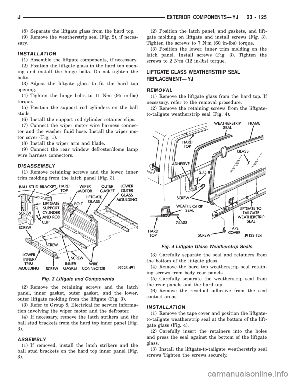
(1) Remove retaining screws and the lower, inner
trim molding from the latch panel (Fig. 3).
(2) Remove the retaining screws and the latch
panel, inner gasket, outer gasket, and the lower,
outer liftgate molding from the liftgate (Fig. 3).
(3) Refer to Group 8, Electrical for service informa-
tion involving the wiper motor and the defroster.
(4) If necessary, remove the latch strikers and the
ball stud brackets from the hard top inner panel (Fig.
3).
ASSEMBLY
(1) If removed, install the latch strikers and the
ball stud brackets on the hard top inner panel (Fig.
3).(2) Position the latch panel, and gaskets, and lift-
gate molding on liftgate and install screws (Fig. 3).
Tighten the screws to 7 Nzm (60 in-lbs) torque.
(3) Position the lower, inner trim molding on the
latch panel. Install screws (Fig. 3). Tighten the
screws to 2 Nzm (12 in-lbs) torque.
LIFTGATE GLASS WEATHERSTRIP SEAL
REPLACEMENTÐYJ
REMOVAL
(1) Remove the liftgate glass from the hard top. If
necessary, refer to the removal procedure.
(2) Remove the retaining screws from the liftgate-
to-tailgate weatherstrip seal (Fig. 4).
(3) Carefully separate the seal and retainers from
the bottom of the liftgate glass.
(4) Remove the hard top weatherstrip seal retain-
ing screws from body rear panels.
(5) Carefully separate the weatherstrip seal from
the rear panels and the hard top.
(6) Remove the residual adhesive from the seal
contact areas.
INSTALLATION
(1) Remove the tape cover and position the liftgate-
to-tailgate weatherstrip seal at the bottom of the lift-
gate glass (Fig. 4).
(2) Carefully insert the retainers into the holes
and press the seal against the bottom of the liftgate
glass.
(3) Install the liftgate-to-tailgate weatherstrip seal
screws Tighten the screws securely.
Fig. 3 Liftgate and Components
Fig. 4 Liftgate Glass Weatherstrip Seals
JEXTERIOR COMPONENTSÐYJ 23 - 125