1995 JEEP CHEROKEE window
[x] Cancel search: windowPage 964 of 2198
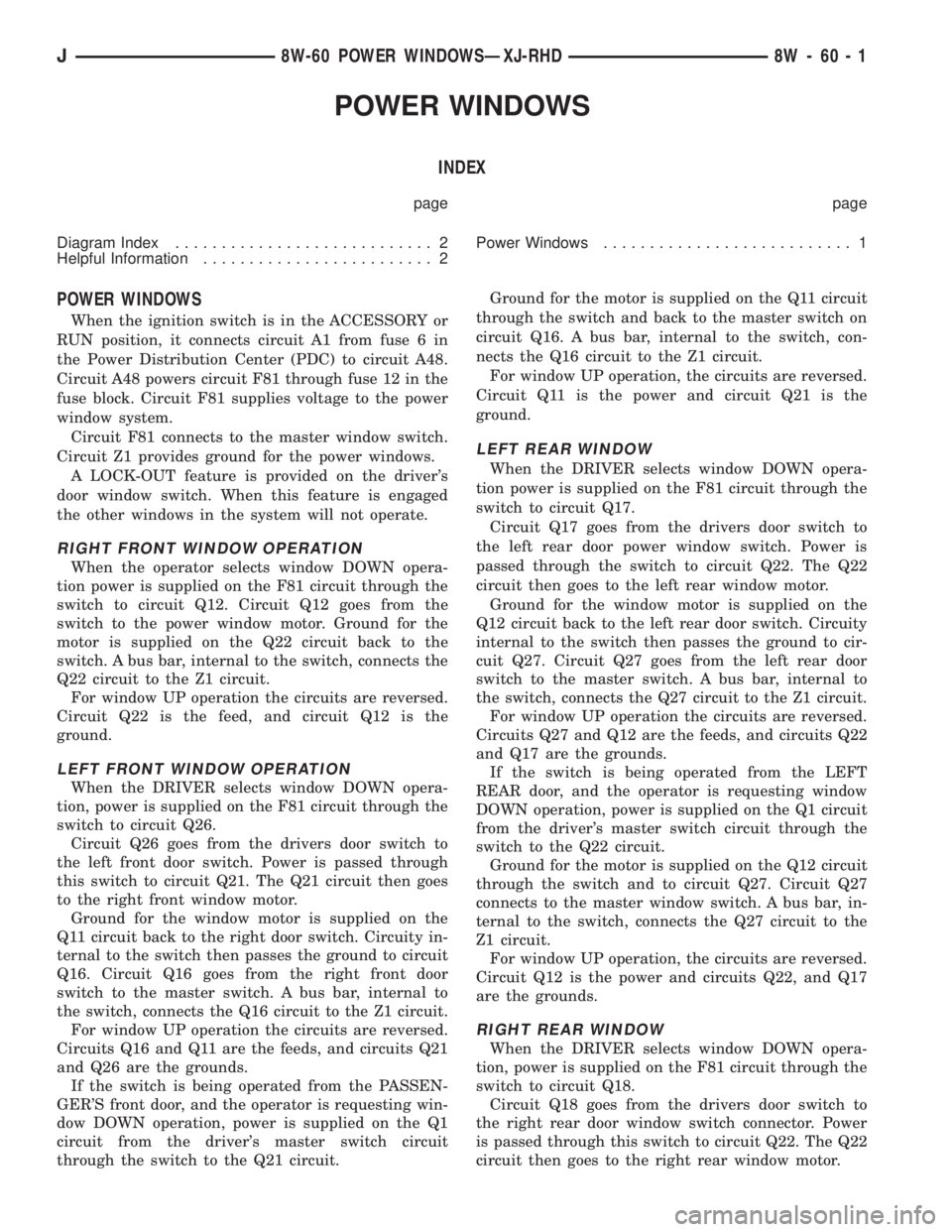
POWER WINDOWS
INDEX
page page
Diagram Index............................ 2
Helpful Information......................... 2Power Windows........................... 1
POWER WINDOWS
When the ignition switch is in the ACCESSORY or
RUN position, it connects circuit A1 from fuse 6 in
the Power Distribution Center (PDC) to circuit A48.
Circuit A48 powers circuit F81 through fuse 12 in the
fuse block. Circuit F81 supplies voltage to the power
window system.
Circuit F81 connects to the master window switch.
Circuit Z1 provides ground for the power windows.
A LOCK-OUT feature is provided on the driver's
door window switch. When this feature is engaged
the other windows in the system will not operate.
RIGHT FRONT WINDOW OPERATION
When the operator selects window DOWN opera-
tion power is supplied on the F81 circuit through the
switch to circuit Q12. Circuit Q12 goes from the
switch to the power window motor. Ground for the
motor is supplied on the Q22 circuit back to the
switch. A bus bar, internal to the switch, connects the
Q22 circuit to the Z1 circuit.
For window UP operation the circuits are reversed.
Circuit Q22 is the feed, and circuit Q12 is the
ground.
LEFT FRONT WINDOW OPERATION
When the DRIVER selects window DOWN opera-
tion, power is supplied on the F81 circuit through the
switch to circuit Q26.
Circuit Q26 goes from the drivers door switch to
the left front door switch. Power is passed through
this switch to circuit Q21. The Q21 circuit then goes
to the right front window motor.
Ground for the window motor is supplied on the
Q11 circuit back to the right door switch. Circuity in-
ternal to the switch then passes the ground to circuit
Q16. Circuit Q16 goes from the right front door
switch to the master switch. A bus bar, internal to
the switch, connects the Q16 circuit to the Z1 circuit.
For window UP operation the circuits are reversed.
Circuits Q16 and Q11 are the feeds, and circuits Q21
and Q26 are the grounds.
If the switch is being operated from the PASSEN-
GER'S front door, and the operator is requesting win-
dow DOWN operation, power is supplied on the Q1
circuit from the driver's master switch circuit
through the switch to the Q21 circuit.Ground for the motor is supplied on the Q11 circuit
through the switch and back to the master switch on
circuit Q16. A bus bar, internal to the switch, con-
nects the Q16 circuit to the Z1 circuit.
For window UP operation, the circuits are reversed.
Circuit Q11 is the power and circuit Q21 is the
ground.
LEFT REAR WINDOW
When the DRIVER selects window DOWN opera-
tion power is supplied on the F81 circuit through the
switch to circuit Q17.
Circuit Q17 goes from the drivers door switch to
the left rear door power window switch. Power is
passed through the switch to circuit Q22. The Q22
circuit then goes to the left rear window motor.
Ground for the window motor is supplied on the
Q12 circuit back to the left rear door switch. Circuity
internal to the switch then passes the ground to cir-
cuit Q27. Circuit Q27 goes from the left rear door
switch to the master switch. A bus bar, internal to
the switch, connects the Q27 circuit to the Z1 circuit.
For window UP operation the circuits are reversed.
Circuits Q27 and Q12 are the feeds, and circuits Q22
and Q17 are the grounds.
If the switch is being operated from the LEFT
REAR door, and the operator is requesting window
DOWN operation, power is supplied on the Q1 circuit
from the driver's master switch circuit through the
switch to the Q22 circuit.
Ground for the motor is supplied on the Q12 circuit
through the switch and to circuit Q27. Circuit Q27
connects to the master window switch. A bus bar, in-
ternal to the switch, connects the Q27 circuit to the
Z1 circuit.
For window UP operation, the circuits are reversed.
Circuit Q12 is the power and circuits Q22, and Q17
are the grounds.
RIGHT REAR WINDOW
When the DRIVER selects window DOWN opera-
tion, power is supplied on the F81 circuit through the
switch to circuit Q18.
Circuit Q18 goes from the drivers door switch to
the right rear door window switch connector. Power
is passed through this switch to circuit Q22. The Q22
circuit then goes to the right rear window motor.
J8W-60 POWER WINDOWSÐXJ-RHD 8W - 60 - 1
Page 965 of 2198
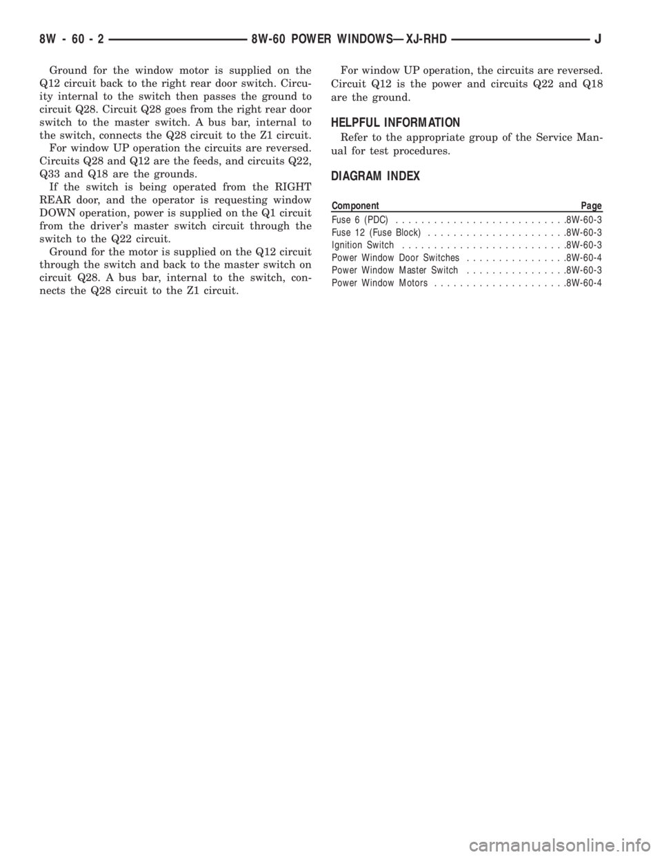
Ground for the window motor is supplied on the
Q12 circuit back to the right rear door switch. Circu-
ity internal to the switch then passes the ground to
circuit Q28. Circuit Q28 goes from the right rear door
switch to the master switch. A bus bar, internal to
the switch, connects the Q28 circuit to the Z1 circuit.
For window UP operation the circuits are reversed.
Circuits Q28 and Q12 are the feeds, and circuits Q22,
Q33 and Q18 are the grounds.
If the switch is being operated from the RIGHT
REAR door, and the operator is requesting window
DOWN operation, power is supplied on the Q1 circuit
from the driver's master switch circuit through the
switch to the Q22 circuit.
Ground for the motor is supplied on the Q12 circuit
through the switch and back to the master switch on
circuit Q28. A bus bar, internal to the switch, con-
nects the Q28 circuit to the Z1 circuit.For window UP operation, the circuits are reversed.
Circuit Q12 is the power and circuits Q22 and Q18
are the ground.
HELPFUL INFORMATION
Refer to the appropriate group of the Service Man-
ual for test procedures.
DIAGRAM INDEX
Component Page
Fuse 6 (PDC)...........................8W-60-3
Fuse 12 (Fuse Block)......................8W-60-3
Ignition Switch..........................8W-60-3
Power Window Door Switches................8W-60-4
Power Window Master Switch................8W-60-3
Power Window Motors.....................8W-60-4
8W - 60 - 2 8W-60 POWER WINDOWSÐXJ-RHDJ
Page 972 of 2198
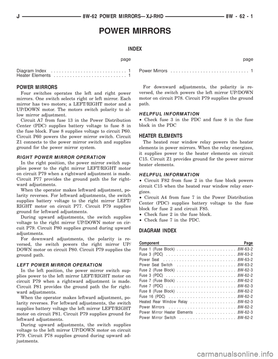
POWER MIRRORS
INDEX
page page
Diagram Index............................ 1
Heater Elements........................... 1Power Mirrors............................. 1
POWER MIRRORS
Four switches operates the left and right power
mirrors. One switch selects right or left mirror. Each
mirror has two motors; a LEFT/RIGHT motor and a
UP/DOWN motor. The motors switch polarity to al-
low mirror adjustment.
Circuit A7 from fuse 13 in the Power Distribution
Center (PDC) supplies battery voltage to fuse 8 in
the fuse block. Fuse 8 supplies voltage to circuit P60.
Circuit P60 powers the power mirror switch. Circuit
Z1 connects to the power mirror switch and supplies
ground for the power mirror system.
RIGHT POWER MIRROR OPERATION
In the right position, the power mirror switch sup-
plies power to the right mirror LEFT/RIGHT motor
on circuit P79 when a rightward adjustment is made.
Circuit P77 provides the ground path the for right-
ward adjustments.
When the operator makes leftward adjustment, po-
larity reverses. For leftward adjustments, the switch
supplies battery voltage to the right mirror LEFT/
RIGHT motor on circuit P77. Circuit P79 supplies
ground for leftward adjustments.
During upward adjustments, the switch supplies
voltage to the right mirror UP/DOWN motor on cir-
cuit P79. Circuit P80 supplies ground during upward
adjustments.
For downward adjustments, the polarity is re-
versed, the switch powers the right mirror UP/
DOWN motor on circuit P80. Circuit P79 supplies the
ground path.
LEFT POWER MIRROR OPERATION
In the left position, the power mirror switch sup-
plies power to the left mirror LEFT/RIGHT motor on
circuit P79 when a rightward adjustment is made.
Circuit P81 provides the ground path the for right-
ward adjustments.
When the operator makes leftward adjustment, po-
larity reverses. For leftward adjustments, the switch
supplies battery voltage the left mirror LEFT/RIGHT
motor on circuit P81. Circuit P79 supplies ground for
leftward adjustments.
During upward adjustments, the switch supplies
voltage to the left mirror UP/DOWN motor on circuit
P79. Circuit P78 supplies ground during upward ad-
justments.For downward adjustments, the polarity is re-
versed, the switch powers the left mirror UP/DOWN
motor on circuit P78. Circuit P79 supplies the ground
path.
HELPFUL INFORMATION
²Check fuse 3 in the PDC and fuse 8 in the fuse
block in the PDC
HEATER ELEMENTS
The heated rear window relay powers the heater
elements in power mirrors. When the relay energizes,
it supplies power to the heater elements on circuit
C15. Circuit Z1 provides ground for the power mirror
heater elements.
HELPFUL INFORMATION
²Circuit F82 from fuse 2 in the fuse block powers
circuit C15 when the heated rear window relay ener-
gizes.
²Circuit A4 from fuse 7 in the Power Distribution
Center (PDC) supplies battery voltage to the fuse
block for fuse 2 and circuit F85.
²Check fuse 2 in the fuse block.
²Check fuse 7 in the PDC.
DIAGRAM INDEX
Component Page
Fuse 1 (Fuse Block).......................8W-63-2
Fuse 3 (PDC)...........................8W-63-2
Power Seat............................8W-63-2
Power Seat Switch.......................8W-63-2
Fuse 2 (Fuse Block).......................8W-62-3
Fuse 3 (PDC)...........................8W-62-2
Fuse 7 (Fuse Block).......................8W-62-2
Fuse 7 (PDC)...........................8W-62-3
Fuse 8 (Fuse Block).......................8W-62-2
Fuse 16 (PDC)..........................8W-62-2
Heated Rear Window Relay..................8W-62-3
Power Mirrors..........................8W-62-2
Power Mirror Heater Elements................8W-62-3
Power Mirror Switch......................8W-62-2
J8W-62 POWER MIRRORSÐXJ-RHD 8W - 62 - 1
Page 1082 of 2198
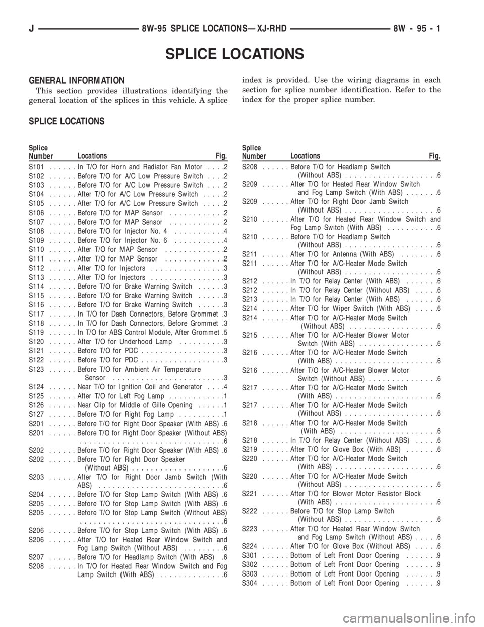
SPLICE LOCATIONS
GENERAL INFORMATION
This section provides illustrations identifying the
general location of the splices in this vehicle. A spliceindex is provided. Use the wiring diagrams in each
section for splice number identification. Refer to the
index for the proper splice number.
SPLICE LOCATIONS
Splice
NumberLocations Fig.
S101......InT/OforHorn and Radiator Fan Motor....2
S102......Before T/O for A/C Low Pressure Switch....2
S103......Before T/O for A/C Low Pressure Switch....2
S104......After T/O for A/C Low Pressure Switch.....2
S105......After T/O for A/C Low Pressure Switch.....2
S106......Before T/O for MAP Sensor............2
S107......Before T/O for MAP Sensor............2
S108......Before T/O for Injector No. 4...........4
S109......Before T/O for Injector No. 6...........4
S110......After T/O for MAP Sensor.............2
S111......After T/O for MAP Sensor.............2
S112......After T/O for Injectors................3
S113......After T/O for Injectors................3
S114......Before T/O for Brake Warning Switch......3
S115......Before T/O for Brake Warning Switch......3
S116......Before T/O for Brake Warning Switch......3
S117......InT/OforDash Connectors, Before Grommet .3
S118......InT/OforDash Connectors, Before Grommet .3
S119......InT/OforABSControl Module, After Grommet .5
S120......After T/O for Underhood Lamp..........3
S121......Before T/O for PDC..................3
S122......Before T/O for PDC..................3
S123......Before T/O for Ambient Air Temperature
Sensor........................3
S124......Near T/O for Ignition Coil and Generator....4
S125......After T/O for Left Fog Lamp............1
S126......Near Clip for Middle of Gille Opening......1
S127......Before T/O for Right Fog Lamp..........1
S201......Before T/O for Right Door Speaker (With ABS) .6
S201......Before T/O for Right Door Speaker (Without ABS)
...............................6
S202......Before T/O for Right Door Speaker (With ABS) .6
S202......Before T/O for Right Door Speaker
(Without ABS)....................6
S203......After T/O for Right Door Jamb Switch (With
ABS)...........................6
S204......Before T/O for Stop Lamp Switch (With ABS) .6
S205......Before T/O for Stop Lamp Switch (With ABS) .6
S205......Before T/O for Stop Lamp Switch (Without ABS)
...............................6
S206......Before T/O for Stop Lamp Switch (With ABS) .6
S206......After T/O for Heated Rear Window Switch and
Fog Lamp Switch (Without ABS).........6
S207......Before T/O for Headlamp Switch (With ABS) .6
S208......InT/OforHeated Rear Window Switch and Fog
Lamp Switch (With ABS)..............6Splice
NumberLocations Fig.
S208......Before T/O for Headlamp Switch
(Without ABS)....................6
S209......After T/O for Heated Rear Window Switch
and Fog Lamp Switch (With ABS).......6
S209......After T/O for Right Door Jamb Switch
(Without ABS)....................6
S210......After T/O for Heated Rear Window Switch and
Fog Lamp Switch (With ABS)...........6
S210......Before T/O for Headlamp Switch
(Without ABS)....................6
S211......After T/O for Antenna (With ABS)........6
S211......After T/O for A/C-Heater Mode Switch
(Without ABS)....................6
S212......InT/OforRelay Center (With ABS).......6
S212......InT/OforRelay Center (Without ABS).....6
S213......InT/OforRelay Center (With ABS).......6
S214......After T/O for Wiper Switch (With ABS).....6
S214......After T/O for A/C-Heater Mode Switch
(Without ABS)...................6
S215......After T/O for A/C-Heater Blower Motor
Switch (With ABS).................6
S216......After T/O for A/C-Heater Mode Switch
(With ABS)......................6
S216......After T/O for A/C-Heater Blower Motor
Switch (Without ABS)...............6
S217......After T/O for A/C-Heater Mode Switch
(With ABS)......................6
S217......After T/O for A/C-Heater Mode Switch
(Without ABS)....................6
S218......After T/O for A/C-Heater Mode Switch
(With ABS).....................6
S218......InT/OforRelay Center (Without ABS).....6
S219......After T/O for Glove Box (With ABS).......6
S220......After T/O for A/C-Heater Mode Switch
(With ABS)......................6
S220......After T/O for A/C-Heater Mode Switch
(Without ABS)....................6
S221......After T/O for Blower Motor Resistor Block
(With ABS)......................6
S222......Before T/O for Stop Lamp Switch
(Without ABS)....................6
S223......After T/O for Heated Rear Window Switch
and Fog Lamp Switch (Without ABS).....6
S224......After T/O for Glove Box (Without ABS).....6
S301......Bottom of Left Front Door Opening.......9
S302......Bottom of Left Front Door Opening.......9
S303......Bottom of Left Front Door Opening.......9
S304......Bottom of Left Front Door Opening.......9
J8W-95 SPLICE LOCATIONSÐXJ-RHD 8W - 95 - 1
Page 1348 of 2198
AIRBAG MODULE REMOVEÐINSTALL
WARNING: THIS AIRBAG SYSTEM IS A SENSITIVE,
COMPLEX MECHANICAL UNIT. BEFORE ATTEMPT-
ING TO REMOVE OR INSTALL THE AIRBAG SYS-
TEM OR RELATED STEERING WHEEL AND
STEERING COLUMN COMPONENTS YOU MUST
FIRST DISARM THE AIRBAG FIRING MECHANISM.
FAILURE TO DO SO COULD RESULT IN ACCIDEN-
TAL DEPLOYMENT AND POSSIBLE PERSONAL IN-
JURY.
When removing a deployed airbag module,
rubber gloves, eye protection and long-sleeved
shirt should be worn. There may be deposits on
the airbag module and other interior surfaces,
which can cause irritation to the skin and eyes
in large doses.
(1) Disconnect battery negative cable and isolate.
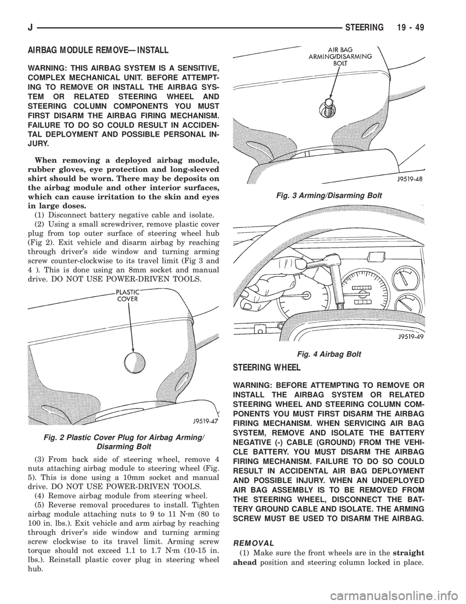
(2) Using a small screwdriver, remove plastic cover
plug from top outer surface of steering wheel hub
(Fig 2). Exit vehicle and disarm airbag by reaching
through driver's side window and turning arming
screw counter-clockwise to its travel limit (Fig 3 and
4 ). This is done using an 8mm socket and manual
drive. DO NOT USE POWER-DRIVEN TOOLS.
(3) From back side of steering wheel, remove 4
nuts attaching airbag module to steering wheel (Fig.
5). This is done using a 10mm socket and manual
drive. DO NOT USE POWER-DRIVEN TOOLS.
(4) Remove airbag module from steering wheel.
(5) Reverse removal procedures to install. Tighten
airbag module attaching nuts to 9 to 11 Nzm (80 to
100 in. lbs.). Exit vehicle and arm airbag by reaching
through driver's side window and turning arming
screw clockwise to its travel limit. Arming screw
torque should not exceed 1.1 to 1.7 Nzm (10-15 in.
lbs.). Reinstall plastic cover plug in steering wheel
hub.
STEERING WHEEL
WARNING: BEFORE ATTEMPTING TO REMOVE OR
INSTALL THE AIRBAG SYSTEM OR RELATED
STEERING WHEEL AND STEERING COLUMN COM-
PONENTS YOU MUST FIRST DISARM THE AIRBAG
FIRING MECHANISM. WHEN SERVICING AIR BAG
SYSTEM, REMOVE AND ISOLATE THE BATTERY
NEGATIVE (-) CABLE (GROUND) FROM THE VEHI-
CLE BATTERY. YOU MUST DISARM THE AIRBAG
FIRING MECHANISM. FAILURE TO DO SO COULD
RESULT IN ACCIDENTAL AIR BAG DEPLOYMENT
AND POSSIBLE INJURY. WHEN AN UNDEPLOYED
AIR BAG ASSEMBLY IS TO BE REMOVED FROM
THE STEERING WHEEL, DISCONNECT THE BAT-
TERY GROUND CABLE AND ISOLATE. THE ARMING
SCREW MUST BE USED TO DISARM THE AIRBAG.
REMOVAL
(1) Make sure the front wheels are in thestraight
aheadposition and steering column locked in place.
Fig. 2 Plastic Cover Plug for Airbag Arming/
Disarming Bolt
Fig. 3 Arming/Disarming Bolt
Fig. 4 Airbag Bolt
JSTEERING 19 - 49
Page 1734 of 2198
BODY COMPONENTSÐXJ VEHICLES
CONTENTS
page page
DOORS................................ 30
EXTERIOR COMPONENTS.................. 3
GENERAL BODY SERVICE INFORMATION..... 1INTERIOR COMPONENTS................. 80
STATIONARY WINDOW GLASS............. 66
TRAILER HITCH......................... 77
GENERAL BODY SERVICE INFORMATION
RIGHT HAND DRIVE VEHICLES
The XJ Body Components procedures in this sec-
tion were developed on a left hand drive (LHD) vehi-
cle. Unless a component is unique to a right hand
drive vehicle, it will not be specifically covered in this
section, i.e. cargo barrier. In general, components on
left hand drive vehicles will be located on the oppo-
site side in right hand drive vehicles.
LABELS/DECALS/PLATESÐXJ
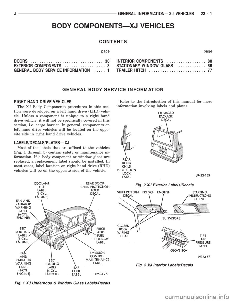
Most of the labels that are affixed to the vehicles
(Fig. 1 through 5) contain safety or maintenance in-
formation. If a body component or window glass are
replaced, a replacement label should be installed. In
most cases, label location on right hand drive (RHD)
vehicles will be on the opposite side of the vehicle.Refer to the Introduction of this manual for more
information involving labels and plates.
Fig. 1 XJ Underhood & Window Glass Labels/Decals
Fig. 2 XJ Exterior Labels/Decals
Fig. 3 XJ Interior Labels/Decals
JGENERAL INFORMATIONÐXJ VEHICLES 23 - 1
Page 1736 of 2198
EXTERIOR COMPONENTS
INDEX
page page
Air Exhaust GrilleÐXJ...................... 25
Battery TrayÐXJ.......................... 14
Body Side Molding/CladdingÐXJ.............. 20
Body Stripes/DecalsÐXJ.................... 21
Brush GuardÐXJ.......................... 3
Cowl Grille and ScreenÐXJ................. 12
Cowl Weatherstrip Seal/Crossmember Air
DeflectorÐXJ........................... 11
Dash Panel Insulator PanelÐXJ.............. 12
Drip Rail MoldingÐXJ...................... 25
Exterior NameplatesÐXJ................... 26
External MirrorsÐXJ....................... 27
Front FenderÐXJ......................... 14
Fuel Filler Door BumpersÐXJ................ 27Fuel Filler Nozzle/TubeÐXJ................. 26
Grille and Grille Opening Panel (GOP)ÐXJ....... 3
Hood AdjustmentÐXJ...................... 10
Hood Hinge ReplacementÐXJ............... 10
Hood Latch ReplacementÐXJ................ 11
Hood Latch Striker ReplacementÐXJ.......... 11
HoodÐXJ................................ 7
Latch Release Cable ReplacementÐXJ......... 11
Luggage RackÐXJ........................ 28
Quarter Window AppliqueÐXJ................ 25
Radiator Support CrossmemberÐXJ............ 6
Rear Wheelhouse Flares and LinersÐXJ........ 19
Safety Latch Striker ReplacementÐXJ.......... 11
BRUSH GUARDÐXJ
REMOVAL
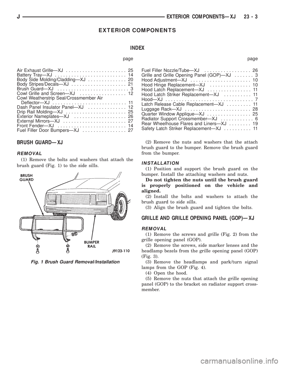
(1) Remove the bolts and washers that attach the
brush guard (Fig. 1) to the side sills.(2) Remove the nuts and washers that the attach
brush guard to the bumper. Remove the brush guard
from the bumper.INSTALLATION
(1) Position and support the brush guard on the
bumper. Install the attaching washers and nuts.
Do not tighten the nuts until the brush guard
is properly positioned on the vehicle and
aligned.
(2) Install the bolts and washers to attach the
brush guard to side sills.
(3) Align the brush guard and tighten the bolts.
GRILLE AND GRILLE OPENING PANEL (GOP)ÐXJ
REMOVAL
(1) Remove the screws and grille (Fig. 2) from the
grille opening panel (GOP).
(2) Remove the screws, side marker lenses and the
headlamp bezels from the grille opening panel (GOP)
(Fig. 3).
(3) Remove the headlamps and park/turn signal
lamps from the GOP (Fig. 4).
(4) Open the hood.
(5) Remove the nuts that attach the grille opening
panel (GOP) to the bracket on radiator support cross-
member.
Fig. 1 Brush Guard Removal/Installation
JEXTERIOR COMPONENTSÐXJ 23 - 3
Page 1758 of 2198
(3) Retain the tape stripe/decal firmly against flat
surface and separate the carrier from tape stripe/de-
cal.
(4) Use a sponge and apply solution to the tape
stripe/decal adhesive and to panel surface.
(5) Position the adhesive side of tape stripe/decal
on the panel with the bottom aligned with the char-
acter line.
²Align the end of the replacement tape stripe/decal
with the end of existing tape stripe/decal.
²Correctly align the index darts and index notches.
(6) If a complete replacement tape stripe/decal is
not being installed:
²Position the replacement tape stripe/decal section
at the center of the repair area.
²Align it with the existing tape stripe/decal.
²Allow at least 12 mm (1/2 in) of the tape stripe/de-
cal section to overlap the tape stripe/decal edges.
(7) Apply the wetting solution to the outer side of
the tape stripe/decal.
CAUTION: Avoid unnecessary pulling and stretch-
ing at the ends.
(8) Slide a squeegee from the center to the ends of
the tape stripe/decal. Use firm strokes to remove all
of the air bubbles.
(9) If a wrinkle is trapped in the tape stripe/decal
stop immediately. Lift the wrinkled area and re-align
it with the character line to remove the wrinkle.Do
not lift the tape stripe/decal if only a few air
bubbles exist.
(10) Where applicable, allow 12 mm (1/2 in) extra
tape stripe/decal to extend beyond edges.
(11) Fold the excess tape onto the inside flange and
adhere it with finger pressure.
(12) Inspect the tape stripe/decal installation with
the reflected light to find any damage.
(13) Remove all the air and moisture bubbles from
the tape stripe/decal with a needle or pin.
(14) Install any removed components and clean the
vehicle as necessary.
QUARTER WINDOW APPLIQUEÐXJ
REMOVAL/INSTALLATION
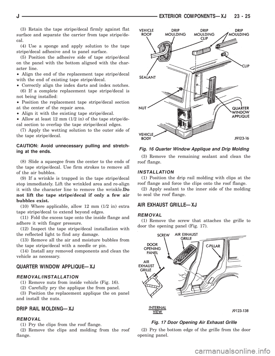
(1) Remove nuts from inside vehicle (Fig. 16).
(2) Carefully pry the applique the from panel.
(3) Position the replacement applique the on panel
and install the nuts.
DRIP RAIL MOLDINGÐXJ
REMOVAL
(1) Pry the clips from the roof flange.
(2) Remove the clips and molding from the roof
flange.(3) Remove the remaining sealant and clean the
roof flange.
INSTALLATION
(1) Position the drip rail molding with clips at the
roof flange and force the clips onto the roof flange.
(2) Apply sealant to the inner side of the molding
to seal the roof flange.
AIR EXHAUST GRILLEÐXJ
REMOVAL
(1) Remove the screw that attaches the grille to
door the opening panel (Fig. 17).
(2) Pry the bottom edge of the grille from the door
opening panel.
Fig. 16 Quarter Window Applique and Drip Molding
Fig. 17 Door Opening Air Exhaust Grille
JEXTERIOR COMPONENTSÐXJ 23 - 25