1995 JEEP CHEROKEE window
[x] Cancel search: windowPage 272 of 2198
ELECTRICAL
GROUP INDEX
Group Group
AUDIO SYSTEMS........................ 8F
BATTERY/STARTER/GENERATOR SERVICE.... 8B
BATTERY/STARTING/CHARGING SYSTEMS
DIAGNOSTICS......................... 8A
CHIME/BUZZER WARNING SYSTEMS........ 8U
HORNS................................ 8G
IGNITION SYSTEMS...................... 8D
INSTRUMENT PANEL AND GAUGES......... 8E
LAMPS................................ 8L
OVERHEAD CONSOLE.................... 8C
POWER LOCKS.......................... 8P
POWER MIRRORS....................... 8TPOWER SEATS.......................... 8R
POWER WINDOWS....................... 8S
REAR WINDOW DEFOGGER............... 8N
RESTRAINT SYSTEMS................... 8M
TURN SIGNAL AND HAZARD WARNING
SYSTEMS............................. 8J
VEHICLE SPEED CONTROL SYSTEM......... 8H
WIPER AND WASHER SYSTEMS............ 8K
XJ WIRING DIAGRAMS-LEFT HAND DRIVE . . . 8W
XJ WIRING DIAGRAMS-RIGHT HAND DRIVE . 8W
YJ WIRING DIAGRAMS.................. 8W
BATTERY/STARTING/CHARGING SYSTEMS DIAGNOSTICS
CONTENTS
page page
BATTERY............................... 2
CHARGING SYSTEM..................... 17
IGNITION-OFF DRAW.................... 10SPECIFICATIONS........................ 23
STARTING SYSTEM...................... 11
USING ON-BOARD DIAGNOSTIC SYSTEM.... 22
GENERAL INFORMATION
The battery, starting, and charging systems operate
with one another; therefore, they must be tested as a
complete system. In order for the vehicle to start and
charge properly, all of the components involved in
these systems must perform within specifications.
Group 8A covers battery, starting (Fig. 1) and
charging (Fig. 2) system diagnostic procedures. These
procedures include the most basic conventional diag-
nostic methods, to On-Board Diagnostics (OBD) builtinto the Powertrain Control Module (PCM). Use of an
induction milliamp ammeter, volt/ohmmeter, battery
charger, carbon pile rheostat (load tester), and 12-
volt test lamp will be required.
All OBD-sensed systems are monitored by the
PCM. Each monitored circuit is assigned a Diagnos-
tic Trouble Code (DTC). The PCM will store a DTC in
electronic memory for any failure it detects. See Us-
ing On-Board Diagnostic System in this group for
more information.
JELECTRICAL 8A - 1
Page 396 of 2198
(9) Apply a rubberized undercoating material to
the splash panel screws.
RADIO REMOVE/INSTALL - YJ
(1) Disconnect battery negative cable.
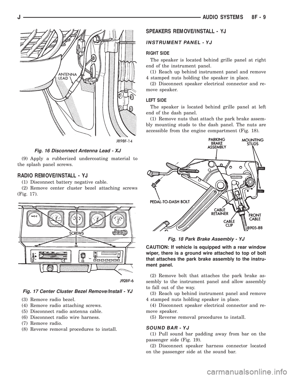
(2) Remove center cluster bezel attaching screws
(Fig. 17).
(3) Remove radio bezel.
(4) Remove radio attaching screws.
(5) Disconnect radio antenna cable.
(6) Disconnect radio wire harness.
(7) Remove radio.
(8) Reverse removal procedures to install.
SPEAKERS REMOVE/INSTALL - YJ
INSTRUMENT PANEL - YJ
RIGHT SIDE
The speaker is located behind grille panel at right
end of the instrument panel.
(1) Reach up behind instrument panel and remove
4 stamped nuts holding the speaker in place.
(2) Disconnect speaker electrical connector and re-
move speaker.
LEFT SIDE
The speaker is located behind grille panel at left
end of the dash panel.
(1) Remove nuts that attach the park brake assem-
bly mounting studs to the dash panel. The nuts are
accessible from the engine compartment (Fig. 18).
CAUTION: If vehicle is equipped with a rear window
wiper, there is a ground wire attached to top of bolt
that attaches the park brake assembly to the instru-
ment panel.
(2) Remove bolt that attaches the park brake as-
sembly to the instrument panel and allow assembly
to fall out of the way.
(3) Reach up behind instrument panel and remove
4 stamped nuts holding speaker in place.
(4) Disconnect speaker electrical connector and re-
move speaker.
(5) Reverse removal procedures to install.
SOUND BAR - YJ
(1) Pull sound bar padding away from bar on the
passenger side (Fig. 19).
(2) Disconnect speaker harness connector located
on the passenger side at the sound bar.
Fig. 16 Disconnect Antenna Lead - XJ
Fig. 17 Center Cluster Bezel Remove/Install - YJ
Fig. 18 Park Brake Assembly - YJ
JAUDIO SYSTEMS 8F - 9
Page 400 of 2198
SERVICE PROCEDURES
HORN REMOVE/INSTALL
XJ
(1) Raise and support the vehicle.
(2) Remove the front underbody splash shield.
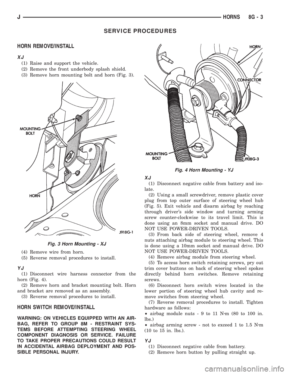
(3) Remove horn mounting bolt and horn (Fig. 3).
(4) Remove wire from horn.
(5) Reverse removal procedures to install.
YJ
(1) Disconnect wire harness connector from the
horn (Fig. 4).
(2) Remove horn and bracket mounting bolt. Horn
and bracket are removed as an assembly.
(3) Reverse removal procedures to install.
HORN SWITCH REMOVE/INSTALL
WARNING: ON VEHICLES EQUIPPED WITH AN AIR-
BAG, REFER TO GROUP 8M - RESTRAINT SYS-
TEMS BEFORE ATTEMPTING STEERING WHEEL
COMPONENT DIAGNOSIS OR SERVICE. FAILURE
TO TAKE PROPER PRECAUTIONS COULD RESULT
IN ACCIDENTAL AIRBAG DEPLOYMENT AND POS-
SIBLE PERSONAL INJURY.
XJ
(1) Disconnect negative cable from battery and iso-
late.
(2) Using a small screwdriver, remove plastic cover
plug from top outer surface of steering wheel hub
(Fig. 5). Exit vehicle and disarm airbag by reaching
through driver's side window and turning arming
screw counter-clockwise to its travel limit. This is
done using an 8mm socket and manual drive. DO
NOT USE POWER-DRIVEN TOOLS.
(3) From back side of steering wheel, remove 4
nuts attaching airbag module to steering wheel. This
is done using a 10mm socket and manual drive. DO
NOT USE POWER-DRIVEN TOOLS.
(4) Remove airbag module from steering wheel.
(5) To access horn switch retaining screws, pry out
trim cover buttons on back of steering wheel spokes
directly behind horn switches. Remove retaining
screws.
(6) Disconnect horn switch wires located in the
lower portion of steering wheel hub cavity and re-
move switches from steering wheel.
(7) Reverse removal procedures to install. Tighten
hardware as follows:
²airbag module nuts-9to11Nzm (80 to 100 in.
lbs.)
²airbag arming screw - not to exceed 1 to 1.5 Nzm
(10 to 15 in. lbs.).
YJ
(1) Disconnect negative cable from battery.
(2) Remove horn button by pulling straight up.
Fig. 3 Horn Mounting - XJ
Fig. 4 Horn Mounting - YJ
JHORNS 8G - 3
Page 428 of 2198
(8) Remove the wiper motor mounting screws.
(9) Remove the wiper motor.
(10) Reverse removal procedures to install. Tighten
pivot pin retaining nut to 4 Nzm (32 in. lbs.). Lubri-
cate the bezel nipples with a small amount of water
when installing washer hoses. The liftgate wiper
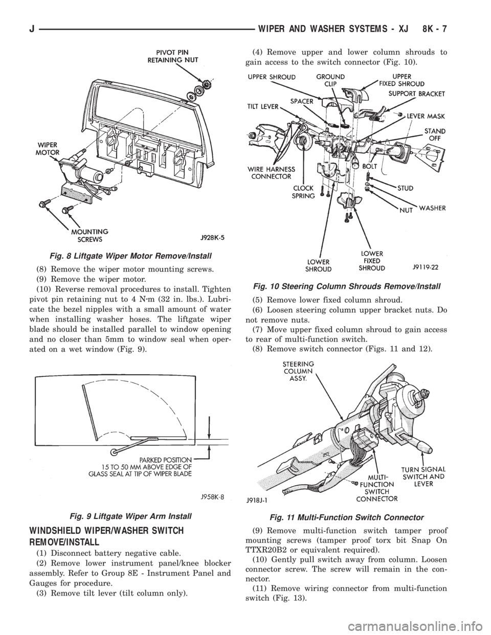
blade should be installed parallel to window opening
and no closer than 5mm to window seal when oper-
ated on a wet window (Fig. 9).
WINDSHIELD WIPER/WASHER SWITCH
REMOVE/INSTALL
(1) Disconnect battery negative cable.
(2) Remove lower instrument panel/knee blocker
assembly. Refer to Group 8E - Instrument Panel and
Gauges for procedure.
(3) Remove tilt lever (tilt column only).(4) Remove upper and lower column shrouds to
gain access to the switch connector (Fig. 10).
(5) Remove lower fixed column shroud.
(6) Loosen steering column upper bracket nuts. Do
not remove nuts.
(7) Move upper fixed column shroud to gain access
to rear of multi-function switch.
(8) Remove switch connector (Figs. 11 and 12).
(9) Remove multi-function switch tamper proof
mounting screws (tamper proof torx bit Snap On
TTXR20B2 or equivalent required).
(10) Gently pull switch away from column. Loosen
connector screw. The screw will remain in the con-
nector.
(11) Remove wiring connector from multi-function
switch (Fig. 13).
Fig. 8 Liftgate Wiper Motor Remove/Install
Fig. 9 Liftgate Wiper Arm Install
Fig. 10 Steering Column Shrouds Remove/Install
Fig. 11 Multi-Function Switch Connector
JWIPER AND WASHER SYSTEMS - XJ 8K - 7
Page 459 of 2198
BACK-UP/REAR TURN SIGNAL/TAIL LAMP BULB
REPLACEMENTÐXJ
REMOVAL
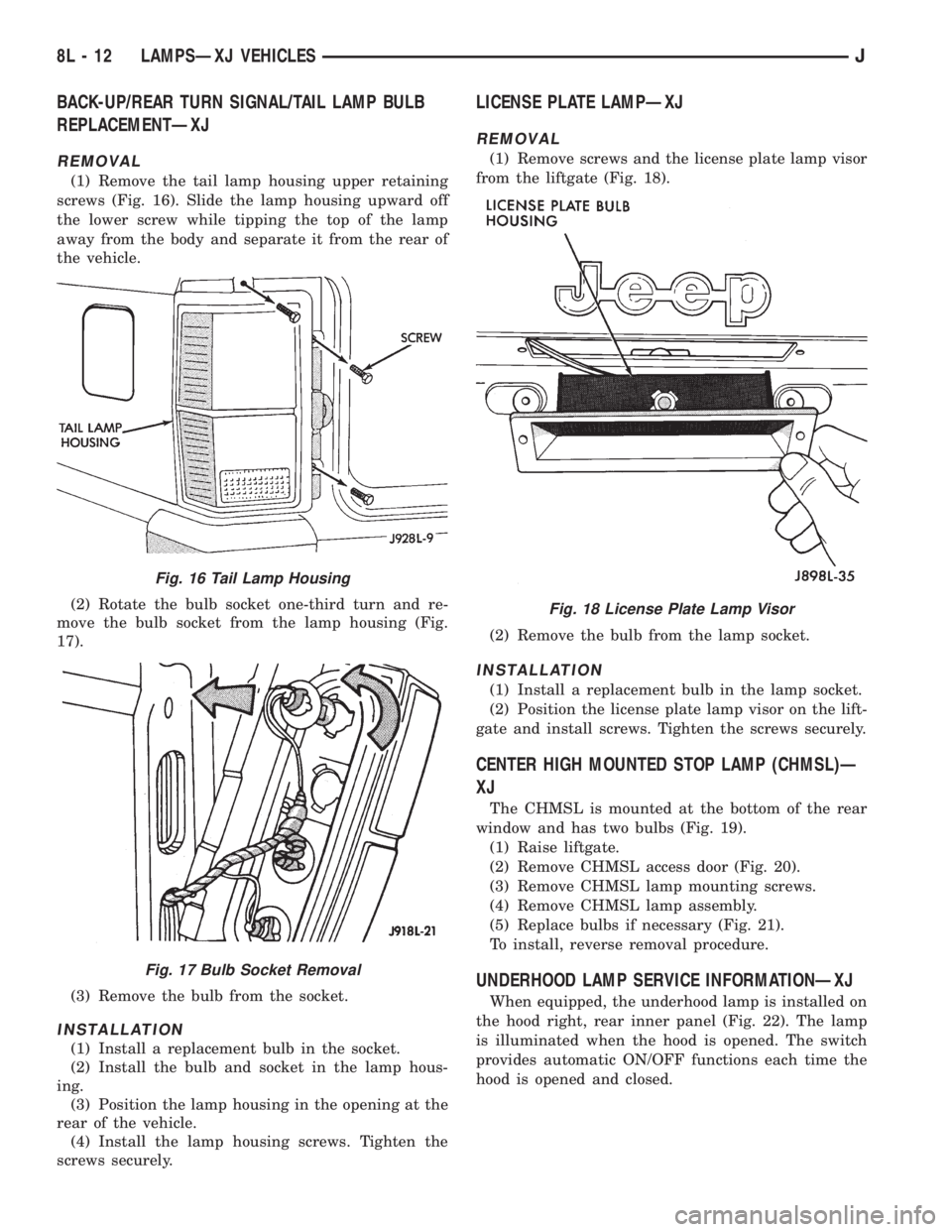
(1) Remove the tail lamp housing upper retaining
screws (Fig. 16). Slide the lamp housing upward off
the lower screw while tipping the top of the lamp
away from the body and separate it from the rear of
the vehicle.
(2) Rotate the bulb socket one-third turn and re-
move the bulb socket from the lamp housing (Fig.
17).
(3) Remove the bulb from the socket.
INSTALLATION
(1) Install a replacement bulb in the socket.
(2) Install the bulb and socket in the lamp hous-
ing.
(3) Position the lamp housing in the opening at the
rear of the vehicle.
(4) Install the lamp housing screws. Tighten the
screws securely.
LICENSE PLATE LAMPÐXJ
REMOVAL
(1) Remove screws and the license plate lamp visor
from the liftgate (Fig. 18).
(2) Remove the bulb from the lamp socket.
INSTALLATION
(1) Install a replacement bulb in the lamp socket.
(2) Position the license plate lamp visor on the lift-
gate and install screws. Tighten the screws securely.
CENTER HIGH MOUNTED STOP LAMP (CHMSL)Ð
XJ
The CHMSL is mounted at the bottom of the rear
window and has two bulbs (Fig. 19).
(1) Raise liftgate.
(2) Remove CHMSL access door (Fig. 20).
(3) Remove CHMSL lamp mounting screws.
(4) Remove CHMSL lamp assembly.
(5) Replace bulbs if necessary (Fig. 21).
To install, reverse removal procedure.
UNDERHOOD LAMP SERVICE INFORMATIONÐXJ
When equipped, the underhood lamp is installed on
the hood right, rear inner panel (Fig. 22). The lamp
is illuminated when the hood is opened. The switch
provides automatic ON/OFF functions each time the
hood is opened and closed.
Fig. 16 Tail Lamp Housing
Fig. 17 Bulb Socket Removal
Fig. 18 License Plate Lamp Visor
8L - 12 LAMPSÐXJ VEHICLESJ
Page 482 of 2198
DEPLOYED
Following an airbag deployment, the vehicle inte-
rior will contain a powdery residue. This residue is
primarily sodium bicarbonate (baking soda), used as
an airbag cushion lubricant. However, there will also
be traces of sodium hydroxide powder, a chemical
byproduct of the generant used for airbag deploy-
ment. Since this powder can irritate the skin, eyes,
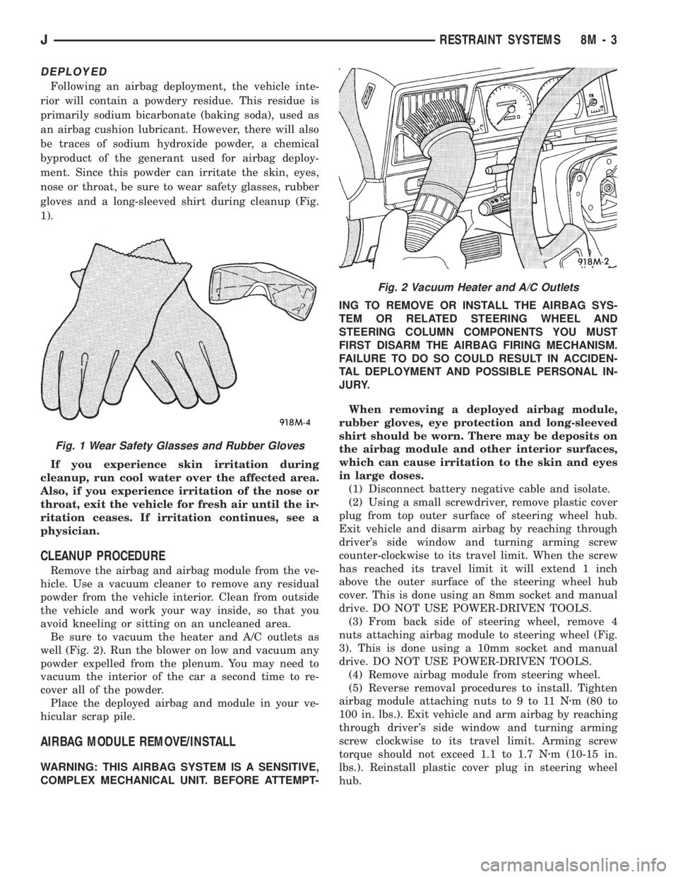
nose or throat, be sure to wear safety glasses, rubber
gloves and a long-sleeved shirt during cleanup (Fig.
1).
If you experience skin irritation during
cleanup, run cool water over the affected area.
Also, if you experience irritation of the nose or
throat, exit the vehicle for fresh air until the ir-
ritation ceases. If irritation continues, see a
physician.
CLEANUP PROCEDURE
Remove the airbag and airbag module from the ve-
hicle. Use a vacuum cleaner to remove any residual
powder from the vehicle interior. Clean from outside
the vehicle and work your way inside, so that you
avoid kneeling or sitting on an uncleaned area.
Be sure to vacuum the heater and A/C outlets as
well (Fig. 2). Run the blower on low and vacuum any
powder expelled from the plenum. You may need to
vacuum the interior of the car a second time to re-
cover all of the powder.
Place the deployed airbag and module in your ve-
hicular scrap pile.
AIRBAG MODULE REMOVE/INSTALL
WARNING: THIS AIRBAG SYSTEM IS A SENSITIVE,
COMPLEX MECHANICAL UNIT. BEFORE ATTEMPT-ING TO REMOVE OR INSTALL THE AIRBAG SYS-
TEM OR RELATED STEERING WHEEL AND
STEERING COLUMN COMPONENTS YOU MUST
FIRST DISARM THE AIRBAG FIRING MECHANISM.
FAILURE TO DO SO COULD RESULT IN ACCIDEN-
TAL DEPLOYMENT AND POSSIBLE PERSONAL IN-
JURY.
When removing a deployed airbag module,
rubber gloves, eye protection and long-sleeved
shirt should be worn. There may be deposits on
the airbag module and other interior surfaces,
which can cause irritation to the skin and eyes
in large doses.
(1) Disconnect battery negative cable and isolate.
(2) Using a small screwdriver, remove plastic cover
plug from top outer surface of steering wheel hub.
Exit vehicle and disarm airbag by reaching through
driver's side window and turning arming screw
counter-clockwise to its travel limit. When the screw
has reached its travel limit it will extend 1 inch
above the outer surface of the steering wheel hub
cover. This is done using an 8mm socket and manual
drive. DO NOT USE POWER-DRIVEN TOOLS.
(3) From back side of steering wheel, remove 4
nuts attaching airbag module to steering wheel (Fig.
3). This is done using a 10mm socket and manual
drive. DO NOT USE POWER-DRIVEN TOOLS.
(4) Remove airbag module from steering wheel.
(5) Reverse removal procedures to install. Tighten
airbag module attaching nuts to 9 to 11 Nzm (80 to
100 in. lbs.). Exit vehicle and arm airbag by reaching
through driver's side window and turning arming
screw clockwise to its travel limit. Arming screw
torque should not exceed 1.1 to 1.7 Nzm (10-15 in.
lbs.). Reinstall plastic cover plug in steering wheel
hub.
Fig. 1 Wear Safety Glasses and Rubber Gloves
Fig. 2 Vacuum Heater and A/C Outlets
JRESTRAINT SYSTEMS 8M - 3
Page 484 of 2198
REAR WINDOW DEFOGGER
CONTENTS
page page
DIAGNOSIS............................. 1
GENERAL INFORMATION.................. 1SERVICE PROCEDURES................... 3
GENERAL INFORMATION
The electrically-heated rear window defogger is an
available option on XJ (Cherokee), and YJ (Wrangler)
models equipped with the hardtop roof option. Fol-
lowing are general descriptions of the major compo-
nents in the rear window defogger system. Refer to
Group 8W - Wiring Diagrams for complete circuit de-
scriptions and diagrams.
REAR WINDOW GLASS GRID
The heated rear window glass has two electrically-
conductive vertical bus bars and a series of horizon-
tal grid lines made of a silver-ceramic material,
which is baked on and bonded to the inside surface of
the glass. The grid lines and bus bars comprise a
parallel electrical circuit.
When the rear window defogger switch is placed in
the ON position, current is directed to the rear win-
dow grid lines through the bus bars. The grid lines
heat the rear window to clear the surface of fog or
snow. Circuit protection for the heated grid circuit is
provided by fuse 18 (XJ) or fuse 6 (YJ) in the fuse-
block module.
The grid lines and bus bars are highly resistant to
abrasion. However, it is possible for an open to occur
in an individual grid line resulting in no current flow
through the line. The grid lines can be damaged or
scraped off with sharp instruments. Care should be
taken in cleaning the glass or removing foreign ma-
terials, decals or stickers. Normal glass cleaning sol-
vents or hot water used with rags or toweling is
recommended.A repair kit is available to repair the grid lines and
bus bars, or to reinstall the heated glass pigtail
wires.
DEFOGGER SWITCH
The rear window defogger switch is mounted in the
instrument panel left of the steering column for XJ,
or right of the steering column for YJ. The switch cir-
cuit is protected by fuse 8 (XJ) or fuse 9 (YJ) in the
fuseblock module. Actuating the switch energizes the
relay and electronic timer. A light-emitting diode
(LED) in the switch (XJ), or a indicator lamp in the
switch (YJ), illuminates to indicate when the system
is turned on. The defogger switch can not be re-
paired. If faulty, the switch must be replaced.
DEFOGGER RELAY/TIMER
The defogger relay/timer is located in the relay cen-
ter on XJ models, or taped to the instrument panel
wiring harness behind the parking brake pedal in the
left cowl side area on YJ models. When the rear de-
fogger switch is actuated, the rear defogger relay is
energized. This causes current to flow through the
grid circuit for approximately 10 minutes, or until
the rear window defogger switch or ignition switch
are turned off.
DIAGNOSIS
SYSTEM TESTS
Electrically-heated rear window defogger operation
can be confirmed in the following manner:
(1) Turn the ignition switch to the ON position.
(2) Turn rear window defogger control switch ON.
(3) Monitor vehicle voltmeter. With the control
switch ON, a distinct needle deflection should be
noted.(4) The rear window defogger operation can be
checked by feeling the glass. A distinct difference in
temperature between the grid lines and adjacent
clear glass can be detected within 3 to 4 minutes of
operation.
(5) Using a DC voltmeter, contact terminal A (Fig.
1) (passenger side) with the negative lead, and termi-
JREAR WINDOW DEFOGGER 8N - 1
Page 485 of 2198
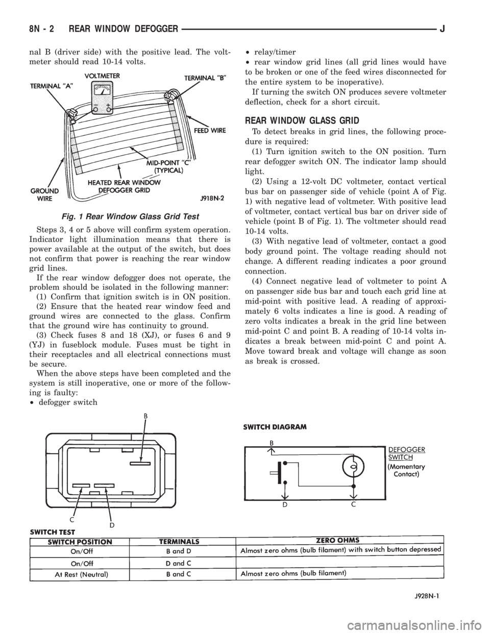
nal B (driver side) with the positive lead. The volt-
meter should read 10-14 volts.
Steps 3, 4 or 5 above will confirm system operation.
Indicator light illumination means that there is
power available at the output of the switch, but does
not confirm that power is reaching the rear window
grid lines.
If the rear window defogger does not operate, the
problem should be isolated in the following manner:
(1) Confirm that ignition switch is in ON position.
(2) Ensure that the heated rear window feed and
ground wires are connected to the glass. Confirm
that the ground wire has continuity to ground.
(3) Check fuses 8 and 18 (XJ), or fuses 6 and 9
(YJ) in fuseblock module. Fuses must be tight in
their receptacles and all electrical connections must
be secure.
When the above steps have been completed and the
system is still inoperative, one or more of the follow-
ing is faulty:
²defogger switch²relay/timer
²rear window grid lines (all grid lines would have
to be broken or one of the feed wires disconnected for
the entire system to be inoperative).
If turning the switch ON produces severe voltmeter
deflection, check for a short circuit.
REAR WINDOW GLASS GRID
To detect breaks in grid lines, the following proce-
dure is required:
(1) Turn ignition switch to the ON position. Turn
rear defogger switch ON. The indicator lamp should
light.
(2) Using a 12-volt DC voltmeter, contact vertical
bus bar on passenger side of vehicle (point A of Fig.
1) with negative lead of voltmeter. With positive lead
of voltmeter, contact vertical bus bar on driver side of
vehicle (point B of Fig. 1). The voltmeter should read
10-14 volts.
(3) With negative lead of voltmeter, contact a good
body ground point. The voltage reading should not
change. A different reading indicates a poor ground
connection.
(4) Connect negative lead of voltmeter to point A
on passenger side bus bar and touch each grid line at
mid-point with positive lead. A reading of approxi-
mately 6 volts indicates a line is good. A reading of
zero volts indicates a break in the grid line between
mid-point C and point B. A reading of 10-14 volts in-
dicates a break between mid-point C and point A.
Move toward break and voltage will change as soon
as break is crossed.
Fig. 1 Rear Window Glass Grid Test
8N - 2 REAR WINDOW DEFOGGERJ