1995 JEEP CHEROKEE torque
[x] Cancel search: torquePage 300 of 2198
(4) Remove nut from lower end of brace rod (auto-
matic transmission only).
(5) Remove brace rod and bracket (automatic
transmission only).
(6) Remove nut, bolt and bracket from bell housing
(manual transmission only).
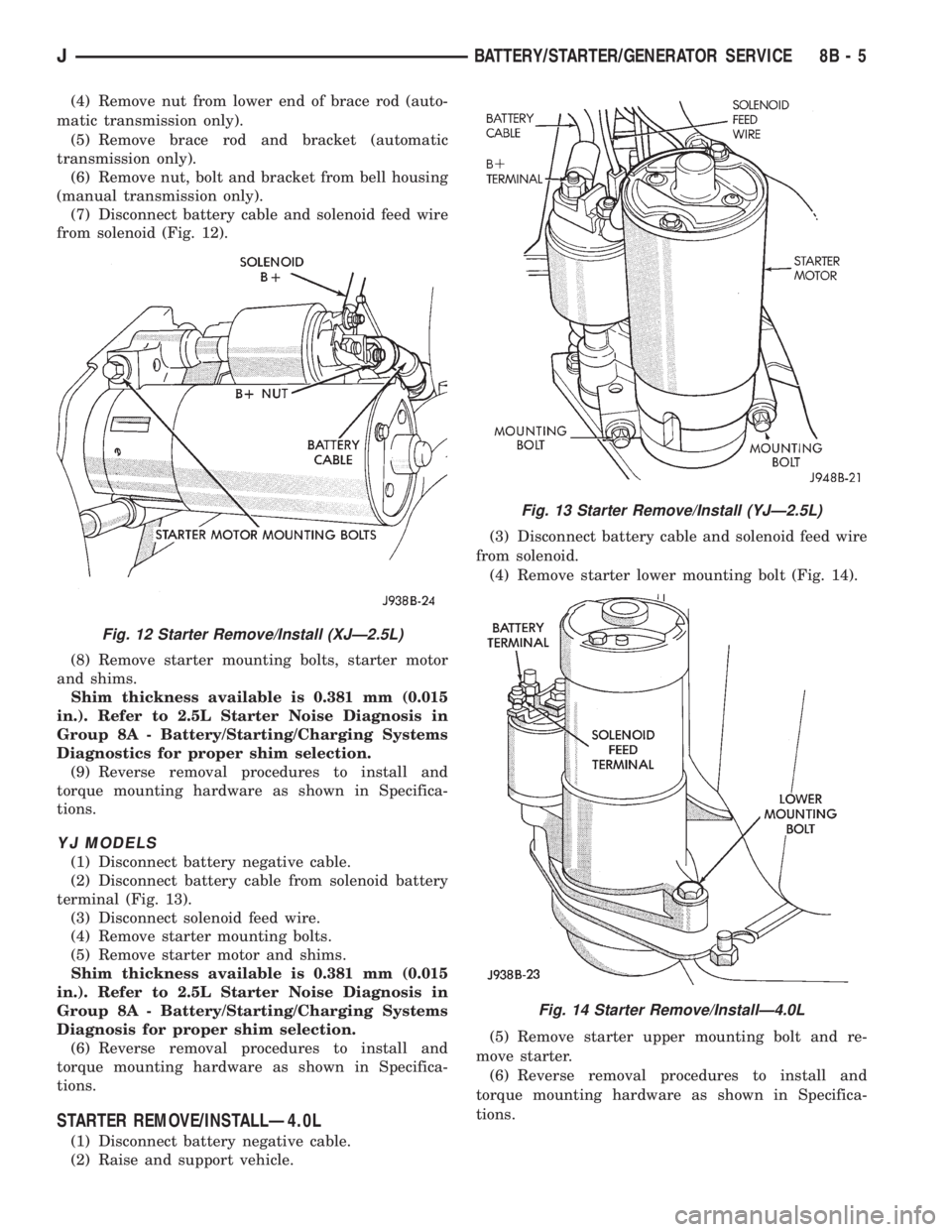
(7) Disconnect battery cable and solenoid feed wire
from solenoid (Fig. 12).
(8) Remove starter mounting bolts, starter motor
and shims.
Shim thickness available is 0.381 mm (0.015
in.). Refer to 2.5L Starter Noise Diagnosis in
Group 8A - Battery/Starting/Charging Systems
Diagnostics for proper shim selection.
(9) Reverse removal procedures to install and
torque mounting hardware as shown in Specifica-
tions.
YJ MODELS
(1) Disconnect battery negative cable.
(2) Disconnect battery cable from solenoid battery
terminal (Fig. 13).
(3) Disconnect solenoid feed wire.
(4) Remove starter mounting bolts.
(5) Remove starter motor and shims.
Shim thickness available is 0.381 mm (0.015
in.). Refer to 2.5L Starter Noise Diagnosis in
Group 8A - Battery/Starting/Charging Systems
Diagnosis for proper shim selection.
(6) Reverse removal procedures to install and
torque mounting hardware as shown in Specifica-
tions.
STARTER REMOVE/INSTALLÐ4.0L
(1) Disconnect battery negative cable.
(2) Raise and support vehicle.(3) Disconnect battery cable and solenoid feed wire
from solenoid.
(4) Remove starter lower mounting bolt (Fig. 14).
(5) Remove starter upper mounting bolt and re-
move starter.
(6) Reverse removal procedures to install and
torque mounting hardware as shown in Specifica-
tions.
Fig. 12 Starter Remove/Install (XJÐ2.5L)
Fig. 13 Starter Remove/Install (YJÐ2.5L)
Fig. 14 Starter Remove/InstallÐ4.0L
JBATTERY/STARTER/GENERATOR SERVICE 8B - 5
Page 301 of 2198
STARTER RELAY REMOVE/INSTALL
(1) Disconnect battery negative cable.
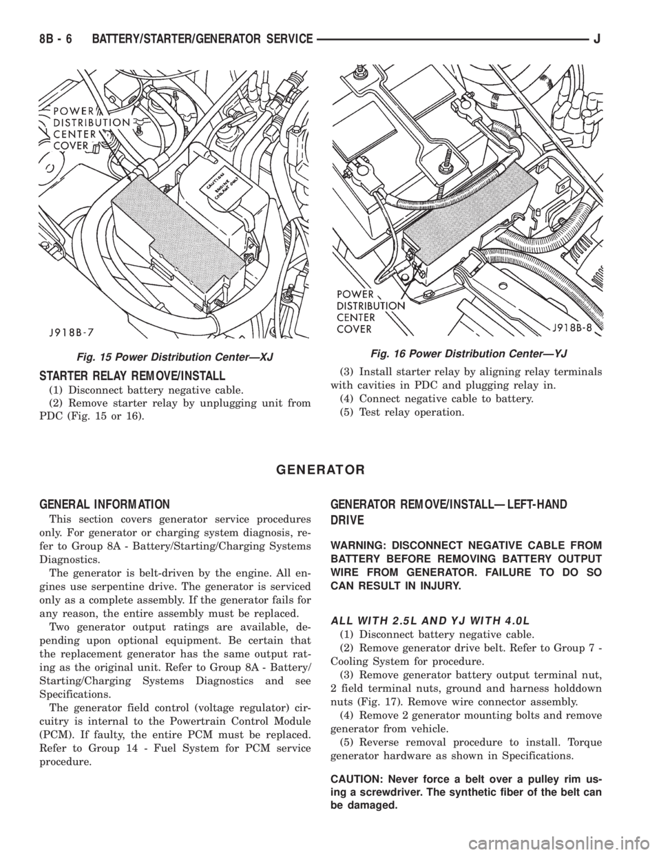
(2) Remove starter relay by unplugging unit from
PDC (Fig. 15 or 16).(3) Install starter relay by aligning relay terminals
with cavities in PDC and plugging relay in.
(4) Connect negative cable to battery.
(5) Test relay operation.
GENERATOR
GENERAL INFORMATION
This section covers generator service procedures
only. For generator or charging system diagnosis, re-
fer to Group 8A - Battery/Starting/Charging Systems
Diagnostics.
The generator is belt-driven by the engine. All en-
gines use serpentine drive. The generator is serviced
only as a complete assembly. If the generator fails for
any reason, the entire assembly must be replaced.
Two generator output ratings are available, de-
pending upon optional equipment. Be certain that
the replacement generator has the same output rat-
ing as the original unit. Refer to Group 8A - Battery/
Starting/Charging Systems Diagnostics and see
Specifications.
The generator field control (voltage regulator) cir-
cuitry is internal to the Powertrain Control Module
(PCM). If faulty, the entire PCM must be replaced.
Refer to Group 14 - Fuel System for PCM service
procedure.
GENERATOR REMOVE/INSTALLÐLEFT-HAND
DRIVE
WARNING: DISCONNECT NEGATIVE CABLE FROM
BATTERY BEFORE REMOVING BATTERY OUTPUT
WIRE FROM GENERATOR. FAILURE TO DO SO
CAN RESULT IN INJURY.
ALL WITH 2.5L AND YJ WITH 4.0L
(1) Disconnect battery negative cable.
(2) Remove generator drive belt. Refer to Group 7 -
Cooling System for procedure.
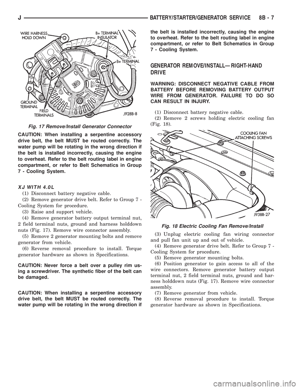
(3) Remove generator battery output terminal nut,
2 field terminal nuts, ground and harness holddown
nuts (Fig. 17). Remove wire connector assembly.
(4) Remove 2 generator mounting bolts and remove
generator from vehicle.
(5) Reverse removal procedure to install. Torque
generator hardware as shown in Specifications.
CAUTION: Never force a belt over a pulley rim us-
ing a screwdriver. The synthetic fiber of the belt can
be damaged.
Fig. 15 Power Distribution CenterÐXJFig. 16 Power Distribution CenterÐYJ
8B - 6 BATTERY/STARTER/GENERATOR SERVICEJ
Page 302 of 2198
CAUTION: When installing a serpentine accessory
drive belt, the belt MUST be routed correctly. The
water pump will be rotating in the wrong direction if
the belt is installed incorrectly, causing the engine
to overheat. Refer to the belt routing label in engine
compartment, or refer to Belt Schematics in Group
7 - Cooling System.
XJ WITH 4.0L
(1) Disconnect battery negative cable.
(2) Remove generator drive belt. Refer to Group 7 -
Cooling System for procedure.
(3) Raise and support vehicle.
(4) Remove generator battery output terminal nut,
2 field terminal nuts, ground and harness holddown
nuts (Fig. 17). Remove wire connector assembly.
(5) Remove 2 generator mounting bolts and remove
generator from vehicle.
(6) Reverse removal procedure to install. Torque
generator hardware as shown in Specifications.
CAUTION: Never force a belt over a pulley rim us-
ing a screwdriver. The synthetic fiber of the belt can
be damaged.
CAUTION: When installing a serpentine accessory
drive belt, the belt MUST be routed correctly. The
water pump will be rotating in the wrong direction ifthe belt is installed incorrectly, causing the engine
to overheat. Refer to the belt routing label in engine
compartment, or refer to Belt Schematics in Group
7 - Cooling System.
GENERATOR REMOVE/INSTALLÐRIGHT-HAND
DRIVE
WARNING: DISCONNECT NEGATIVE CABLE FROM
BATTERY BEFORE REMOVING BATTERY OUTPUT
WIRE FROM GENERATOR. FAILURE TO DO SO
CAN RESULT IN INJURY.
(1) Disconnect battery negative cable.
(2) Remove 2 screws holding electric cooling fan
(Fig. 18).
(3) Unplug electric cooling fan wiring connector
and pull fan unit up and out of vehicle.
(4) Remove generator drive belt. Refer to Group 7 -
Cooling System for procedure.
(5) Remove generator mounting bolts.
(6) Position generator to gain access to all of the
wire connectors. Remove generator battery output
terminal nut, 2 field terminal nuts, ground and har-
ness holddown nuts (Fig. 17). Remove wire connector
assembly.
(7) Remove generator from vehicle.
(8) Reverse removal procedure to install. Torque
generator hardware as shown in Specifications.
Fig. 17 Remove/Install Generator Connector
Fig. 18 Electric Cooling Fan Remove/Install
JBATTERY/STARTER/GENERATOR SERVICE 8B - 7
Page 303 of 2198
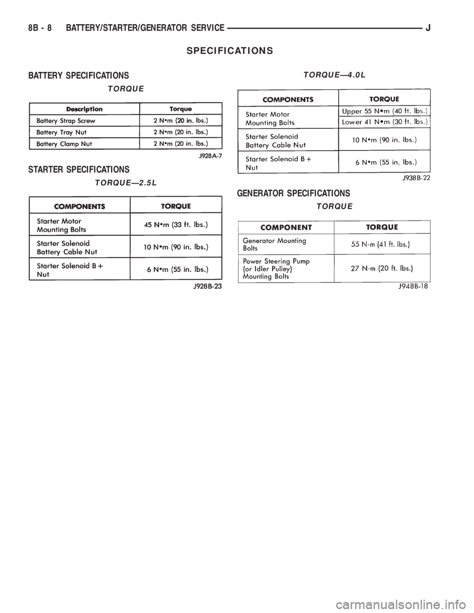
SPECIFICATIONS
BATTERY SPECIFICATIONS
STARTER SPECIFICATIONS
GENERATOR SPECIFICATIONS
TORQUE
TORQUEÐ2.5L
TORQUEÐ4.0L
TORQUE
8B - 8 BATTERY/STARTER/GENERATOR SERVICEJ
Page 310 of 2198
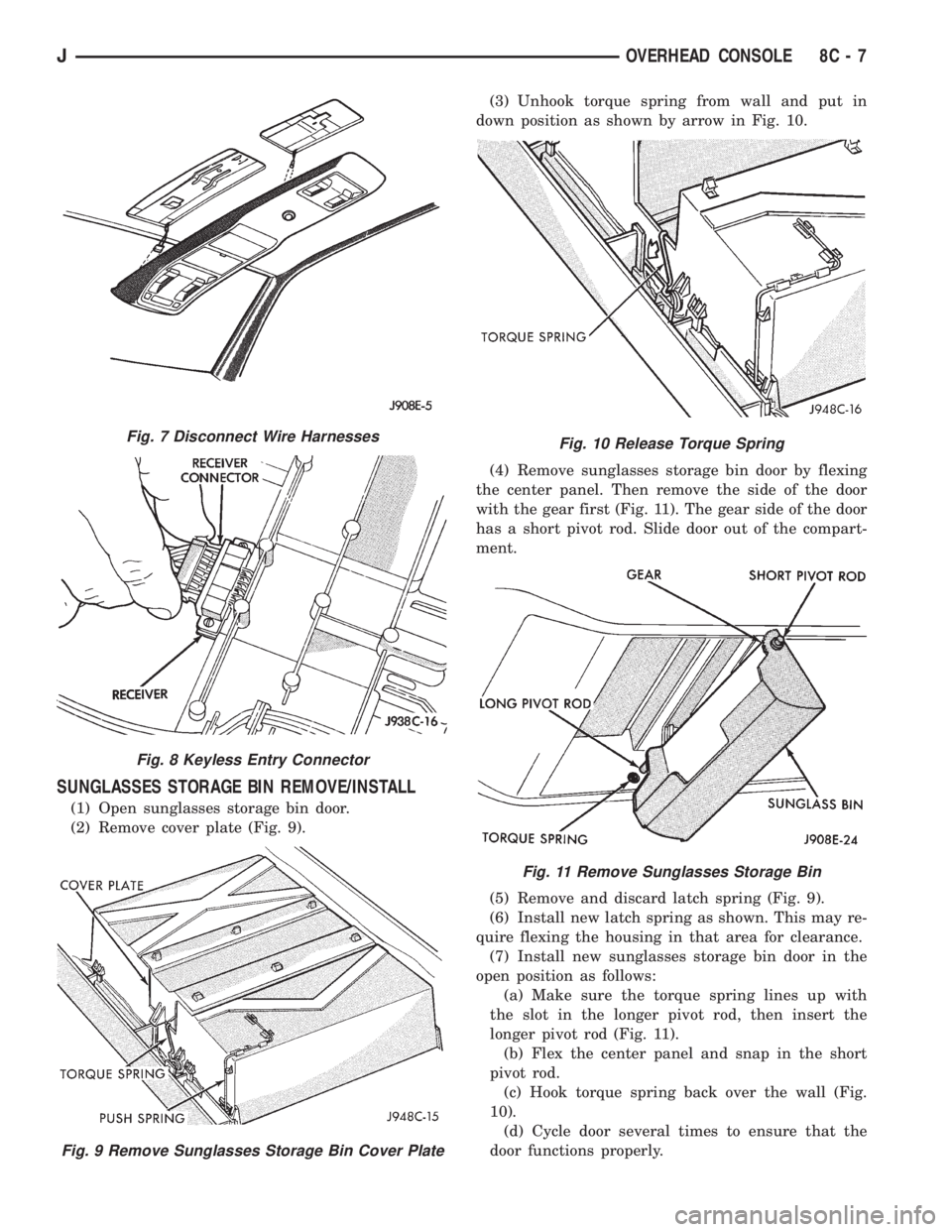
SUNGLASSES STORAGE BIN REMOVE/INSTALL
(1) Open sunglasses storage bin door.
(2) Remove cover plate (Fig. 9).(3) Unhook torque spring from wall and put in
down position as shown by arrow in Fig. 10.
(4) Remove sunglasses storage bin door by flexing
the center panel. Then remove the side of the door
with the gear first (Fig. 11). The gear side of the door
has a short pivot rod. Slide door out of the compart-
ment.
(5) Remove and discard latch spring (Fig. 9).
(6) Install new latch spring as shown. This may re-
quire flexing the housing in that area for clearance.
(7) Install new sunglasses storage bin door in the
open position as follows:
(a) Make sure the torque spring lines up with
the slot in the longer pivot rod, then insert the
longer pivot rod (Fig. 11).
(b) Flex the center panel and snap in the short
pivot rod.
(c) Hook torque spring back over the wall (Fig.
10).
(d) Cycle door several times to ensure that the
door functions properly.
Fig. 7 Disconnect Wire Harnesses
Fig. 8 Keyless Entry Connector
Fig. 9 Remove Sunglasses Storage Bin Cover Plate
Fig. 10 Release Torque Spring
Fig. 11 Remove Sunglasses Storage Bin
JOVERHEAD CONSOLE 8C - 7
Page 324 of 2198
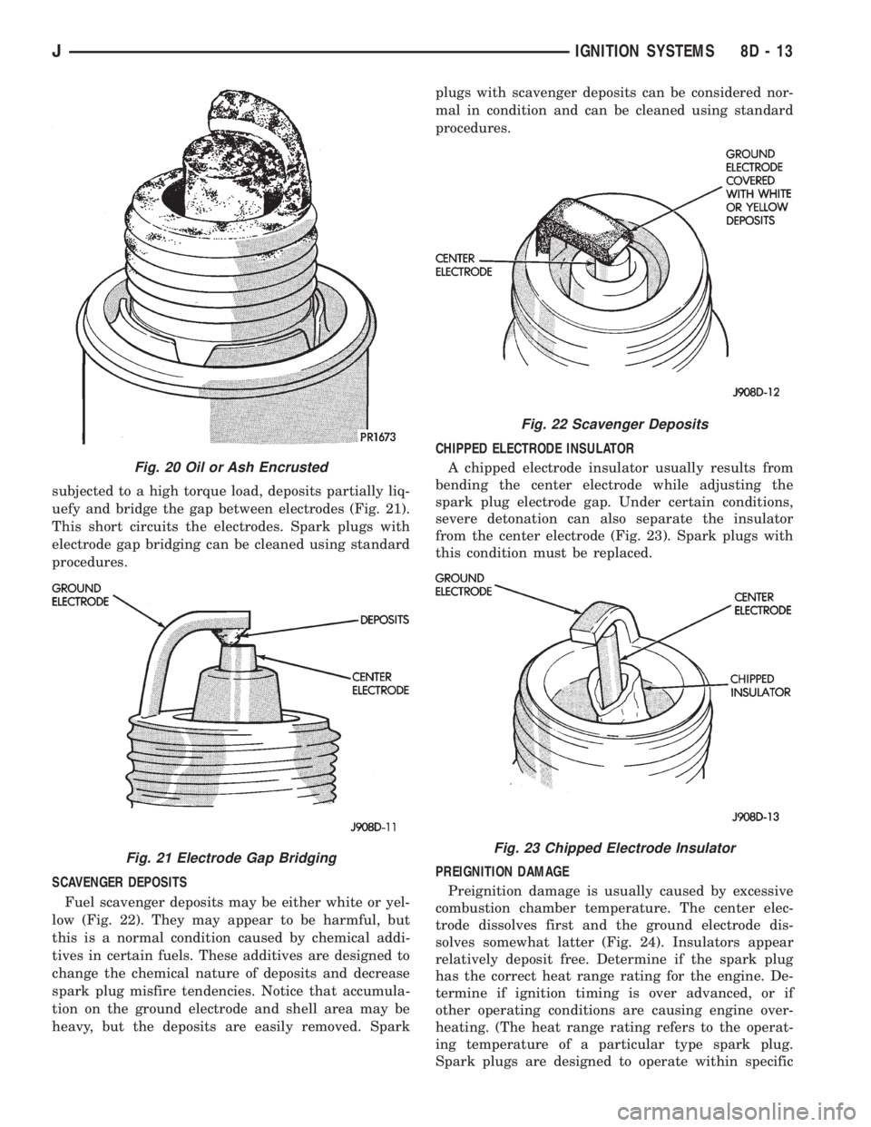
subjected to a high torque load, deposits partially liq-
uefy and bridge the gap between electrodes (Fig. 21).
This short circuits the electrodes. Spark plugs with
electrode gap bridging can be cleaned using standard
procedures.
SCAVENGER DEPOSITS
Fuel scavenger deposits may be either white or yel-
low (Fig. 22). They may appear to be harmful, but
this is a normal condition caused by chemical addi-
tives in certain fuels. These additives are designed to
change the chemical nature of deposits and decrease
spark plug misfire tendencies. Notice that accumula-
tion on the ground electrode and shell area may be
heavy, but the deposits are easily removed. Sparkplugs with scavenger deposits can be considered nor-
mal in condition and can be cleaned using standard
procedures.
CHIPPED ELECTRODE INSULATOR
A chipped electrode insulator usually results from
bending the center electrode while adjusting the
spark plug electrode gap. Under certain conditions,
severe detonation can also separate the insulator
from the center electrode (Fig. 23). Spark plugs with
this condition must be replaced.
PREIGNITION DAMAGE
Preignition damage is usually caused by excessive
combustion chamber temperature. The center elec-
trode dissolves first and the ground electrode dis-
solves somewhat latter (Fig. 24). Insulators appear
relatively deposit free. Determine if the spark plug
has the correct heat range rating for the engine. De-
termine if ignition timing is over advanced, or if
other operating conditions are causing engine over-
heating. (The heat range rating refers to the operat-
ing temperature of a particular type spark plug.
Spark plugs are designed to operate within specific
Fig. 20 Oil or Ash Encrusted
Fig. 21 Electrode Gap Bridging
Fig. 22 Scavenger Deposits
Fig. 23 Chipped Electrode Insulator
JIGNITION SYSTEMS 8D - 13
Page 329 of 2198
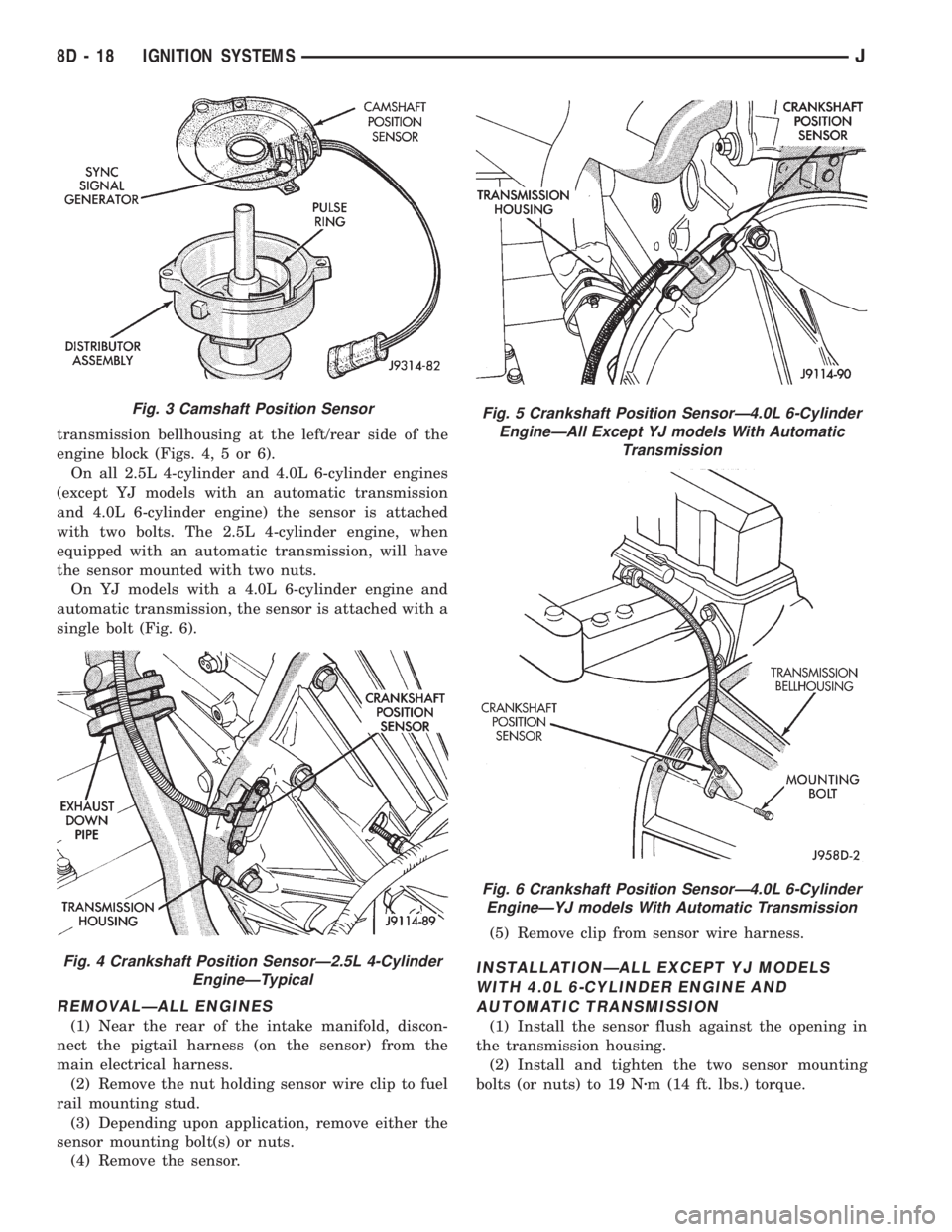
transmission bellhousing at the left/rear side of the
engine block (Figs. 4, 5 or 6).
On all 2.5L 4-cylinder and 4.0L 6-cylinder engines
(except YJ models with an automatic transmission
and 4.0L 6-cylinder engine) the sensor is attached
with two bolts. The 2.5L 4-cylinder engine, when
equipped with an automatic transmission, will have
the sensor mounted with two nuts.
On YJ models with a 4.0L 6-cylinder engine and
automatic transmission, the sensor is attached with a
single bolt (Fig. 6).
REMOVALÐALL ENGINES
(1) Near the rear of the intake manifold, discon-
nect the pigtail harness (on the sensor) from the
main electrical harness.
(2) Remove the nut holding sensor wire clip to fuel
rail mounting stud.
(3) Depending upon application, remove either the
sensor mounting bolt(s) or nuts.
(4) Remove the sensor.(5) Remove clip from sensor wire harness.
INSTALLATIONÐALL EXCEPT YJ MODELS
WITH 4.0L 6-CYLINDER ENGINE AND
AUTOMATIC TRANSMISSION
(1) Install the sensor flush against the opening in
the transmission housing.
(2) Install and tighten the two sensor mounting
bolts (or nuts) to 19 Nzm (14 ft. lbs.) torque.
Fig. 3 Camshaft Position Sensor
Fig. 4 Crankshaft Position SensorÐ2.5L 4-Cylinder
EngineÐTypical
Fig. 5 Crankshaft Position SensorÐ4.0L 6-Cylinder
EngineÐAll Except YJ models With Automatic
Transmission
Fig. 6 Crankshaft Position SensorÐ4.0L 6-Cylinder
EngineÐYJ models With Automatic Transmission
8D - 18 IGNITION SYSTEMSJ
Page 330 of 2198
CAUTION: On some models, two bolts are used to
secure the sensor to the transmission. These bolts
are specially machined to correctly space the unit
to the flywheel. Do not attempt to install any other
bolts.
(3) Connect the electrical connector to the sensor.
(4) Install clip on sensor wire harness.
(5) Install clip over fuel rail mounting stud. Install
clip mounting nut.
INSTALLATIONÐYJ MODELS WITH 4.0L
6-CYLINDER ENGINE AND AUTOMATIC
TRANSMISSION
(1) Install the sensor into the access hole on the
transmission.
(2) Install sensor mounting bolt (Fig. 6).
(3) Tighten sensor mounting bolt to 6-to-8 Nzm (50-
to-70 in. lbs.) torque.
(4) Connect the electrical connector to sensor.
(5) Install the clip to sensor wire harness.
(6) Install clip over fuel rail mounting stud. Install
clip mounting nut.
ENGINE COOLANT TEMPERATURE SENSOR
For an operational description, diagnosis and re-
moval/installation procedures, refer to Group 14,
Fuel System.
DISTRIBUTOR
GENERAL INFORMATION
All distributors contain an internal oil seal that
prevents oil from entering the distributor housing.
The seal is not serviceable.
Factory replacement distributors are equipped with
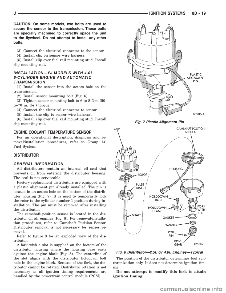
a plastic alignment pin already installed. The pin is
located in an access hole on the bottom of the distrib-
utor housing (Fig. 7). It is used to temporarily lock
the rotor to the cylinder number 1 position during in-
stallation. The pin must be removed after installing
the distributor.
The camshaft position sensor is located in the dis-
tributor on all engines (Fig. 8). For removal/installa-
tion procedures, refer to Camshaft Position Sensor.
Distributor removal is not necessary for sensor re-
moval.
Refer to figure 8 for an exploded view of the dis-
tributor.
A fork with a slot is supplied on the bottom of the
distributor housing where the housing base seats
against the engine block (Fig. 8). The centerline of
the slot aligns with the distributor holddown bolt
hole in the engine block. Because of the fork, the dis-
tributor cannot be rotated. Distributor rotation is not
necessary as all ignition timing requirements are
handled by the powertrain control module (PCM).The position of the distributor determines fuel syn-
chronization only. It does not determine ignition tim-
ing.
Do not attempt to modify this fork to attain
ignition timing.
Fig. 7 Plastic Alignment Pin
Fig. 8 DistributorÐ2.5L Or 4.0L EnginesÐTypical
JIGNITION SYSTEMS 8D - 19