1995 JEEP CHEROKEE torque
[x] Cancel search: torquePage 333 of 2198
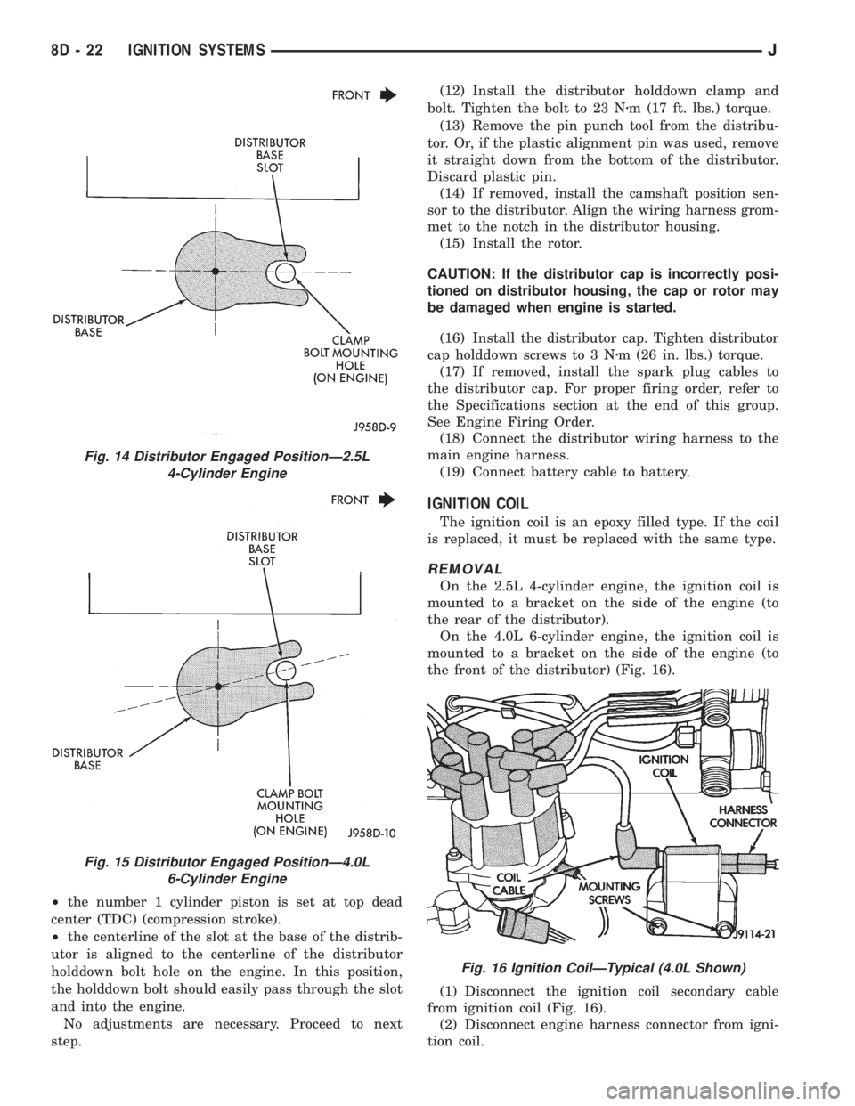
²the number 1 cylinder piston is set at top dead
center (TDC) (compression stroke).
²the centerline of the slot at the base of the distrib-
utor is aligned to the centerline of the distributor
holddown bolt hole on the engine. In this position,
the holddown bolt should easily pass through the slot
and into the engine.
No adjustments are necessary. Proceed to next
step.(12) Install the distributor holddown clamp and
bolt. Tighten the bolt to 23 Nzm (17 ft. lbs.) torque.
(13) Remove the pin punch tool from the distribu-
tor. Or, if the plastic alignment pin was used, remove
it straight down from the bottom of the distributor.
Discard plastic pin.
(14) If removed, install the camshaft position sen-
sor to the distributor. Align the wiring harness grom-
met to the notch in the distributor housing.
(15) Install the rotor.
CAUTION: If the distributor cap is incorrectly posi-
tioned on distributor housing, the cap or rotor may
be damaged when engine is started.
(16) Install the distributor cap. Tighten distributor
cap holddown screws to 3 Nzm (26 in. lbs.) torque.
(17) If removed, install the spark plug cables to
the distributor cap. For proper firing order, refer to
the Specifications section at the end of this group.
See Engine Firing Order.
(18) Connect the distributor wiring harness to the
main engine harness.
(19) Connect battery cable to battery.
IGNITION COIL
The ignition coil is an epoxy filled type. If the coil
is replaced, it must be replaced with the same type.
REMOVAL
On the 2.5L 4-cylinder engine, the ignition coil is
mounted to a bracket on the side of the engine (to
the rear of the distributor).
On the 4.0L 6-cylinder engine, the ignition coil is
mounted to a bracket on the side of the engine (to
the front of the distributor) (Fig. 16).
(1) Disconnect the ignition coil secondary cable
from ignition coil (Fig. 16).
(2) Disconnect engine harness connector from igni-
tion coil.
Fig. 14 Distributor Engaged PositionÐ2.5L
4-Cylinder Engine
Fig. 15 Distributor Engaged PositionÐ4.0L
6-Cylinder Engine
Fig. 16 Ignition CoilÐTypical (4.0L Shown)
8D - 22 IGNITION SYSTEMSJ
Page 334 of 2198
(3) Remove ignition coil mounting bolts (nuts are
used on back side of bracket). Remove coil.
INSTALLATION
(1) Install ignition coil to bracket on cylinder block
with mounting bolts and nuts.
(2) Connect engine harness connector to coil.
(3) Connect ignition coil cable to ignition coil.
INTAKE MANIFOLD AIR TEMPERATURE SENSOR
For an operational description, diagnosis or remov-
al/ installation procedures, refer to Group 14, Fuel
Systems.
MANIFOLD ABSOLUTE PRESSURE (MAP) SENSOR
For an operational description, diagnosis and re-
moval/installation procedures, refer to Group 14,
Fuel System.
OXYGEN (O2S) SENSOR
For an operational description, diagnosis or remov-
al/ installation procedures, refer to Group 14, Fuel
Systems.
POWERTRAIN CONTROL MODULE (PCM)
The PCM was formerly referred to as the SBEC or
engine controller.
XJ MODELS
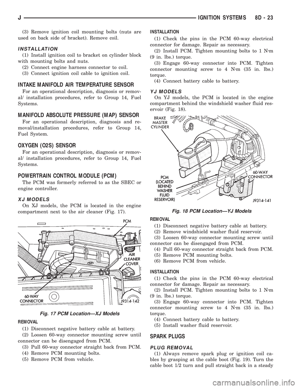
On XJ models, the PCM is located in the engine
compartment next to the air cleaner (Fig. 17).
REMOVAL
(1) Disconnect negative battery cable at battery.
(2) Loosen 60-way connector mounting screw until
connector can be disengaged from PCM.
(3) Pull 60-way connector straight back from PCM.
(4) Remove PCM mounting bolts.
(5) Remove PCM from vehicle.INSTALLATION
(1) Check the pins in the PCM 60-way electrical
connector for damage. Repair as necessary.
(2) Install PCM. Tighten mounting bolts to 1 Nzm
(9 in. lbs.) torque.
(3) Engage 60-way connector into PCM. Tighten
connector mounting screw to 4 Nzm (35 in. lbs.)
torque.
(4) Connect battery cable to battery.
YJ MODELS
On YJ models, the PCM is located in the engine
compartment behind the windshield washer fluid res-
ervoir (Fig. 18).
REMOVAL
(1) Disconnect negative battery cable at battery.
(2) Remove windshield washer fluid reservoir.
(3) Loosen 60-way connector mounting screw until
connector can be disengaged from PCM.
(4) Pull 60-way connector straight back from PCM.
(5) Remove PCM mounting bolts.
(6) Remove PCM from vehicle.
INSTALLATION
(1) Check the pins in the PCM 60-way electrical
connector for damage. Repair as necessary.
(2) Install PCM. Tighten mounting bolts to 1 Nzm
(9 in. lbs.) torque.
(3) Engage 60-way connector into PCM. Tighten
connector mounting screw to 4 Nzm (35 in. lbs.)
torque.
(4) Connect battery cable to battery.
(5) Install washer fluid reservoir.
SPARK PLUGS
PLUG REMOVAL
(1) Always remove spark plug or ignition coil ca-
bles by grasping at the cable boot (Fig. 19). Turn the
cable boot 1/2 turn and pull straight back in a steady
Fig. 17 PCM LocationÐXJ Models
Fig. 18 PCM LocationÐYJ Models
JIGNITION SYSTEMS 8D - 23
Page 335 of 2198
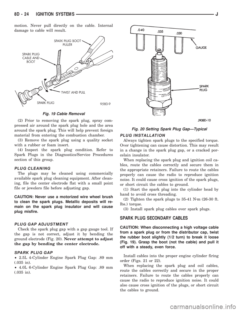
motion. Never pull directly on the cable. Internal
damage to cable will result.
(2) Prior to removing the spark plug, spray com-
pressed air around the spark plug hole and the area
around the spark plug. This will help prevent foreign
material from entering the combustion chamber.
(3) Remove the spark plug using a quality socket
with a rubber or foam insert.
(4) Inspect the spark plug condition. Refer to
Spark Plugs in the Diagnostics/Service Procedures
section of this group.
PLUG CLEANING
The plugs may be cleaned using commercially
available spark plug cleaning equipment. After clean-
ing, file the center electrode flat with a small point
file or jewelers file before adjusting gap.
CAUTION: Never use a motorized wire wheel brush
to clean the spark plugs. Metallic deposits will re-
main on the spark plug insulator and will cause
plug misfire.
PLUG GAP ADJUSTMENT
Check the spark plug gap with a gap gauge tool. If
the gap is not correct, adjust it by bending the
ground electrode (Fig. 20).Never attempt to adjust
the gap by bending the center electrode.
SPARK PLUG GAP
²2.5L 4-Cylinder Engine Spark Plug Gap: .89 mm
(.035 in).
²4.0L 6-Cylinder Engine Spark Plug Gap: .89 mm
(.035 in).
PLUG INSTALLATION
Always tighten spark plugs to the specified torque.
Over tightening can cause distortion. This may result
in a change in the spark plug gap, or a cracked por-
celain insulator.
When replacing the spark plug and ignition coil ca-
bles, route the cables correctly and secure them in
the appropriate retainers. Failure to route the cables
properly can cause the radio to reproduce ignition
noise. It could cause cross ignition of the spark plugs,
or short circuit the cables to ground.
(1) Start the spark plug into the cylinder head by
hand to avoid cross threading.
(2) Tighten the spark plugs to 35-41 Nzm (26-30 ft.
lbs.) torque.
(3) Install spark plug cables over spark plugs.
SPARK PLUG SECONDARY CABLES
CAUTION: When disconnecting a high voltage cable
from a spark plug or from the distributor cap, twist
the rubber boot slightly (1/2 turn) to break it loose
(Fig. 19). Grasp the boot (not the cable) and pull it
off with a steady, even force.
Install cables into the proper engine cylinder firing
order (Figs. 21 or 22).
When replacing the spark plug and coil cables,
route the cables correctly and secure in the proper
retainers. Failure to route the cables properly can
cause the radio to reproduce ignition noise. It could
also cause cross ignition of the plugs, or short circuit
the cables to ground.
Fig. 19 Cable Removal
Fig. 20 Setting Spark Plug GapÐTypical
8D - 24 IGNITION SYSTEMSJ
Page 338 of 2198
INSTALLATION
(1) Connect electrical connectors to ignition switch.
Make sure that switch locking tabs are fully seated
in wiring connectors.
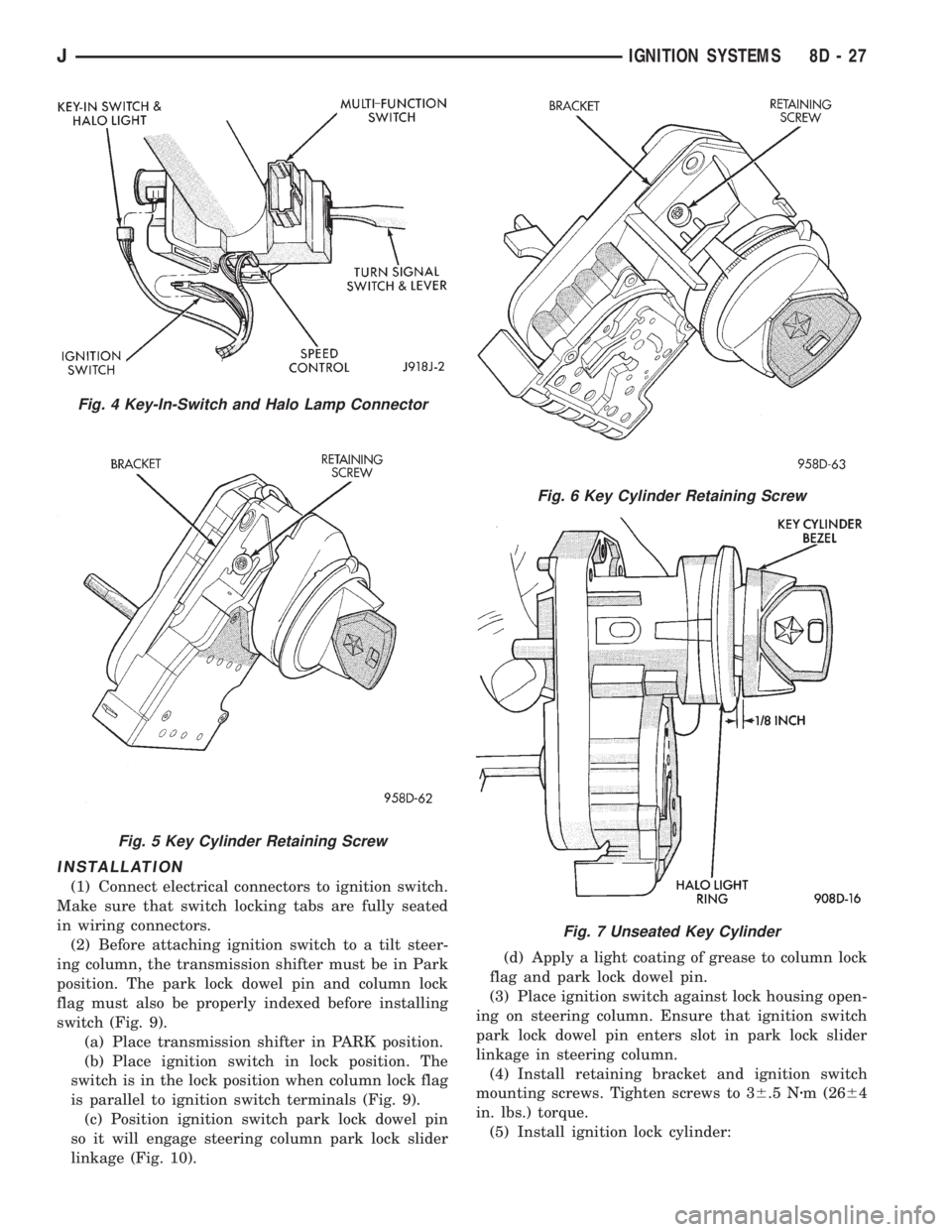
(2) Before attaching ignition switch to a tilt steer-
ing column, the transmission shifter must be in Park
position. The park lock dowel pin and column lock
flag must also be properly indexed before installing
switch (Fig. 9).
(a) Place transmission shifter in PARK position.
(b) Place ignition switch in lock position. The
switch is in the lock position when column lock flag
is parallel to ignition switch terminals (Fig. 9).
(c) Position ignition switch park lock dowel pin
so it will engage steering column park lock slider
linkage (Fig. 10).(d) Apply a light coating of grease to column lock
flag and park lock dowel pin.
(3) Place ignition switch against lock housing open-
ing on steering column. Ensure that ignition switch
park lock dowel pin enters slot in park lock slider
linkage in steering column.
(4) Install retaining bracket and ignition switch
mounting screws. Tighten screws to 36.5 Nzm (2664
in. lbs.) torque.
(5) Install ignition lock cylinder:
Fig. 4 Key-In-Switch and Halo Lamp Connector
Fig. 5 Key Cylinder Retaining Screw
Fig. 6 Key Cylinder Retaining Screw
Fig. 7 Unseated Key Cylinder
JIGNITION SYSTEMS 8D - 27
Page 339 of 2198
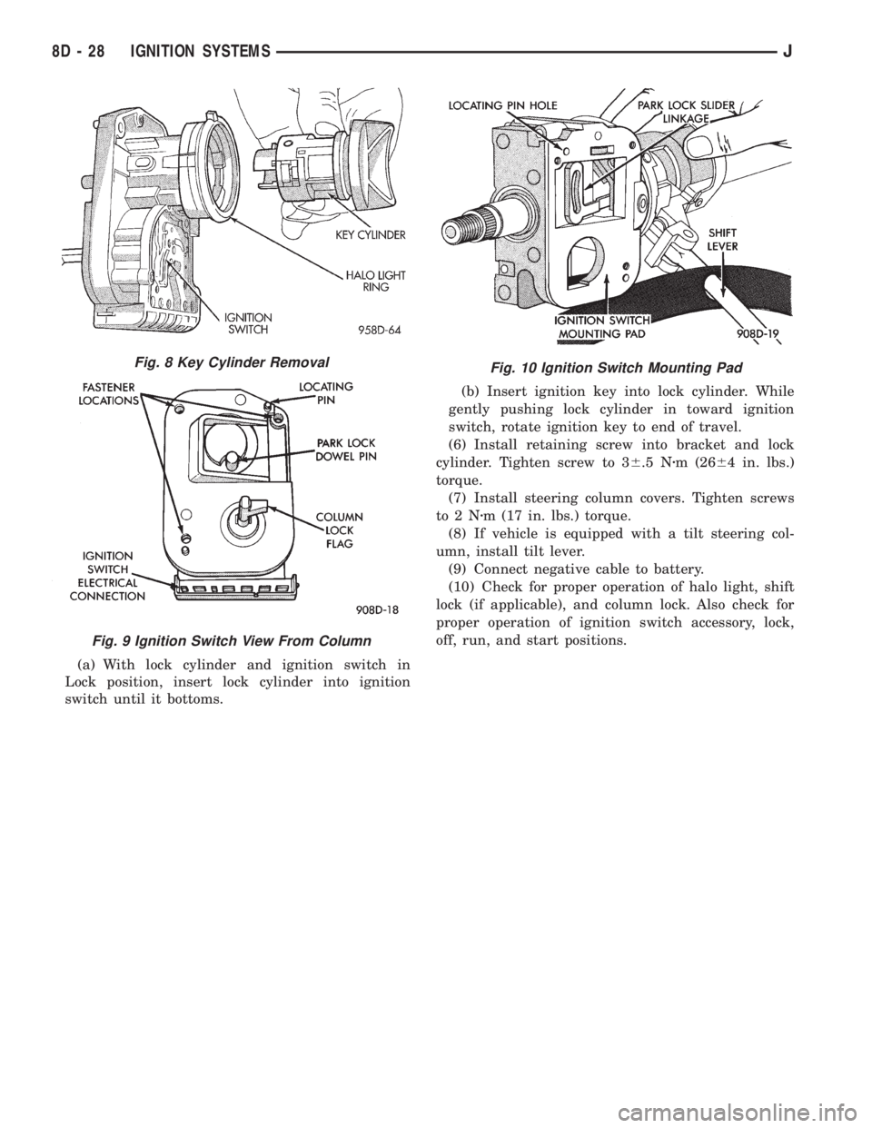
(a) With lock cylinder and ignition switch in
Lock position, insert lock cylinder into ignition
switch until it bottoms.(b) Insert ignition key into lock cylinder. While
gently pushing lock cylinder in toward ignition
switch, rotate ignition key to end of travel.
(6) Install retaining screw into bracket and lock
cylinder. Tighten screw to 36.5 Nzm (2664 in. lbs.)
torque.
(7) Install steering column covers. Tighten screws
to2Nzm (17 in. lbs.) torque.
(8) If vehicle is equipped with a tilt steering col-
umn, install tilt lever.
(9) Connect negative cable to battery.
(10) Check for proper operation of halo light, shift
lock (if applicable), and column lock. Also check for
proper operation of ignition switch accessory, lock,
off, run, and start positions.
Fig. 10 Ignition Switch Mounting PadFig. 8 Key Cylinder Removal
Fig. 9 Ignition Switch View From Column
8D - 28 IGNITION SYSTEMSJ
Page 342 of 2198
nition switch. Install screws finger tight. Remove the
dimmer switch actuator rod securing-tape from steer-
ing column.
(8) Adjust dimmer switch as follows: Depress the
switch slightly and insert a 3/32-inch drill bit into
the adjustment hole (Fig. 11). This is done to prevent
horizontal switch movement.
(9) Move switch toward steering wheel to remove
any lash from switch actuator rod. Tighten dimmer
and ignition switch fasteners to 4 Nzm (35 in. lbs.)
torque.(10) Install the windshield wiper intermittent con-
trol module and its bracket (if equipped).
(11) Install the negative battery cable.
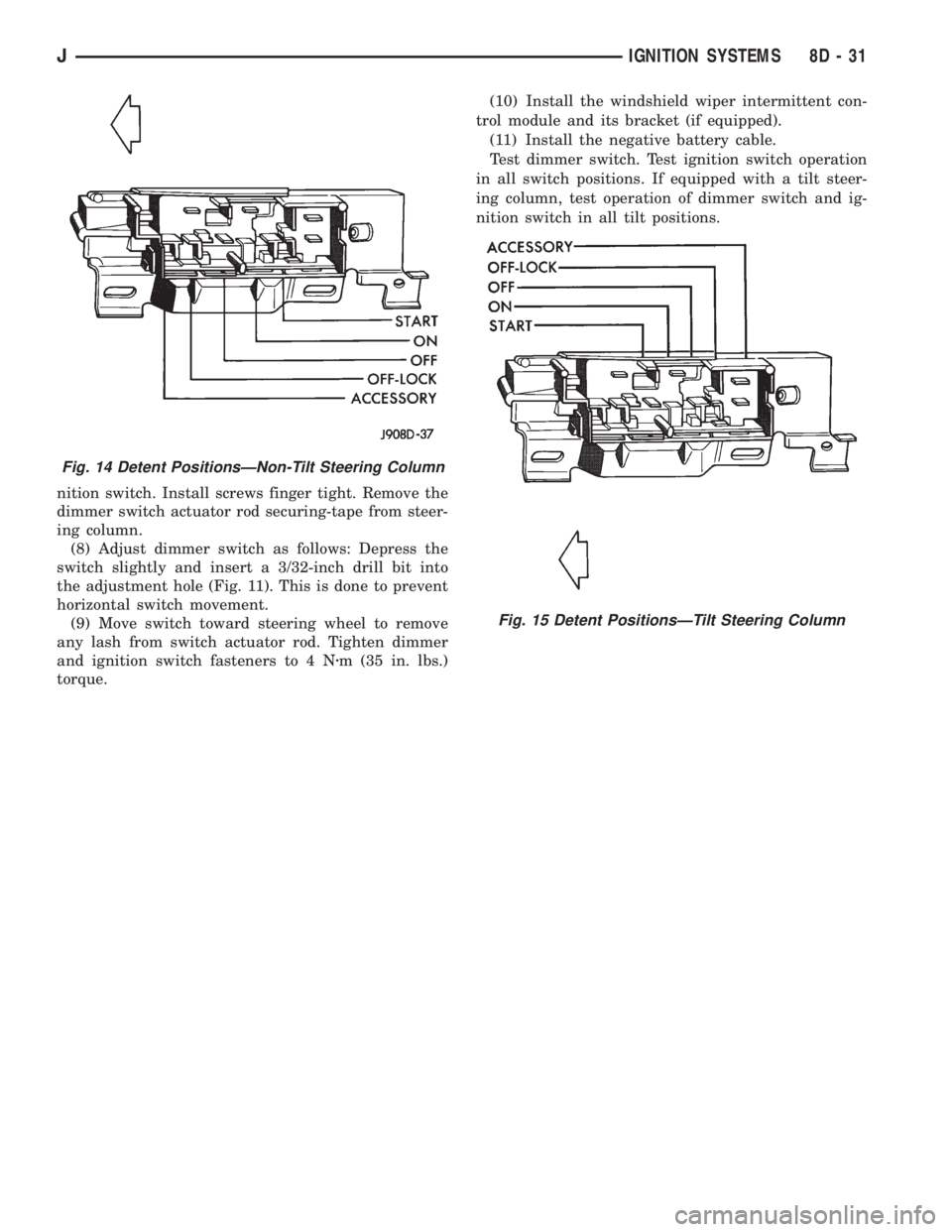
Test dimmer switch. Test ignition switch operation
in all switch positions. If equipped with a tilt steer-
ing column, test operation of dimmer switch and ig-
nition switch in all tilt positions.
Fig. 14 Detent PositionsÐNon-Tilt Steering Column
Fig. 15 Detent PositionsÐTilt Steering Column
JIGNITION SYSTEMS 8D - 31
Page 343 of 2198
SPECIFICATIONS
GENERAL INFORMATION
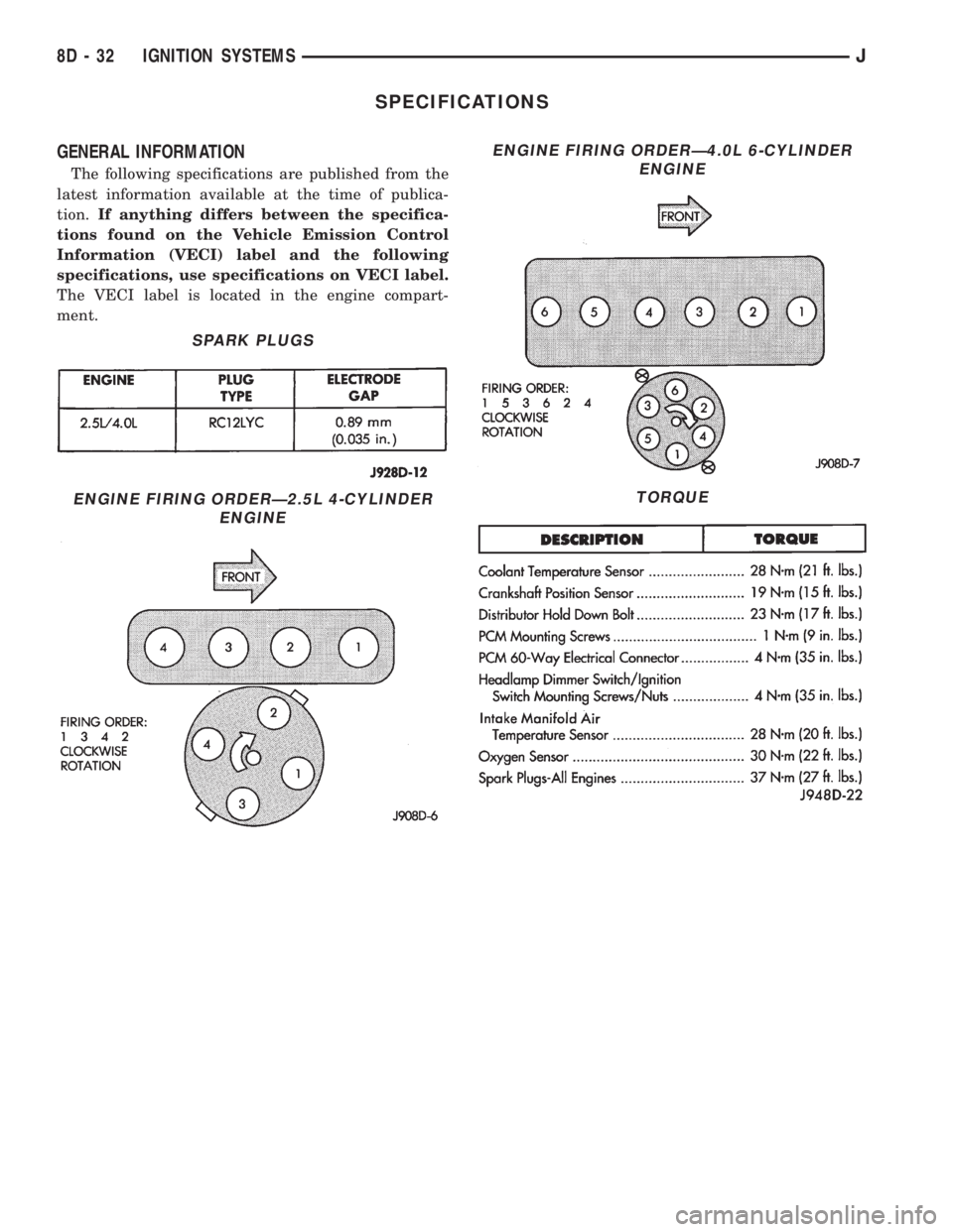
The following specifications are published from the
latest information available at the time of publica-
tion.If anything differs between the specifica-
tions found on the Vehicle Emission Control
Information (VECI) label and the following
specifications, use specifications on VECI label.
The VECI label is located in the engine compart-
ment.
SPARK PLUGS
ENGINE FIRING ORDERÐ2.5L 4-CYLINDER
ENGINE
ENGINE FIRING ORDERÐ4.0L 6-CYLINDER
ENGINE
TORQUE
8D - 32 IGNITION SYSTEMSJ
Page 427 of 2198
SERVICE PROCEDURES - XJ
WINDSHIELD WIPER MOTOR REMOVE/INSTALL
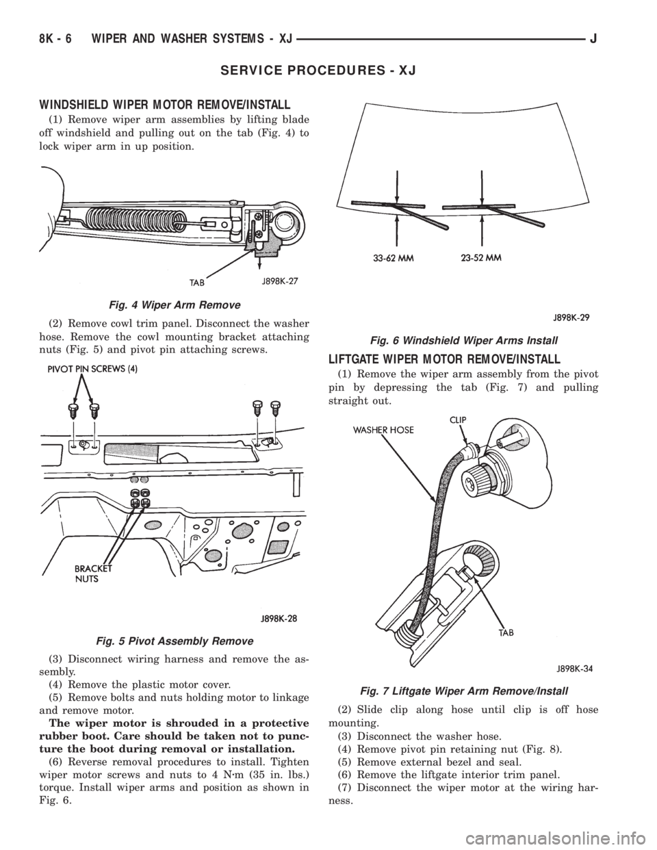
(1) Remove wiper arm assemblies by lifting blade
off windshield and pulling out on the tab (Fig. 4) to
lock wiper arm in up position.
(2) Remove cowl trim panel. Disconnect the washer
hose. Remove the cowl mounting bracket attaching
nuts (Fig. 5) and pivot pin attaching screws.
(3) Disconnect wiring harness and remove the as-
sembly.
(4) Remove the plastic motor cover.
(5) Remove bolts and nuts holding motor to linkage
and remove motor.
The wiper motor is shrouded in a protective
rubber boot. Care should be taken not to punc-
ture the boot during removal or installation.
(6) Reverse removal procedures to install. Tighten
wiper motor screws and nuts to 4 Nzm (35 in. lbs.)
torque. Install wiper arms and position as shown in
Fig. 6.
LIFTGATE WIPER MOTOR REMOVE/INSTALL
(1) Remove the wiper arm assembly from the pivot
pin by depressing the tab (Fig. 7) and pulling
straight out.
(2) Slide clip along hose until clip is off hose
mounting.
(3) Disconnect the washer hose.
(4) Remove pivot pin retaining nut (Fig. 8).
(5) Remove external bezel and seal.
(6) Remove the liftgate interior trim panel.
(7) Disconnect the wiper motor at the wiring har-
ness.
Fig. 4 Wiper Arm Remove
Fig. 5 Pivot Assembly Remove
Fig. 6 Windshield Wiper Arms Install
Fig. 7 Liftgate Wiper Arm Remove/Install
8K - 6 WIPER AND WASHER SYSTEMS - XJJ