1995 JEEP CHEROKEE torque
[x] Cancel search: torquePage 178 of 2198
(2) Align and attach harness connector to ECU.
Slide connector into engagement with tangs on ECU.
Then tilt connector downward and into engagement
with ECU pin terminals. Exercise care as pin termi-
nals can be damaged if connector is forced into place.
(3) Connect harness to security alarm module, if
equipped.
(4) Position ECU bracket under instrument panel.
(5) Install and tighten ECU mounting bracket
bolts/nuts to 8-14 Nzm (75- 125 in. lbs.) torque.
(6) Install trim panel on instrument panel, if re-
moved.
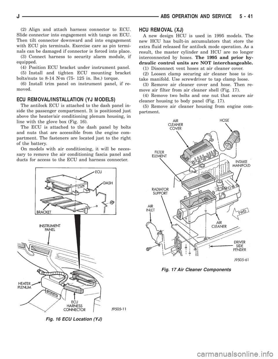
ECU REMOVAL/INSTALLATION (YJ MODELS)
The antilock ECU is attached to the dash panel in-
side the passenger compartment. It is positioned just
above the heater/air conditioning plenum housing, in
line with the glove box (Fig. 16).
The ECU is attached to the dash panel by bolts
and nuts that are accessible from the engine com-
partment. The fasteners are located just to the right
of the battery.
On models with air conditioning, it will be neces-
sary to remove the air conditioning fascia panel and
ducts for access to the ECU and harness connecter.
HCU REMOVAL (XJ)
A new design HCU is used in 1995 models. The
new HCU has built-in accumulators that store the
extra fluid released for antilock mode operation. As a
result, the master cylinder and HCU are no longer
interconnected by hoses.The 1995 and prior hy-
draulic control units are NOT interchangeable.
(1) Disconnect vent hoses at air cleaner cover.
(2) Loosen clamp securing air cleaner hose to in-
take manifold. Use screwdriver to tap clamp loose.
(3) Remove air cleaner cover and hose. Then re-
move air filter from air cleaner shell (Fig. 17).
(4) Remove two bolts and one nut that secure air
cleaner housing to body panel (Fig. 17).
(5) Remove air cleaner housing from engine com-
partment.
Fig. 16 ECU Location (YJ)
Fig. 17 Air Cleaner Components
JABS OPERATION AND SERVICE 5 - 41
Page 180 of 2198
HCU INSTALLATION (XJ)
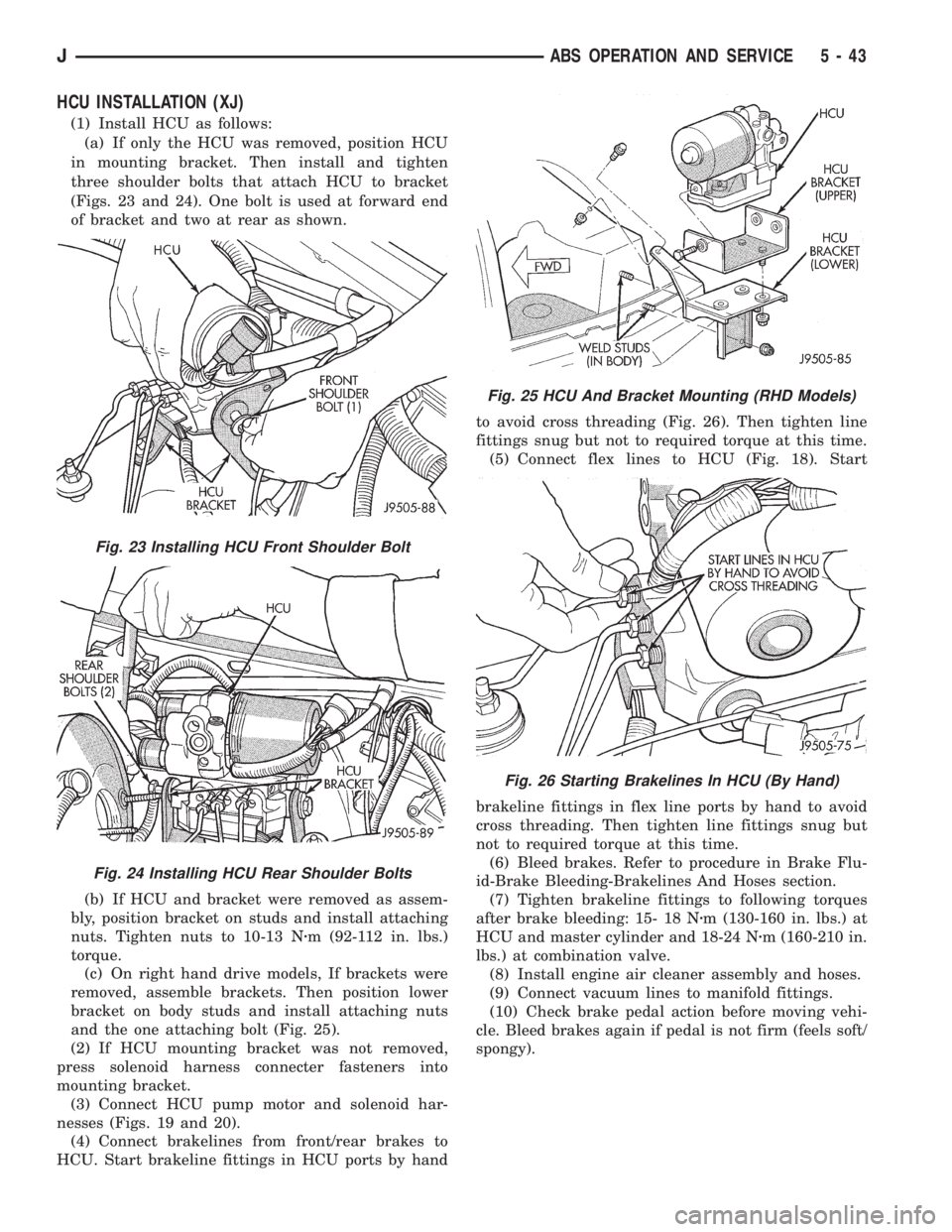
(1) Install HCU as follows:
(a) If only the HCU was removed, position HCU
in mounting bracket. Then install and tighten
three shoulder bolts that attach HCU to bracket
(Figs. 23 and 24). One bolt is used at forward end
of bracket and two at rear as shown.
(b) If HCU and bracket were removed as assem-
bly, position bracket on studs and install attaching
nuts. Tighten nuts to 10-13 Nzm (92-112 in. lbs.)
torque.
(c) On right hand drive models, If brackets were
removed, assemble brackets. Then position lower
bracket on body studs and install attaching nuts
and the one attaching bolt (Fig. 25).
(2) If HCU mounting bracket was not removed,
press solenoid harness connecter fasteners into
mounting bracket.
(3) Connect HCU pump motor and solenoid har-
nesses (Figs. 19 and 20).
(4) Connect brakelines from front/rear brakes to
HCU. Start brakeline fittings in HCU ports by handto avoid cross threading (Fig. 26). Then tighten line
fittings snug but not to required torque at this time.
(5) Connect flex lines to HCU (Fig. 18). Start
brakeline fittings in flex line ports by hand to avoid
cross threading. Then tighten line fittings snug but
not to required torque at this time.
(6) Bleed brakes. Refer to procedure in Brake Flu-
id-Brake Bleeding-Brakelines And Hoses section.
(7) Tighten brakeline fittings to following torques
after brake bleeding: 15- 18 Nzm (130-160 in. lbs.) at
HCU and master cylinder and 18-24 Nzm (160-210 in.
lbs.) at combination valve.
(8) Install engine air cleaner assembly and hoses.
(9) Connect vacuum lines to manifold fittings.
(10) Check brake pedal action before moving vehi-
cle. Bleed brakes again if pedal is not firm (feels soft/
spongy).
Fig. 23 Installing HCU Front Shoulder Bolt
Fig. 24 Installing HCU Rear Shoulder Bolts
Fig. 25 HCU And Bracket Mounting (RHD Models)
Fig. 26 Starting Brakelines In HCU (By Hand)
JABS OPERATION AND SERVICE 5 - 43
Page 181 of 2198
HCU REMOVAL (YJ)
(1) Place shop towels under master cylinder and
HCU brakelines.
(2) Disconnect flex lines at upper part of HCU.
(3) Disconnect solenoid and pump harness wires at
HCU harness connecters.
(4) Disconnect lines to front/rear brakes at lower
part of HCU.
(5) Remove shoulder bolts attaching HCU to
mounting bracket and remove HCU.
HCU INSTALLATION (YJ)
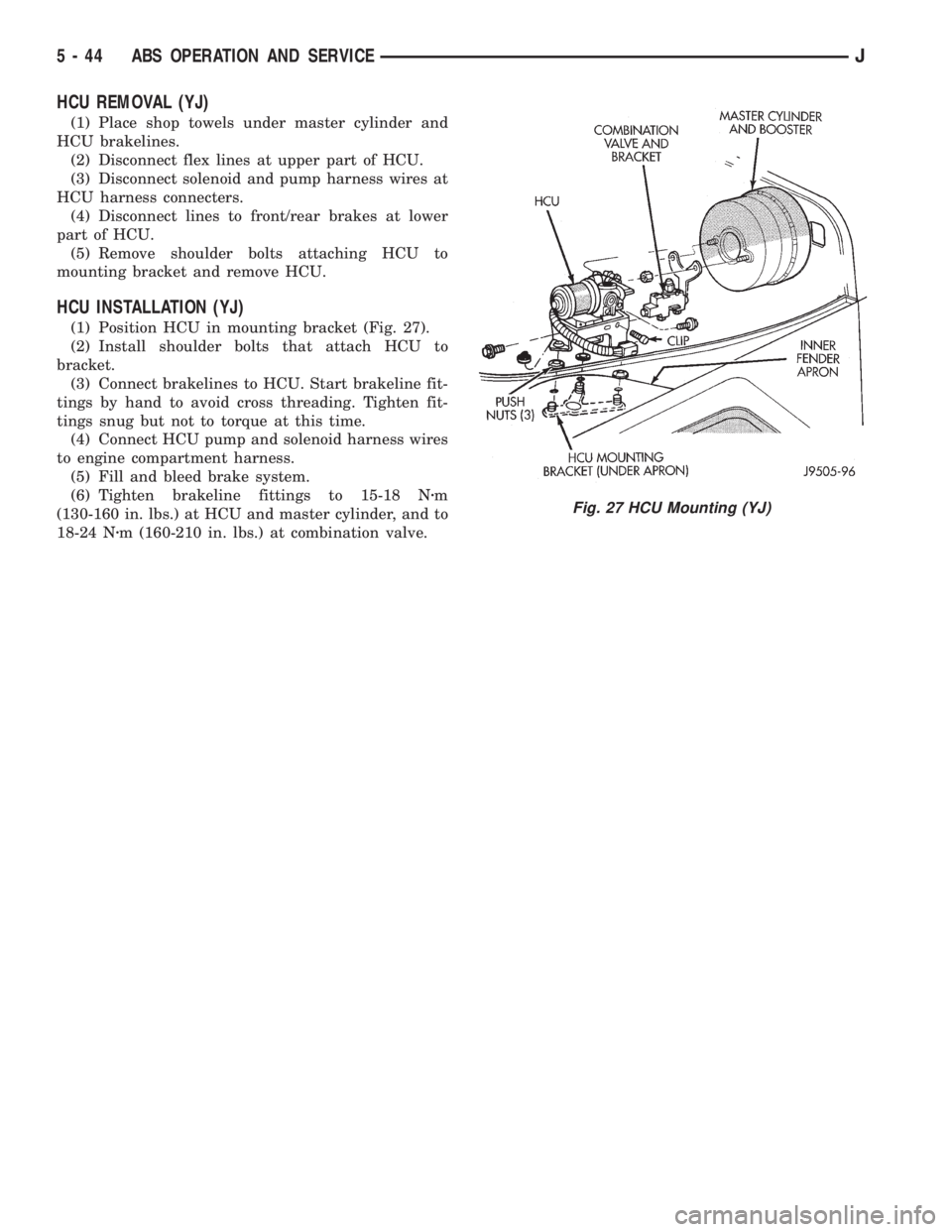
(1) Position HCU in mounting bracket (Fig. 27).
(2) Install shoulder bolts that attach HCU to
bracket.
(3) Connect brakelines to HCU. Start brakeline fit-
tings by hand to avoid cross threading. Tighten fit-
tings snug but not to torque at this time.
(4) Connect HCU pump and solenoid harness wires
to engine compartment harness.
(5) Fill and bleed brake system.
(6) Tighten brakeline fittings to 15-18 Nzm
(130-160 in. lbs.) at HCU and master cylinder, and to
18-24 Nzm (160-210 in. lbs.) at combination valve.
Fig. 27 HCU Mounting (YJ)
5 - 44 ABS OPERATION AND SERVICEJ
Page 185 of 2198
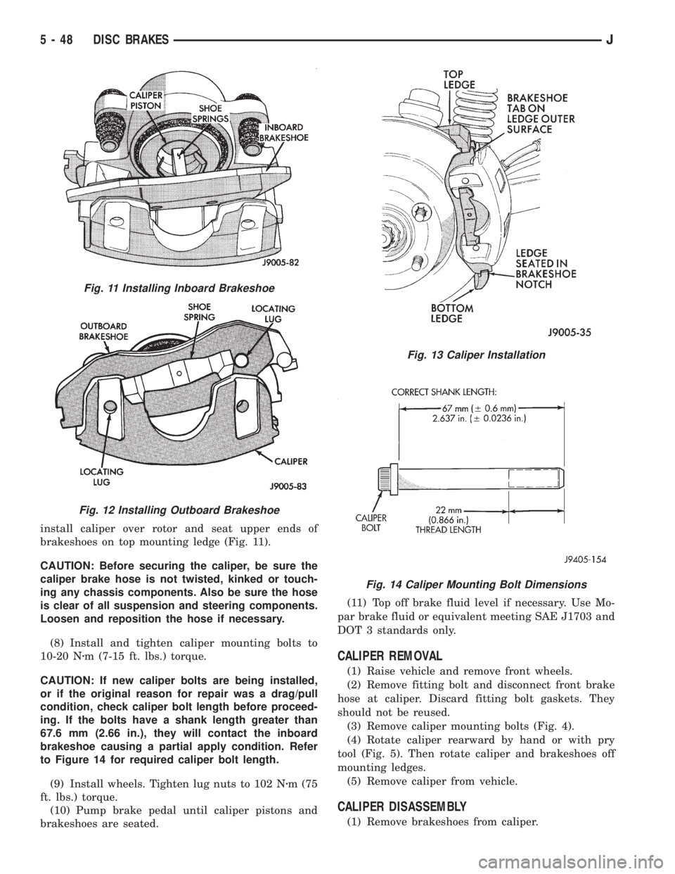
install caliper over rotor and seat upper ends of
brakeshoes on top mounting ledge (Fig. 11).
CAUTION: Before securing the caliper, be sure the
caliper brake hose is not twisted, kinked or touch-
ing any chassis components. Also be sure the hose
is clear of all suspension and steering components.
Loosen and reposition the hose if necessary.
(8) Install and tighten caliper mounting bolts to
10-20 Nzm (7-15 ft. lbs.) torque.
CAUTION: If new caliper bolts are being installed,
or if the original reason for repair was a drag/pull
condition, check caliper bolt length before proceed-
ing. If the bolts have a shank length greater than
67.6 mm (2.66 in.), they will contact the inboard
brakeshoe causing a partial apply condition. Refer
to Figure 14 for required caliper bolt length.
(9) Install wheels. Tighten lug nuts to 102 Nzm (75
ft. lbs.) torque.
(10) Pump brake pedal until caliper pistons and
brakeshoes are seated.(11) Top off brake fluid level if necessary. Use Mo-
par brake fluid or equivalent meeting SAE J1703 and
DOT 3 standards only.
CALIPER REMOVAL
(1) Raise vehicle and remove front wheels.
(2) Remove fitting bolt and disconnect front brake
hose at caliper. Discard fitting bolt gaskets. They
should not be reused.
(3) Remove caliper mounting bolts (Fig. 4).
(4) Rotate caliper rearward by hand or with pry
tool (Fig. 5). Then rotate caliper and brakeshoes off
mounting ledges.
(5) Remove caliper from vehicle.
CALIPER DISASSEMBLY
(1) Remove brakeshoes from caliper.
Fig. 11 Installing Inboard Brakeshoe
Fig. 12 Installing Outboard Brakeshoe
Fig. 13 Caliper Installation
Fig. 14 Caliper Mounting Bolt Dimensions
5 - 48 DISC BRAKESJ
Page 188 of 2198
CALIPER INSTALLATION
(1) Install brakeshoes in caliper (Figs. 11, 12).
(2) Connect brake hose to caliper but do not
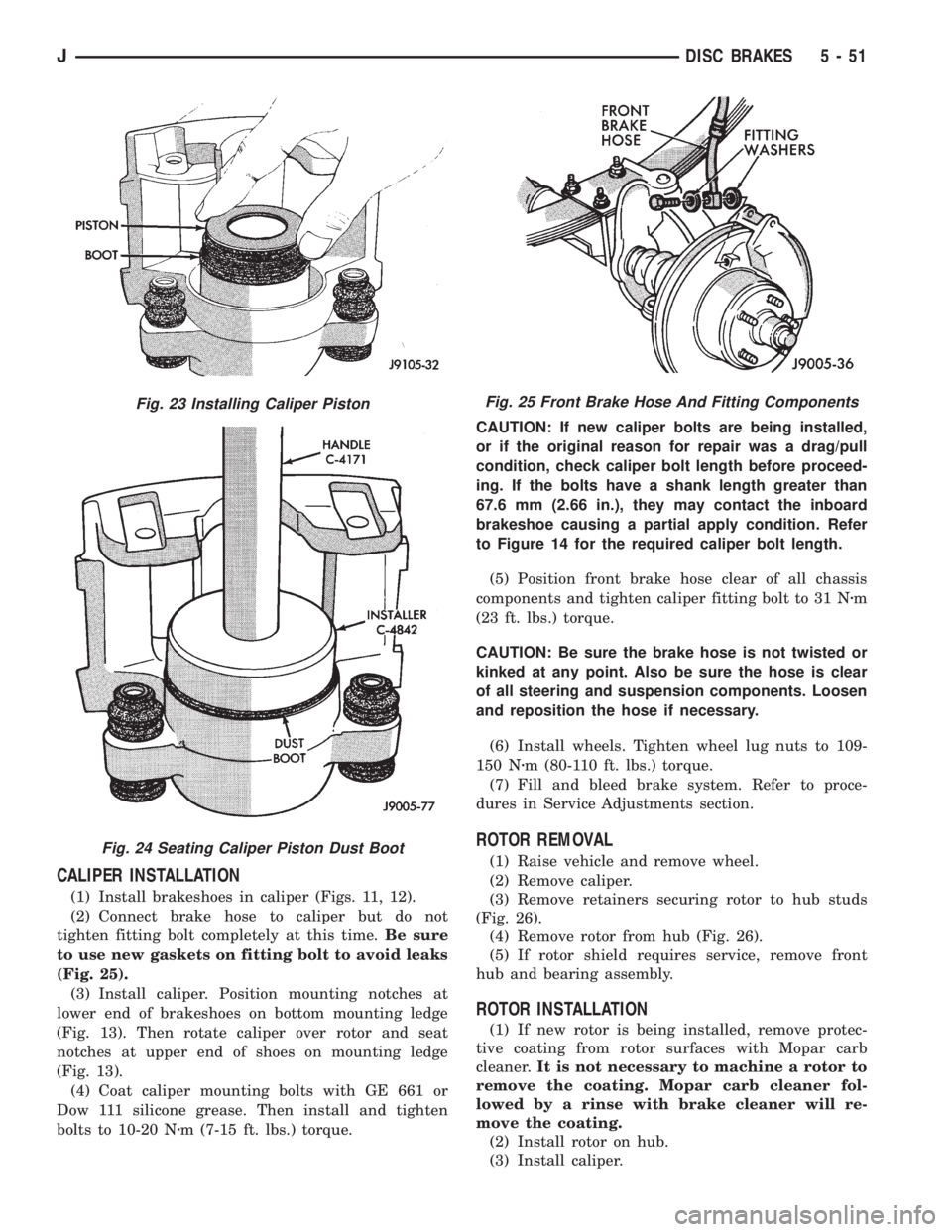
tighten fitting bolt completely at this time.Be sure
to use new gaskets on fitting bolt to avoid leaks
(Fig. 25).
(3) Install caliper. Position mounting notches at
lower end of brakeshoes on bottom mounting ledge
(Fig. 13). Then rotate caliper over rotor and seat
notches at upper end of shoes on mounting ledge
(Fig. 13).
(4) Coat caliper mounting bolts with GE 661 or
Dow 111 silicone grease. Then install and tighten
bolts to 10-20 Nzm (7-15 ft. lbs.) torque.CAUTION: If new caliper bolts are being installed,
or if the original reason for repair was a drag/pull
condition, check caliper bolt length before proceed-
ing. If the bolts have a shank length greater than
67.6 mm (2.66 in.), they may contact the inboard
brakeshoe causing a partial apply condition. Refer
to Figure 14 for the required caliper bolt length.
(5) Position front brake hose clear of all chassis
components and tighten caliper fitting bolt to 31 Nzm
(23 ft. lbs.) torque.
CAUTION: Be sure the brake hose is not twisted or
kinked at any point. Also be sure the hose is clear
of all steering and suspension components. Loosen
and reposition the hose if necessary.
(6) Install wheels. Tighten wheel lug nuts to 109-
150 Nzm (80-110 ft. lbs.) torque.
(7) Fill and bleed brake system. Refer to proce-
dures in Service Adjustments section.
ROTOR REMOVAL
(1) Raise vehicle and remove wheel.
(2) Remove caliper.
(3) Remove retainers securing rotor to hub studs
(Fig. 26).
(4) Remove rotor from hub (Fig. 26).
(5) If rotor shield requires service, remove front
hub and bearing assembly.
ROTOR INSTALLATION
(1) If new rotor is being installed, remove protec-
tive coating from rotor surfaces with Mopar carb
cleaner.It is not necessary to machine a rotor to
remove the coating. Mopar carb cleaner fol-
lowed by a rinse with brake cleaner will re-
move the coating.
(2) Install rotor on hub.
(3) Install caliper.
Fig. 23 Installing Caliper Piston
Fig. 24 Seating Caliper Piston Dust Boot
Fig. 25 Front Brake Hose And Fitting Components
JDISC BRAKES 5 - 51
Page 191 of 2198
WHEEL NUT TIGHTENING
The wheel attaching nuts must be tightened prop-
erly to ensure efficient brake operation. Overtighten-
ing the nuts or tightening them in the wrong
sequence can cause distortion of the brake rotors and
drums. Impact wrenches are not really recommended
for tightening wheel nuts. A torque wrench should be
used for this purpose.
A light coat of LPS Anti-Corrosion spray lube
around the hub face and on the studs will cut down
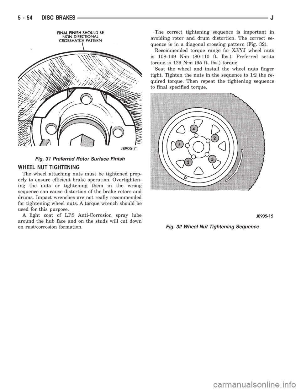
on rust/corrosion formation.The correct tightening sequence is important in
avoiding rotor and drum distortion. The correct se-
quence is in a diagonal crossing pattern (Fig. 32).
Recommended torque range for XJ/YJ wheel nuts
is 108-149 Nzm (80-110 ft. lbs.). Preferred set-to
torque is 129 Nzm (95 ft. lbs.) torque.
Seat the wheel and install the wheel nuts finger
tight. Tighten the nuts in the sequence to 1/2 the re-
quired torque. Then repeat the tightening sequence
to final specified torque.
Fig. 31 Preferred Rotor Surface Finish
Fig. 32 Wheel Nut Tightening Sequence
5 - 54 DISC BRAKESJ
Page 195 of 2198
Do not hone cylinder bores or polish pistons.
Replace cylinder as an assembly if bore is dam-
aged.
(8) Install bleed screw.
(9) Coat cylinder bore, pistons, cups and expander
with brake fluid and reassemble cylinder compo-
nents. Be sure piston cup lips face expander.
WHEEL CYLINDER INSTALLATION
(1) Apply small bead of silicone sealer around cyl-
inder mounting surface of support plate.
(2) Start brakeline in wheel cylinder fitting by
hand.
(3) Align and seat wheel cylinder on support plate
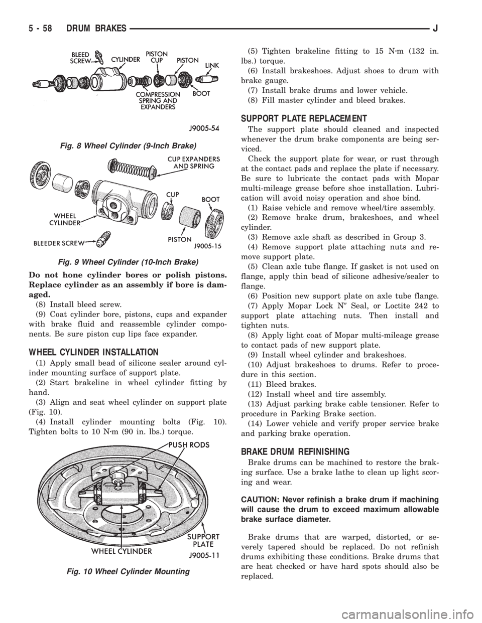
(Fig. 10).
(4) Install cylinder mounting bolts (Fig. 10).
Tighten bolts to 10 Nzm (90 in. lbs.) torque.(5) Tighten brakeline fitting to 15 Nzm (132 in.
lbs.) torque.
(6) Install brakeshoes. Adjust shoes to drum with
brake gauge.
(7) Install brake drums and lower vehicle.
(8) Fill master cylinder and bleed brakes.
SUPPORT PLATE REPLACEMENT
The support plate should cleaned and inspected
whenever the drum brake components are being ser-
viced.
Check the support plate for wear, or rust through
at the contact pads and replace the plate if necessary.
Be sure to lubricate the contact pads with Mopar
multi-mileage grease before shoe installation. Lubri-
cation will avoid noisy operation and shoe bind.
(1) Raise vehicle and remove wheel/tire assembly.
(2) Remove brake drum, brakeshoes, and wheel
cylinder.
(3) Remove axle shaft as described in Group 3.
(4) Remove support plate attaching nuts and re-
move support plate.
(5) Clean axle tube flange. If gasket is not used on
flange, apply thin bead of silicone adhesive/sealer to
flange.
(6) Position new support plate on axle tube flange.
(7) Apply Mopar Lock N9Seal, or Loctite 242 to
support plate attaching nuts. Then install and
tighten nuts.
(8) Apply light coat of Mopar multi-mileage grease
to contact pads of new support plate.
(9) Install wheel cylinder and brakeshoes.
(10) Adjust brakeshoes to drums. Refer to proce-
dure in this section.
(11) Bleed brakes.
(12) Install wheel and tire assembly.
(13) Adjust parking brake cable tensioner. Refer to
procedure in Parking Brake section.
(14) Lower vehicle and verify proper service brake
and parking brake operation.
BRAKE DRUM REFINISHING
Brake drums can be machined to restore the brak-
ing surface. Use a brake lathe to clean up light scor-
ing and wear.
CAUTION: Never refinish a brake drum if machining
will cause the drum to exceed maximum allowable
brake surface diameter.
Brake drums that are warped, distorted, or se-
verely tapered should be replaced. Do not refinish
drums exhibiting these conditions. Brake drums that
are heat checked or have hard spots should also be
replaced.
Fig. 8 Wheel Cylinder (9-Inch Brake)
Fig. 9 Wheel Cylinder (10-Inch Brake)
Fig. 10 Wheel Cylinder Mounting
5 - 58 DRUM BRAKESJ
Page 196 of 2198

If the brake drums are heavily coated with rust,
clean and inspect them carefully. Rust damage on
high mileage drums can be severe enough to require
replacement.
New drums have a protective coating that should
be removed before installation.It is not necessary
to machine a drum to remove this coating. The
coating is easily removed with Mopar carb
cleaner followed by a rinse with Mopar brake
cleaner. A scotch brite pad, or steel wool can
also be used to help loosen and remove the
coating if desired.
The maximum allowable diameter for the drum
braking surface is usually indicated on the drum
outer face (Fig. 11).
WHEEL NUT TIGHTENING
The wheel attaching lug nuts must be tightened
properly to ensure efficient brake operation. Over-tightening the nuts or tightening them in the wrong
sequence can cause distortion of the brake rotors and
drums.
Impact wrenches are not recommended for tighten-
ing wheel nuts. A torque wrench should be used for
this purpose.
A light coat of LPS Anti-Corrosion spray lube
around the hub face and on the studs will cut down
on rust/corrosion formation.
The correct tightening sequence is important in
avoiding rotor and drum distortion. The correct se-
quence is in a diagonal crossing pattern (Fig. 12).
Recommended torque range for XJ/YJ wheel nuts
is 109-150 Nzm (80-110 ft. lbs.).
Seat the wheel and install the wheel nuts finger
tight. Tighten the nuts in the sequence to half the re-
quired torque. Then repeat the tightening sequence
to final specified torque.
Fig. 11 Typical Location Of Brake Drum Refinish
Limit
Fig. 12 Wheel Nut Tightening Sequence
JDRUM BRAKES 5 - 59