1995 JEEP CHEROKEE torque
[x] Cancel search: torquePage 126 of 2198
CAUTION: Never loosen pinion gear nut to decrease
pinion gear bearing preload torque and never ex-
ceed specified preload torque. If preload torque is
exceeded a new collapsible spacer must be in-
stalled. The torque sequence will have to be re-
peated.
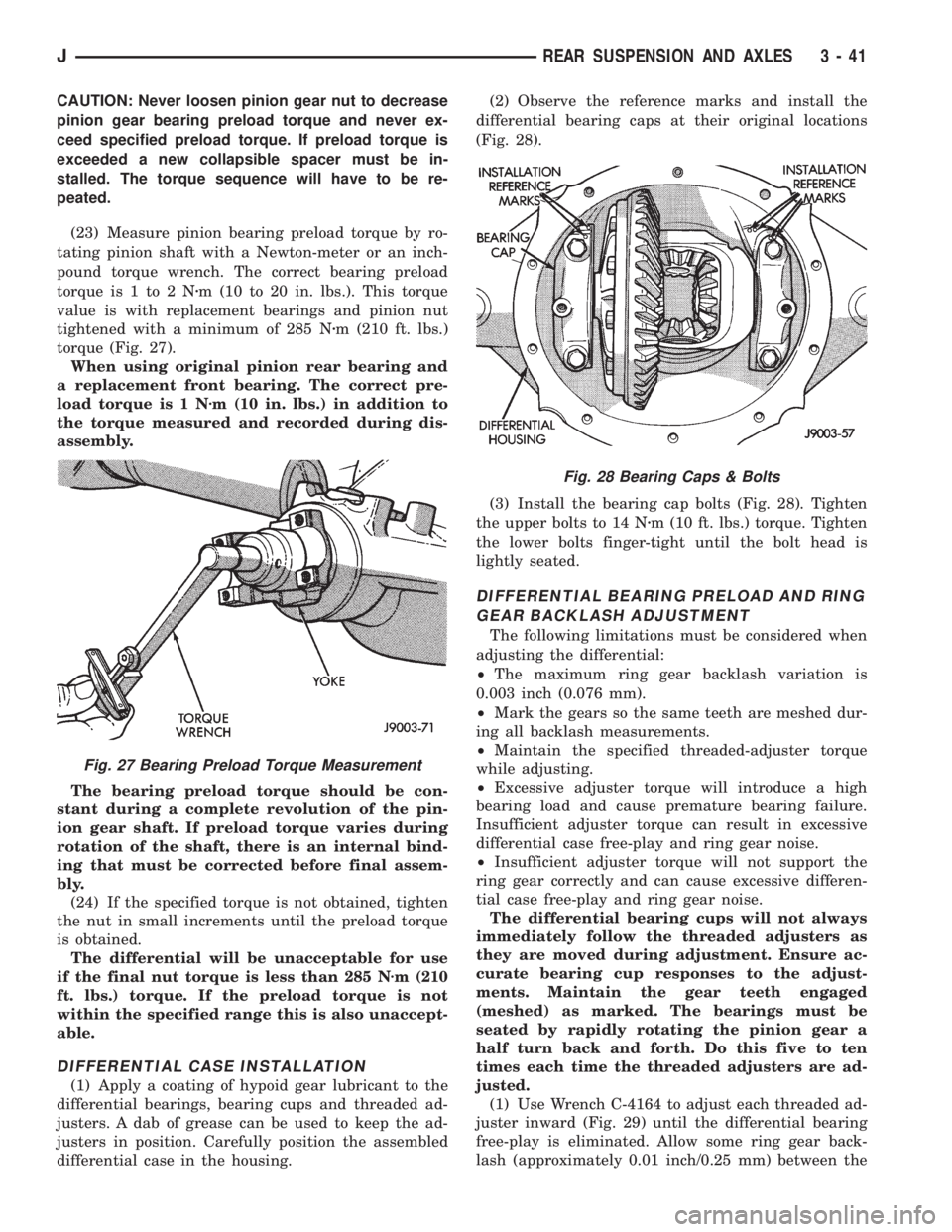
(23) Measure pinion bearing preload torque by ro-
tating pinion shaft with a Newton-meter or an inch-
pound torque wrench. The correct bearing preload
torque is 1 to 2 Nzm (10 to 20 in. lbs.). This torque
value is with replacement bearings and pinion nut
tightened with a minimum of 285 Nzm (210 ft. lbs.)
torque (Fig. 27).
When using original pinion rear bearing and
a replacement front bearing. The correct pre-
load torque is 1 Nzm (10 in. lbs.) in addition to
the torque measured and recorded during dis-
assembly.
The bearing preload torque should be con-
stant during a complete revolution of the pin-
ion gear shaft. If preload torque varies during
rotation of the shaft, there is an internal bind-
ing that must be corrected before final assem-
bly.
(24) If the specified torque is not obtained, tighten
the nut in small increments until the preload torque
is obtained.
The differential will be unacceptable for use
if the final nut torque is less than 285 Nzm (210
ft. lbs.) torque. If the preload torque is not
within the specified range this is also unaccept-
able.
DIFFERENTIAL CASE INSTALLATION
(1) Apply a coating of hypoid gear lubricant to the
differential bearings, bearing cups and threaded ad-
justers. A dab of grease can be used to keep the ad-
justers in position. Carefully position the assembled
differential case in the housing.(2) Observe the reference marks and install the
differential bearing caps at their original locations
(Fig. 28).
(3) Install the bearing cap bolts (Fig. 28). Tighten
the upper bolts to 14 Nzm (10 ft. lbs.) torque. Tighten
the lower bolts finger-tight until the bolt head is
lightly seated.
DIFFERENTIAL BEARING PRELOAD AND RING
GEAR BACKLASH ADJUSTMENT
The following limitations must be considered when
adjusting the differential:
²The maximum ring gear backlash variation is
0.003 inch (0.076 mm).
²Mark the gears so the same teeth are meshed dur-
ing all backlash measurements.
²Maintain the specified threaded-adjuster torque
while adjusting.
²Excessive adjuster torque will introduce a high
bearing load and cause premature bearing failure.
Insufficient adjuster torque can result in excessive
differential case free-play and ring gear noise.
²Insufficient adjuster torque will not support the
ring gear correctly and can cause excessive differen-
tial case free-play and ring gear noise.
The differential bearing cups will not always
immediately follow the threaded adjusters as
they are moved during adjustment. Ensure ac-
curate bearing cup responses to the adjust-
ments. Maintain the gear teeth engaged
(meshed) as marked. The bearings must be
seated by rapidly rotating the pinion gear a
half turn back and forth. Do this five to ten
times each time the threaded adjusters are ad-
justed.
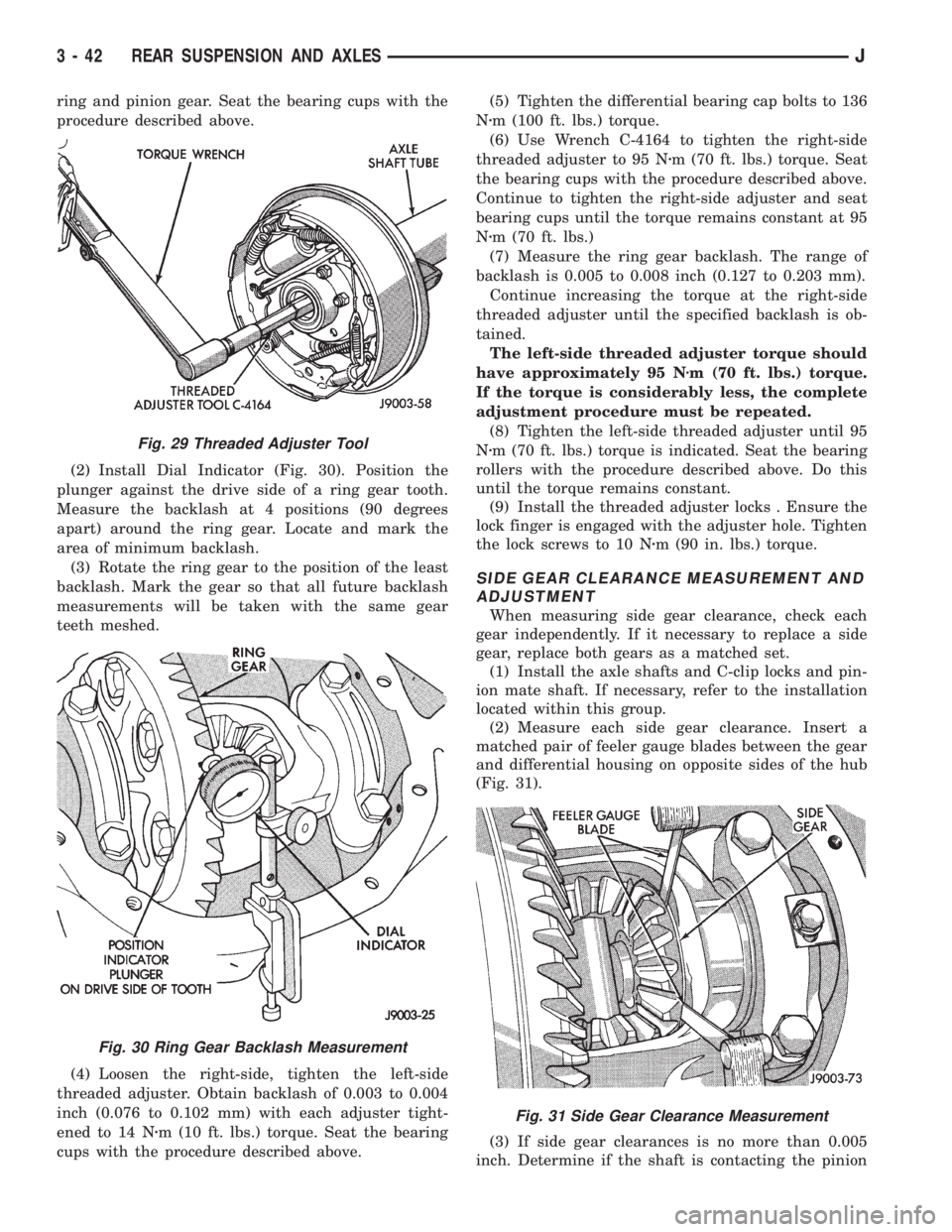
(1) Use Wrench C-4164 to adjust each threaded ad-
juster inward (Fig. 29) until the differential bearing
free-play is eliminated. Allow some ring gear back-
lash (approximately 0.01 inch/0.25 mm) between the
Fig. 27 Bearing Preload Torque Measurement
Fig. 28 Bearing Caps & Bolts
JREAR SUSPENSION AND AXLES 3 - 41
Page 127 of 2198
ring and pinion gear. Seat the bearing cups with the
procedure described above.
(2) Install Dial Indicator (Fig. 30). Position the
plunger against the drive side of a ring gear tooth.
Measure the backlash at 4 positions (90 degrees
apart) around the ring gear. Locate and mark the
area of minimum backlash.
(3) Rotate the ring gear to the position of the least
backlash. Mark the gear so that all future backlash
measurements will be taken with the same gear
teeth meshed.
(4) Loosen the right-side, tighten the left-side
threaded adjuster. Obtain backlash of 0.003 to 0.004
inch (0.076 to 0.102 mm) with each adjuster tight-
ened to 14 Nzm (10 ft. lbs.) torque. Seat the bearing
cups with the procedure described above.(5) Tighten the differential bearing cap bolts to 136
Nzm (100 ft. lbs.) torque.
(6) Use Wrench C-4164 to tighten the right-side
threaded adjuster to 95 Nzm (70 ft. lbs.) torque. Seat
the bearing cups with the procedure described above.
Continue to tighten the right-side adjuster and seat
bearing cups until the torque remains constant at 95
Nzm (70 ft. lbs.)
(7) Measure the ring gear backlash. The range of
backlash is 0.005 to 0.008 inch (0.127 to 0.203 mm).
Continue increasing the torque at the right-side
threaded adjuster until the specified backlash is ob-
tained.
The left-side threaded adjuster torque should
have approximately 95 Nzm (70 ft. lbs.) torque.
If the torque is considerably less, the complete
adjustment procedure must be repeated.
(8) Tighten the left-side threaded adjuster until 95
Nzm (70 ft. lbs.) torque is indicated. Seat the bearing
rollers with the procedure described above. Do this
until the torque remains constant.
(9) Install the threaded adjuster locks . Ensure the
lock finger is engaged with the adjuster hole. Tighten
the lock screws to 10 Nzm (90 in. lbs.) torque.
SIDE GEAR CLEARANCE MEASUREMENT AND
ADJUSTMENT
When measuring side gear clearance, check each
gear independently. If it necessary to replace a side
gear, replace both gears as a matched set.
(1) Install the axle shafts and C-clip locks and pin-
ion mate shaft. If necessary, refer to the installation
located within this group.
(2) Measure each side gear clearance. Insert a
matched pair of feeler gauge blades between the gear
and differential housing on opposite sides of the hub
(Fig. 31).
(3) If side gear clearances is no more than 0.005
inch. Determine if the shaft is contacting the pinion
Fig. 29 Threaded Adjuster Tool
Fig. 30 Ring Gear Backlash Measurement
Fig. 31 Side Gear Clearance Measurement
3 - 42 REAR SUSPENSION AND AXLESJ
Page 130 of 2198
TRAC-LOK DIFFERENTIAL
OPERATION
In a conventional differential, the torque applied to
the ring gear is transmitted to the axle shafts through
the differential gears. During normal operation, the
torque transmitted to each wheel is equal at all times.
However, if one wheel spins, the opposite wheel will
generate only as much torque as the spinning wheel.
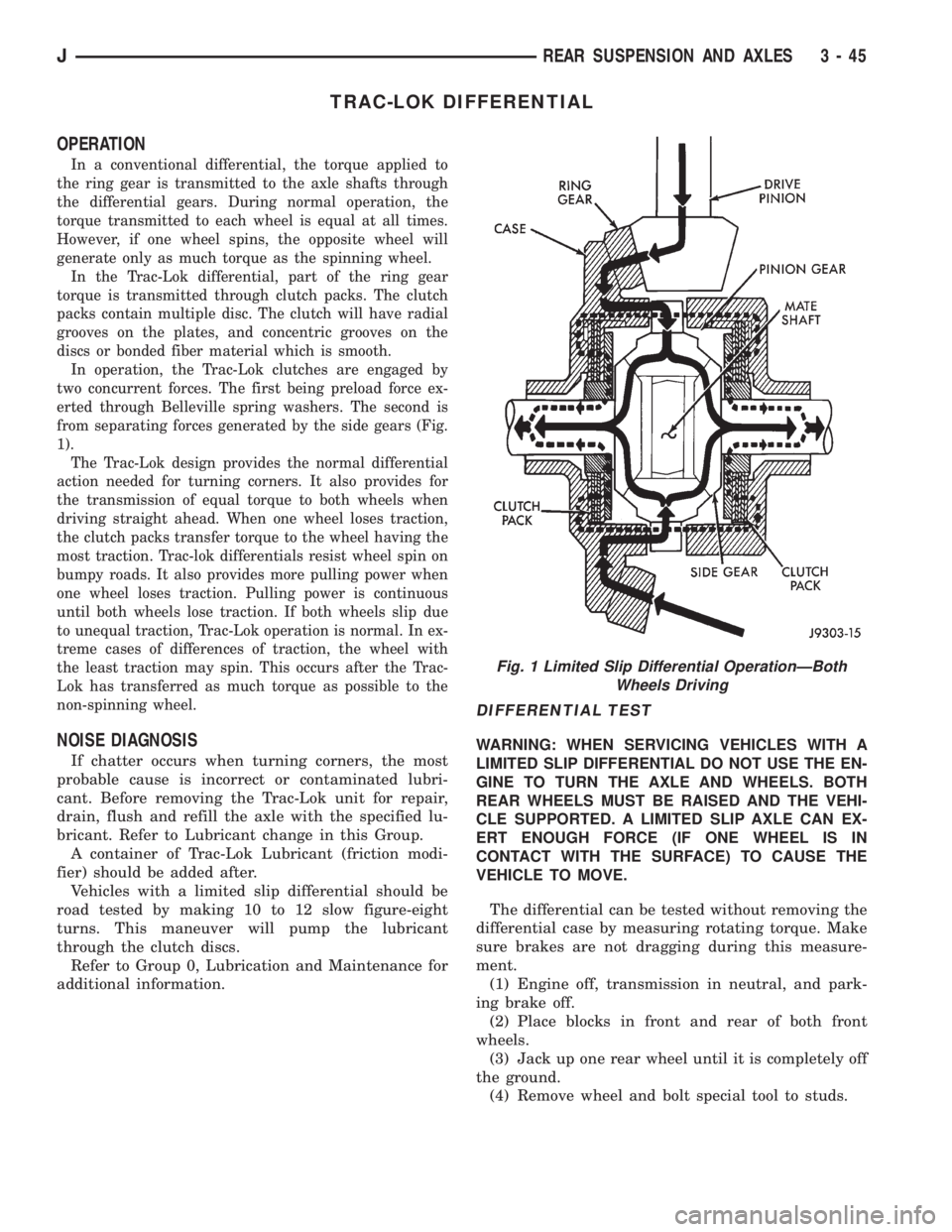
In the Trac-Lok differential, part of the ring gear
torque is transmitted through clutch packs. The clutch
packs contain multiple disc. The clutch will have radial
grooves on the plates, and concentric grooves on the
discs or bonded fiber material which is smooth.
In operation, the Trac-Lok clutches are engaged by
two concurrent forces. The first being preload force ex-
erted through Belleville spring washers. The second is
from separating forces generated by the side gears (Fig.
1).
The Trac-Lok design provides the normal differential
action needed for turning corners. It also provides for
the transmission of equal torque to both wheels when
driving straight ahead. When one wheel loses traction,
the clutch packs transfer torque to the wheel having the
most traction. Trac-lok differentials resist wheel spin on
bumpy roads. It also provides more pulling power when
one wheel loses traction. Pulling power is continuous
until both wheels lose traction. If both wheels slip due
to unequal traction, Trac-Lok operation is normal. In ex-
treme cases of differences of traction, the wheel with
the least traction may spin. This occurs after the Trac-
Lok has transferred as much torque as possible to the
non-spinning wheel.
NOISE DIAGNOSIS
If chatter occurs when turning corners, the most
probable cause is incorrect or contaminated lubri-
cant. Before removing the Trac-Lok unit for repair,
drain, flush and refill the axle with the specified lu-
bricant. Refer to Lubricant change in this Group.
A container of Trac-Lok Lubricant (friction modi-
fier) should be added after.
Vehicles with a limited slip differential should be
road tested by making 10 to 12 slow figure-eight
turns. This maneuver will pump the lubricant
through the clutch discs.
Refer to Group 0, Lubrication and Maintenance for
additional information.
DIFFERENTIAL TEST
WARNING: WHEN SERVICING VEHICLES WITH A
LIMITED SLIP DIFFERENTIAL DO NOT USE THE EN-
GINE TO TURN THE AXLE AND WHEELS. BOTH
REAR WHEELS MUST BE RAISED AND THE VEHI-
CLE SUPPORTED. A LIMITED SLIP AXLE CAN EX-
ERT ENOUGH FORCE (IF ONE WHEEL IS IN
CONTACT WITH THE SURFACE) TO CAUSE THE
VEHICLE TO MOVE.
The differential can be tested without removing the
differential case by measuring rotating torque. Make
sure brakes are not dragging during this measure-
ment.
(1) Engine off, transmission in neutral, and park-
ing brake off.
(2) Place blocks in front and rear of both front
wheels.
(3) Jack up one rear wheel until it is completely off
the ground.
(4) Remove wheel and bolt special tool to studs.
Fig. 1 Limited Slip Differential OperationÐBoth
Wheels Driving
JREAR SUSPENSION AND AXLES 3 - 45
Page 131 of 2198
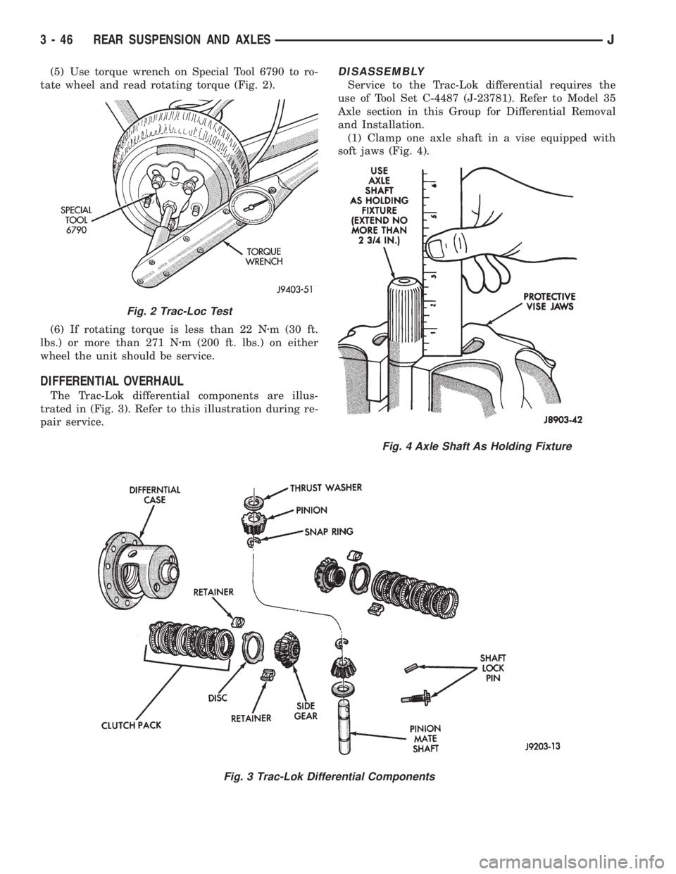
(5) Use torque wrench on Special Tool 6790 to ro-
tate wheel and read rotating torque (Fig. 2).
(6) If rotating torque is less than 22 Nzm (30 ft.
lbs.) or more than 271 Nzm (200 ft. lbs.) on either
wheel the unit should be service.
DIFFERENTIAL OVERHAUL
The Trac-Lok differential components are illus-
trated in (Fig. 3). Refer to this illustration during re-
pair service.
DISASSEMBLY
Service to the Trac-Lok differential requires the
use of Tool Set C-4487 (J-23781). Refer to Model 35
Axle section in this Group for Differential Removal
and Installation.
(1) Clamp one axle shaft in a vise equipped with
soft jaws (Fig. 4).
Fig. 3 Trac-Lok Differential Components
Fig. 2 Trac-Loc Test
Fig. 4 Axle Shaft As Holding Fixture
3 - 46 REAR SUSPENSION AND AXLESJ
Page 135 of 2198
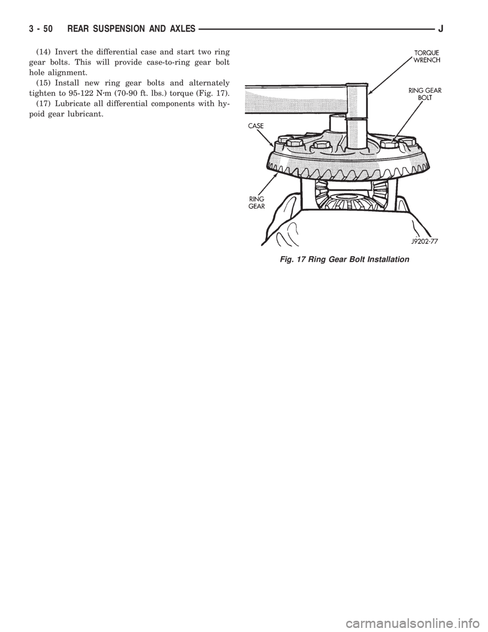
(14) Invert the differential case and start two ring
gear bolts. This will provide case-to-ring gear bolt
hole alignment.
(15) Install new ring gear bolts and alternately
tighten to 95-122 Nzm (70-90 ft. lbs.) torque (Fig. 17).
(17) Lubricate all differential components with hy-
poid gear lubricant.
Fig. 17 Ring Gear Bolt Installation
3 - 50 REAR SUSPENSION AND AXLESJ
Page 136 of 2198
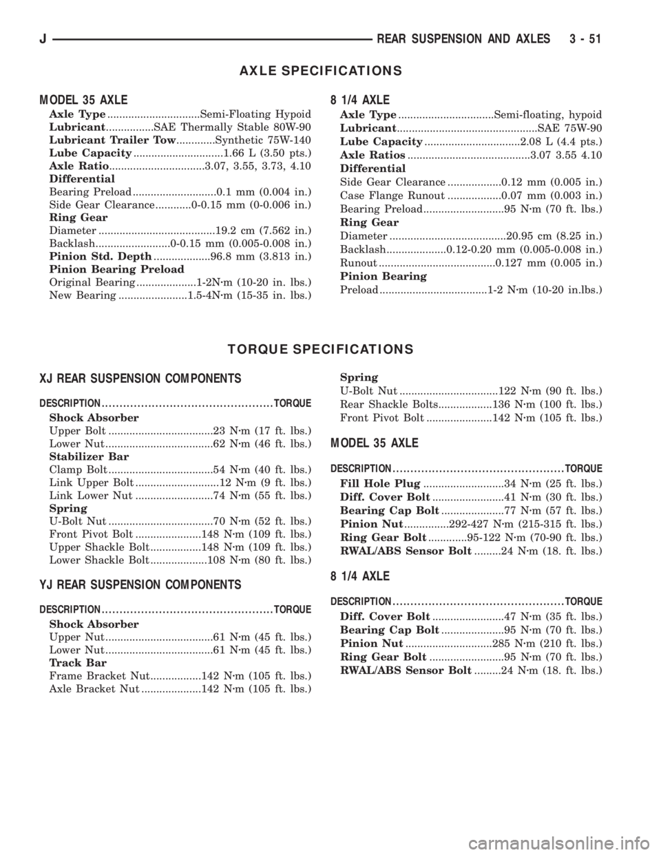
AXLE SPECIFICATIONS
MODEL 35 AXLE
Axle Type...............................Semi-Floating Hypoid
Lubricant................SAE Thermally Stable 80W-90
Lubricant Trailer Tow.............Synthetic 75W-140
Lube Capacity..............................1.66 L (3.50 pts.)
Axle Ratio................................3.07, 3.55, 3.73, 4.10
Differential
Bearing Preload ............................0.1 mm (0.004 in.)
Side Gear Clearance ............0-0.15 mm (0-0.006 in.)
Ring Gear
Diameter .......................................19.2 cm (7.562 in.)
Backlash.........................0-0.15 mm (0.005-0.008 in.)
Pinion Std. Depth...................96.8 mm (3.813 in.)
Pinion Bearing Preload
Original Bearing ....................1-2Nzm (10-20 in. lbs.)
New Bearing .......................1.5-4Nzm (15-35 in. lbs.)
8 1/4 AXLE
Axle Type................................Semi-floating, hypoid
Lubricant...............................................SAE 75W-90
Lube Capacity................................2.08 L (4.4 pts.)
Axle Ratios.........................................3.07 3.55 4.10
Differential
Side Gear Clearance ..................0.12 mm (0.005 in.)
Case Flange Runout ..................0.07 mm (0.003 in.)
Bearing Preload ...........................95 Nzm (70 ft. lbs.)
Ring Gear
Diameter .......................................20.95 cm (8.25 in.)
Backlash....................0.12-0.20 mm (0.005-0.008 in.)
Runout .......................................0.127 mm (0.005 in.)
Pinion Bearing
Preload ....................................1-2 Nzm (10-20 in.lbs.)
TORQUE SPECIFICATIONS
XJ REAR SUSPENSION COMPONENTS
DESCRIPTION ................................................TORQUE
Shock Absorber
Upper Bolt ...................................23 Nzm (17 ft. lbs.)
Lower Nut ....................................62 Nzm (46 ft. lbs.)
Stabilizer Bar
Clamp Bolt ...................................54 Nzm (40 ft. lbs.)
Link Upper Bolt ............................12 Nzm (9 ft. lbs.)
Link Lower Nut ..........................74 Nzm (55 ft. lbs.)
Spring
U-Bolt Nut ...................................70 Nzm (52 ft. lbs.)
Front Pivot Bolt ......................148 Nzm (109 ft. lbs.)
Upper Shackle Bolt .................148 Nzm (109 ft. lbs.)
Lower Shackle Bolt ...................108 Nzm (80 ft. lbs.)
YJ REAR SUSPENSION COMPONENTS
DESCRIPTION ................................................TORQUE
Shock Absorber
Upper Nut ....................................61 Nzm (45 ft. lbs.)
Lower Nut ....................................61 Nzm (45 ft. lbs.)
Track Bar
Frame Bracket Nut.................142 Nzm (105 ft. lbs.)
Axle Bracket Nut ....................142 Nzm (105 ft. lbs.)Spring
U-Bolt Nut .................................122 Nzm (90 ft. lbs.)
Rear Shackle Bolts..................136 Nzm (100 ft. lbs.)
Front Pivot Bolt ......................142 Nzm (105 ft. lbs.)
MODEL 35 AXLE
DESCRIPTION ................................................TORQUE
Fill Hole Plug...........................34 Nzm (25 ft. lbs.)
Diff. Cover Bolt........................41 Nzm (30 ft. lbs.)
Bearing Cap Bolt.....................77 Nzm (57 ft. lbs.)
Pinion Nut...............292-427 Nzm (215-315 ft. lbs.)
Ring Gear Bolt.............95-122 Nzm (70-90 ft. lbs.)
RWAL/ABS Sensor Bolt.........24 Nzm (18. ft. lbs.)
8 1/4 AXLE
DESCRIPTION ................................................TORQUE
Diff. Cover Bolt........................47 Nzm (35 ft. lbs.)
Bearing Cap Bolt.....................95 Nzm (70 ft. lbs.)
Pinion Nut.............................285 Nzm (210 ft. lbs.)
Ring Gear Bolt.........................95 Nzm (70 ft. lbs.)
RWAL/ABS Sensor Bolt.........24 Nzm (18. ft. lbs.)
JREAR SUSPENSION AND AXLES 3 - 51
Page 143 of 2198
pedal. The proper course of action is to bleed the sys-
tem, or replace thin drums and suspect quality brake
lines and hoses.
HARD PEDAL OR HIGH PEDAL EFFORT
A hard pedal or high pedal effort may be due to lin-
ing that is water soaked, contaminated, glazed, or
badly worn. The power booster or check valve could
also be faulty. Test the booster and valve as described
in this section.
BRAKE DRAG
Brake drag occurs when the lining is in constant
contact with the rotor or drum. Drag can occur at one
wheel, all wheels, fronts only, or rears only. It is a
product of incomplete brakeshoe release. Drag can be
minor or severe enough to overheat the linings, ro-
tors and drums. A drag condition also worsens as
temperature of the brake parts increases.
Brake drag also has a direct effect on fuel economy.
If undetected, minor brake drag can be misdiagnosed
as an engine or transmission/torque converter prob-
lem.
Minor drag will usually cause slight surface char-
ring of the lining. It can also generate hard spots in
rotors and drums from the overheat/cool down pro-
cess. In most cases, the rotors, drums, wheels and
tires are quite warm to the touch after the vehicle is
stopped.
Severe drag can char the brake lining all the way
through. It can also distort and score rotors and
drums to the point of replacement. The wheels, tires
and brake components will be extremely hot. In se-
vere cases, the lining may generate smoke as it chars
from overheating.
An additional cause of drag involves the use of in-
correct length caliper mounting bolts. Bolts that are
too long can cause a partial apply condition. The cor-
rect caliper bolts have a shank length of 67 mm
(2.637 in.), plus or minus 0.6 mm (0.0236 in.). Refer
to the Disc Brake service section for more detail on
caliper bolt dimensions and identification.
Some common causes of brake drag are:
²loose or damaged wheel bearing
²seized or sticking caliper or wheel cylinder piston
²caliper binding on bolts or slide surfaces
²wrong length caliper mounting bolts (too long)
²loose caliper mounting bracket
²distorted rotor, brake drum, or shoes
²brakeshoes binding on worn/damaged support
plates
²severely rusted/corroded components
²misassembled components.
If brake drag occurs at all wheels, the problem may
be related to a blocked master cylinder compensatorport or faulty power booster (binds-does not release).
The condition will worsen as brake temperature in-
creases.
The brakelight switch can also be a cause of drag.
An improperly mounted or adjusted brakelight
switch can prevent full brake pedal return. The re-
sult will be the same as if the master cylinder com-
pensator ports are blocked. The brakes would be
partially applied causing drag.
BRAKE FADE
Brake fade is a product of overheating caused by
brake drag. However, overheating and subsequent
fade can also be caused by riding the brake pedal,
making repeated high deceleration stops in a short
time span, or constant braking on steep roads. Refer
to the Brake Drag information in this section for
causes.
PEDAL PULSATION (NON-ABS BRAKES ONLY)
Pedal pulsation is caused by parts that are loose,
or beyond tolerance limits. This type of pulsation is
constant and will occur every time the brakes are ap-
plied.
Disc brake rotors with excessive lateral runout or
thickness variation, or out of round brake drums are
the primary causes of pulsation.
On vehicles with ABS brakes, remember that pedal
pulsation is normal during antilock mode brake
stops. If pulsation occurs during light to moderate
brake stops, a standard brake part is either loose, or
worn beyond tolerance.
BRAKE PULL
A front pull condition could be the result of:
²contaminated lining in one caliper
²seized caliper piston
²binding caliper
²wrong caliper mounting bolts (too long)
²loose caliper
²loose or corroded mounting bolts
²improper brakeshoes
²damaged rotor
²incorrect wheel bearing adjustment (at one wheel)
A worn, damaged wheel bearing or suspension com-
ponent are further causes of pull. A damaged front
tire (bruised, ply separation) can also cause pull.
Wrong caliper bolts (too long) will cause a partial ap-
ply condition and pull if only one caliper is involved.
A common and frequently misdiagnosed pull condi-
tion is where direction of pull changes after a few
stops. The cause is a combination of brake drag fol-
lowed by fade at the dragging brake unit.
As the dragging brake overheats, efficiency is so re-
duced that fade occurs. If the opposite brake unit is
still functioning normally, its braking effect is magni-
5 - 6 SERVICE BRAKE DIAGNOSISJ
Page 153 of 2198
(2) Disconnect brake lines at master cylinder and
combination valve.
(3) Remove nuts attaching master cylinder to
booster studs.
(4) Remove master cylinder.
(5) Remove cylinder cover and drain fluid.
(6) If two-piece master cylinder reservoir requires
service, refer to reservoir replacement procedure in
this section.
MASTER CYLINDER INSTALLATION (NON-ABS)
(1) Bleed master cylinder on bench before installa-
tion. Refer to procedure in this section.
(2) If new two-piece master cylinder is being in-
stalled, remove plastic protective sleeve from primary
piston shank. Also check condition of seal at rear of
cylinder body. Reposition seal if dislodged. Replace
seal if cut, or torn.
(3) Clean cylinder mounting surface of brake booster.
Use shop towel wetted with brake cleaner for this pur-
pose. Dirt, grease, or similar materials will prevent
proper cylinder seating and could result in vacuum leak.
(4) Slide master cylinder onto brake booster studs.
(5) Install nuts attaching master cylinder to booster
studs. Tighten nuts to 25 Nzm (220 in. lbs.) torque.
(6) Connect brakelines to master cylinder and com-
bination valve (Figs. 1 and 2).
(7) Fill and bleed brake system.
COMBINATION VALVE REPLACEMENT (NON-ABS)
The combination valve is not a repairable compo-
nent. The valve is serviced as an assembly whenever
diagnosis indicates replacement is necessary.
(1) Remove air cleaner cover and hose for access to
valve, if necessary.
(2) Disconnect differential pressure switch wire at
combination valve. Do not pull switch wire to discon-
nect. Unsnap connecter lock tabs to remove.
(3) Disconnect brakelines at combination valve and
remove valve.
(4) Connect brakelines to replacement valve. Start
line fittings by hand to avoid cross threading.
Tighten fittings snug but not to required torque at
this time.
(5) Connect wire to pressure differential switch.
(6) Bleed brakes.
(7) Tighten brakeline fittings to 18-24 Nzm
(160-210 in. lbs.) torque after bleeding.
MASTER CYLINDER OVERHAUL (4-CYLINDER
MODELS)
CYLINDER DISASSEMBLY
(1) Examine cylinder cover seal. Discard seal if
torn or distorted.
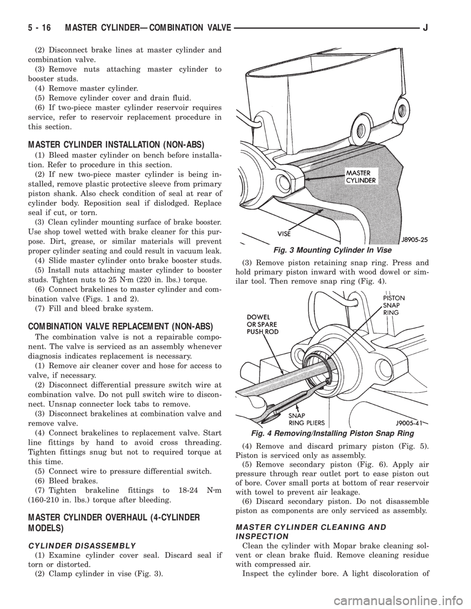
(2) Clamp cylinder in vise (Fig. 3).(3) Remove piston retaining snap ring. Press and
hold primary piston inward with wood dowel or sim-
ilar tool. Then remove snap ring (Fig. 4).
(4) Remove and discard primary piston (Fig. 5).
Piston is serviced only as assembly.
(5) Remove secondary piston (Fig. 6). Apply air
pressure through rear outlet port to ease piston out
of bore. Cover small ports at bottom of rear reservoir
with towel to prevent air leakage.
(6) Discard secondary piston. Do not disassemble
piston as components are only serviced as assembly.
MASTER CYLINDER CLEANING AND
INSPECTION
Clean the cylinder with Mopar brake cleaning sol-
vent or clean brake fluid. Remove cleaning residue
with compressed air.
Inspect the cylinder bore. A light discoloration of
Fig. 3 Mounting Cylinder In Vise
Fig. 4 Removing/Installing Piston Snap Ring
5 - 16 MASTER CYLINDERÐCOMBINATION VALVEJ