Page 131 of 1771
Oil Pum p
Overhau l
NOTE:
Use ne w O-ring s whe n reassembling .
Apply oi l t o th e O-ring s befor e installation .
Us e liqui d gasket , Par t No . 0871 8 - 000 1 o r 0871 8 - 0003 .
Th e rotor s mus t b e installe d in th e sam e direction .
Afte r reassembly , chec k tha t th e rotor s mov e withou t binding .
PUMP COVE R
PUMP HOUSINGInspection , pag e 8-1 2
Appl y liqui d gaske t
t o matin g surfac e o f
th e cylinde r bloc k
whe n installing .
6 x 1. 0 m m8 N- m (0. 8 kgf-m ,6 Ibf-ft )
OUTE R ROTO RInspection , pag e 8-1 2
INNE R ROTO RInspection , pag e 8-1 2
OIL SEA LInstallation , pag e 8-1 3Replace .
SPRING
SPRINGSEAT
RELIE F VALV EValve mus t slid e freel y
i n housin g bore .
Replac e i f scored .
O-RINGReplace .
COTTER PI NReplace .
O-RINGSReplace .
ProCarManuals.com
Page 132 of 1771

Oil Pum p
Removal/lnspection/lnstallatio n
1. Drai n th e engin e oi l an d th e differentia l oil .
2 . Tur n th e crankshaf t t o TD C (se e pag e 6-10 ).
3 . Remov e th e timin g bel t (se e pag e 6-6 ).
4 . Remov e th e oi l pa n (se e pag e 8-7 ).
5 . Remov e th e specia l bolts , the n remov e th e oi l pump .
O-RING SReplace .
DOWEL PI N
OIL PUM P
DOWE LPIN O-RING SReplace.
6. Remov e th e screw s fro m th e pum p housing , the n
separat e th e housin g an d cover .
7 . Chec k th e inner-to-oute r roto r radia l clearanc e o n th e
pum p rotor .
Inner Rotor-to-Oute r Roto r Radia l Clearanc e
Standar d (New) : 0.0 2 - 0.1 6 m m
(0.00 1 - 0.00 6 in )
Servic e Limit : 0.2 0 m m (0.00 8 in )
OUTE R ROTO RINNER ROTO R
— If th e inner-to-oute r roto r clearanc e exceed s th e
servic e
limit, replac e the inne r and oute r rotors .
8 . Chec k th e housing-to-roto r axia l clearanc e o n th e
pum p rotor .
Housing-to-Roto r Axia l Clearanc e
Standar d (New) : 0.0 2 - 0.0 7 m m
(0.00 1 - 0.00 3 in )
Servic e Limit : 0.1 2 m m (0.00 5 in )
ROTO RHOUSIN G
If th e housing-to-roto r axia l clearanc e exceed s
the servic e limit , replac e th e se t of inne r an d
oute r rotor s and/o r th e pum p housing .
ProCarManuals.com
Page 133 of 1771
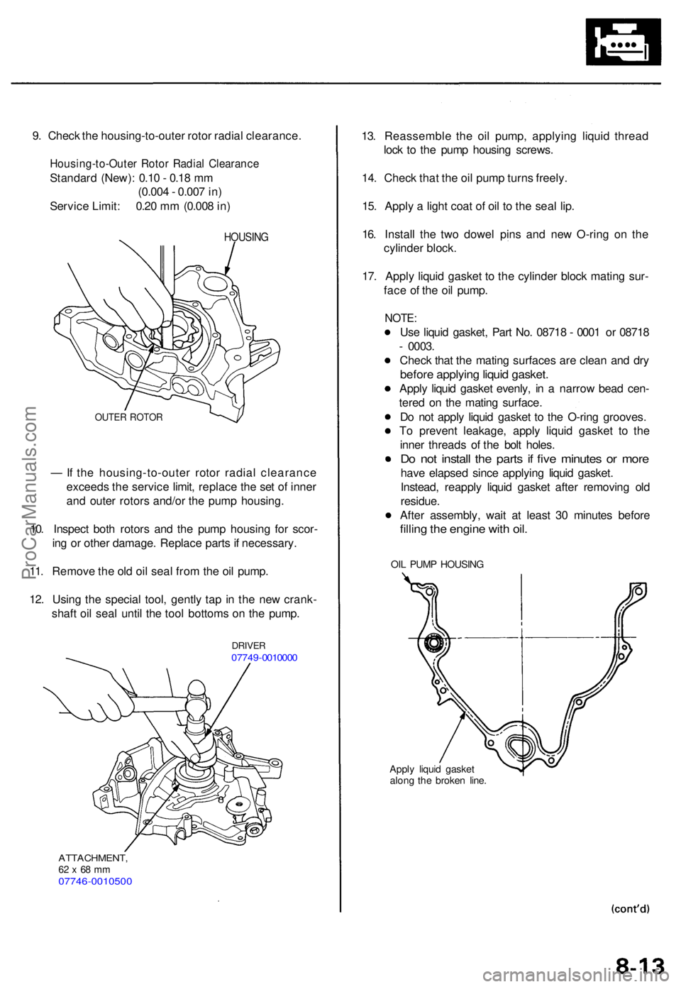
9. Chec k th e housing-to-oute r roto r radia l clearance .
Housing-to-Oute r Roto r Radia l Clearanc e
Standard (New) : 0.1 0 - 0.1 8 m m
(0.00 4 - 0.00 7 in )
Servic e Limit : 0.2 0 m m (0.00 8 in )
HOUSIN G
OUTER ROTO R
— If th e housing-to-oute r roto r radia l clearanc e
exceed s th e servic e limit , replac e th e se t o f inne r
an d oute r rotor s and/o r th e pum p housing .
10 . Inspec t bot h rotor s an d th e pum p housin g fo r scor -
in g o r othe r damage . Replac e part s if necessary .
11 . Remov e th e ol d oi l sea l fro m th e oi l pump .
12 . Usin g th e specia l tool , gentl y ta p i n th e ne w crank -
shaf t oi l sea l unti l th e too l bottom s o n th e pump .
DRIVE R07749-001000 0
ATTACHMENT ,62 x 68 m m07746-001050 0
13. Reassembl e th e oi l pump , applyin g liqui d threa d
loc k t o th e pum p housin g screws .
14 . Chec k tha t th e oi l pum p turn s freely .
15 . Appl y a ligh t coa t o f oi l t o th e sea l lip .
16 . Instal l th e tw o dowe l pin s an d ne w O-rin g o n th e
cylinde r block .
17 . Appl y liqui d gaske t t o th e cylinde r bloc k matin g sur -
fac e o f th e oi l pump .
NOTE:
Use liqui d gasket , Par t No . 0871 8 - 000 1 o r 0871 8
- 0003 .
Chec k tha t th e matin g surface s ar e clea n an d dr y
befor e applyin g liqui d gasket .
Apply liqui d gaske t evenly , i n a narro w bea d cen -
tere d o n th e matin g surface .
D o no t appl y liqui d gaske t t o th e O-rin g grooves .
T o preven t leakage , appl y liqui d gaske t t o th e
inne r thread s o f th e bol t holes .
Do no t instal l th e part s i f fiv e minute s o r mor e
have elapse d sinc e applyin g liqui d gasket .
Instead , reappl y liqui d gaske t afte r removin g ol d
residue .
Afte r assembly , wai t a t leas t 3 0 minute s befor e
filling th e engin e wit h oil .
OIL PUM P HOUSIN G
Apply liqui d gaske t
alon g th e broke n line .
ProCarManuals.com
Page 134 of 1771
Oil Pum p
10 x 1.2 5 mm44 N- m (4. 5 kgf-m ,
3 3 Ibf-ft )
DOWE L PI N O-RING S
Replace.
6 x 1. 0 m m12 N- m (1. 2 kgf-m ,
8. 7 Ibf-ft )
OILPUM P
O-RING SReplace .
DOWELPIN
8 x 1.2 5 mm22 N- m (2. 2 kgf-m ,
1 6 Ibf-ft )
19. Instal l th e oi l pa n (se e pag e 8-9 ).
20 . Instal l th e timin g bel t (se e pag e 6-8 ).
Removal/lnspection/lnstallatio n
(cont'd )
18. Instal l th e oi l pum p to th e cylinde r block .
ProCarManuals.com
Page 145 of 1771
Radiator
Cap Testing
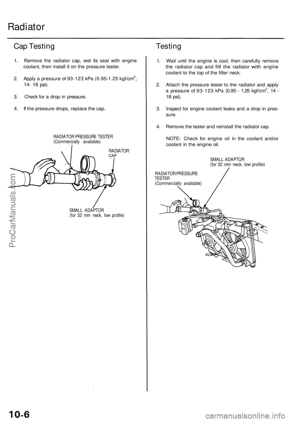
1. Remove the radiator cap, wet its seal with engine
coolant, then install it on the pressure tester.
2. Apply a pressure of 93-123 kPa (0.95-1.25 kgf/cm2,
14- 18
psi).
3. Check for a drop in pressure.
4. If the pressure drops, replace the cap.
RADIATOR PRESSURE TESTER
(Commercially available)
Testing
RADIATOR
CAP
SMALL ADAPTOR
(for 32 mm neck, low profile)
1. Wait until the engine is cool, then carefully remove
the
radiator
cap and
fill
the
radiator
with
engine
coolant to the top of the filler neck.
2. Attach the pressure tester to the radiator and apply
a pressure of 93-123 kPa (0.95 - 1.25 kgf/cm2, 14 -
18
psi).
3. Inspect for engine coolant leaks and a drop in pres-
sure.
4. Remove the tester and reinstall the radiator cap.
NOTE: Check for engine oil in the coolant and/or
coolant in the engine oil.
SMALL ADAPTOR
(for 32 mm neck, low profile)
RADIATOR PRESSURE
TESTER
(Commercially available)ProCarManuals.com
Page 201 of 1771
Powertrain Control Module (PCM)
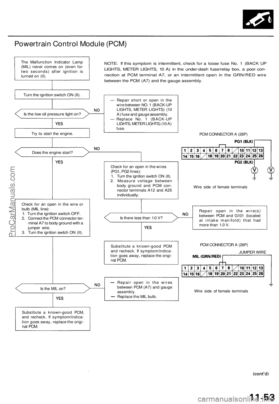
NOTE: If this symptom is intermittent, check for a loose fuse No. 1 (BACK UP
LIGHTS, METER LIGHTS, 10 A) in the under-dash fuse/relay box, a poor con-
nection at PCM terminal A7, or an intermittent open in the GRN/RED wire
between the PCM (A7) and the gauge assembly.
Is the low oil pressure light on?
Try to start the engine.
Does the engine start?
Check for an open in the wire or
bulb (MIL line):
1. Turn the ignition switch OFF.
2. Connect the PCM connector ter-
minal A7 to body ground with a
jumper wire.
3. Turn the ignition switch ON (II).
Is the MIL on?
Substitute a known-good PCM,
and recheck. If symptom/indica-
tion goes away, replace the origi-
nal
PCM.
— Repair short or open in the
wire between NO. 1 (BACK-UP
LIGHTS, METER LIGHTS) (10
A) fuse and gauge assembly.
— Replace No. 1 (BACK-UP
LIGHTS, METER LIGHTS) (10 A)
fuse.
PCM CONNECTOR A (26P)
Check for an open in the wires
(PG1, PG2 lines):
1. Turn the ignition switch ON (II).
2. Measure voltage between
body ground and PCM con-
nector terminals A12 and A25
individually.
Wire side of female terminals
Is there less than 1.0 V?
Repair open in the wire(s)
between PCM and G101 (located
at intake manifold) that had
more than 1.0 V.
PCM CONNECTOR A (26P)
JUMPER WIRE
Wire side of female terminals
Repair open in the wires
between PCM (A7) and gauge
assembly.
Replace the MIL bulb.
Substitute a known-good PCM
and recheck. If symptom/indica-
tion goes away, replace the origi-
nal
PCM.
Turn the ignition switch ON (II).
The Malfunction Indicator Lamp
(MIL) never comes on (even for
two seconds) after ignition is
turned on (II).ProCarManuals.com
Page 226 of 1771
Fuel Supply System
Fuel Injectors (cont'd)
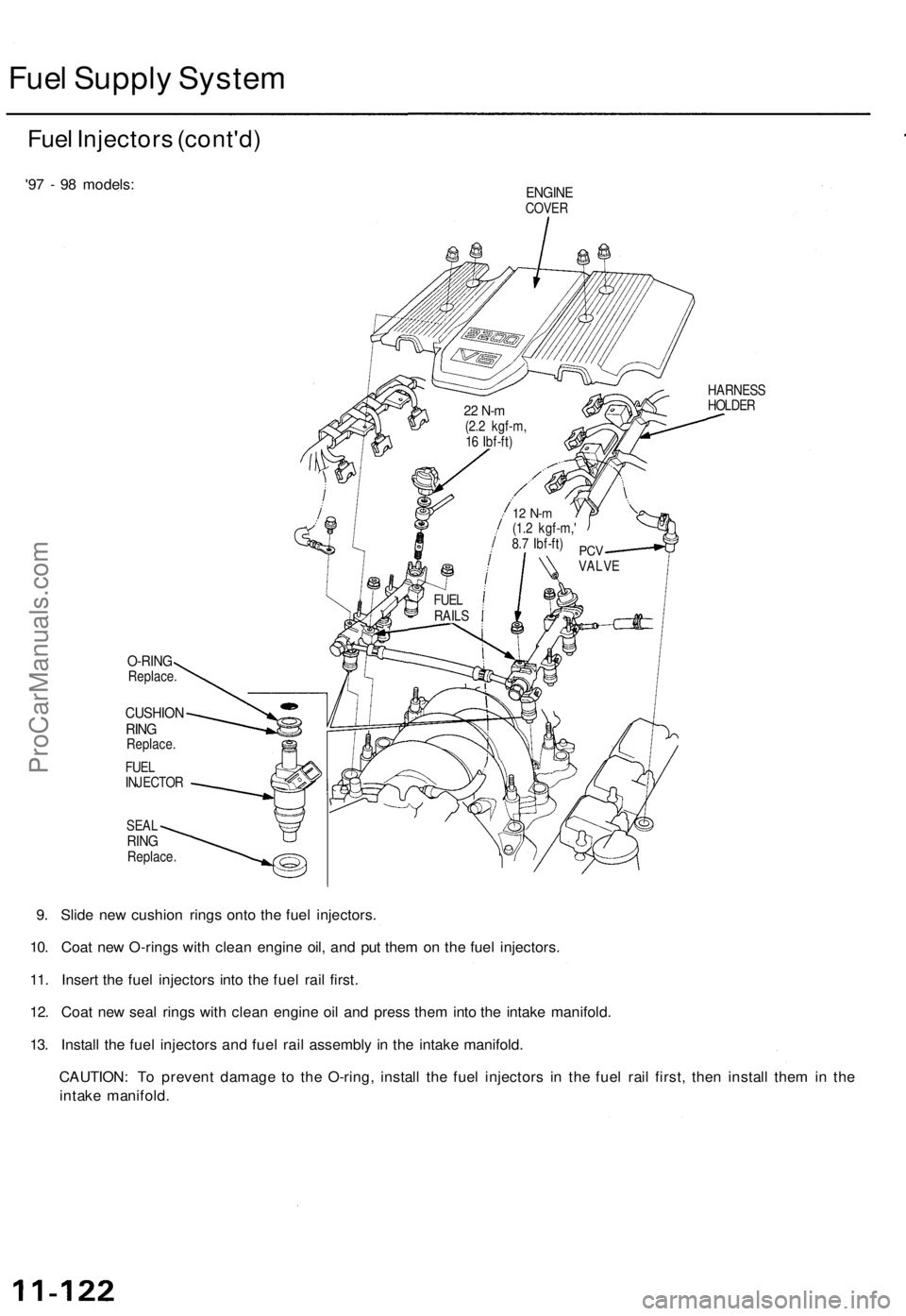
'97 - 98 models:
ENGINE
COVER
HARNESS
HOLDER
O-RING
Replace.
CUSHION
RING
Replace.
FUEL
INJECTOR
SEAL
RING
Replace.
9. Slide new cushion rings onto the fuel injectors.
10. Coat new O-rings with clean engine oil, and put them on the fuel injectors.
11. Insert the fuel injectors into the fuel rail first.
12. Coat new seal rings with clean engine oil and press them into the intake manifold.
13. Install the fuel injectors and fuel rail assembly in the intake manifold.
CAUTION: To prevent damage to the O-ring, install the fuel injectors in the fuel rail first, then install them in the
intake manifold.
22 N-m
(2.2 kgf-m,
16 Ibf-ft)
PCV
VALVE
FUEL
RAILS
12 N-m
(1.2 kgf-m,'
8.7 Ibf-ft)ProCarManuals.com
Page 294 of 1771
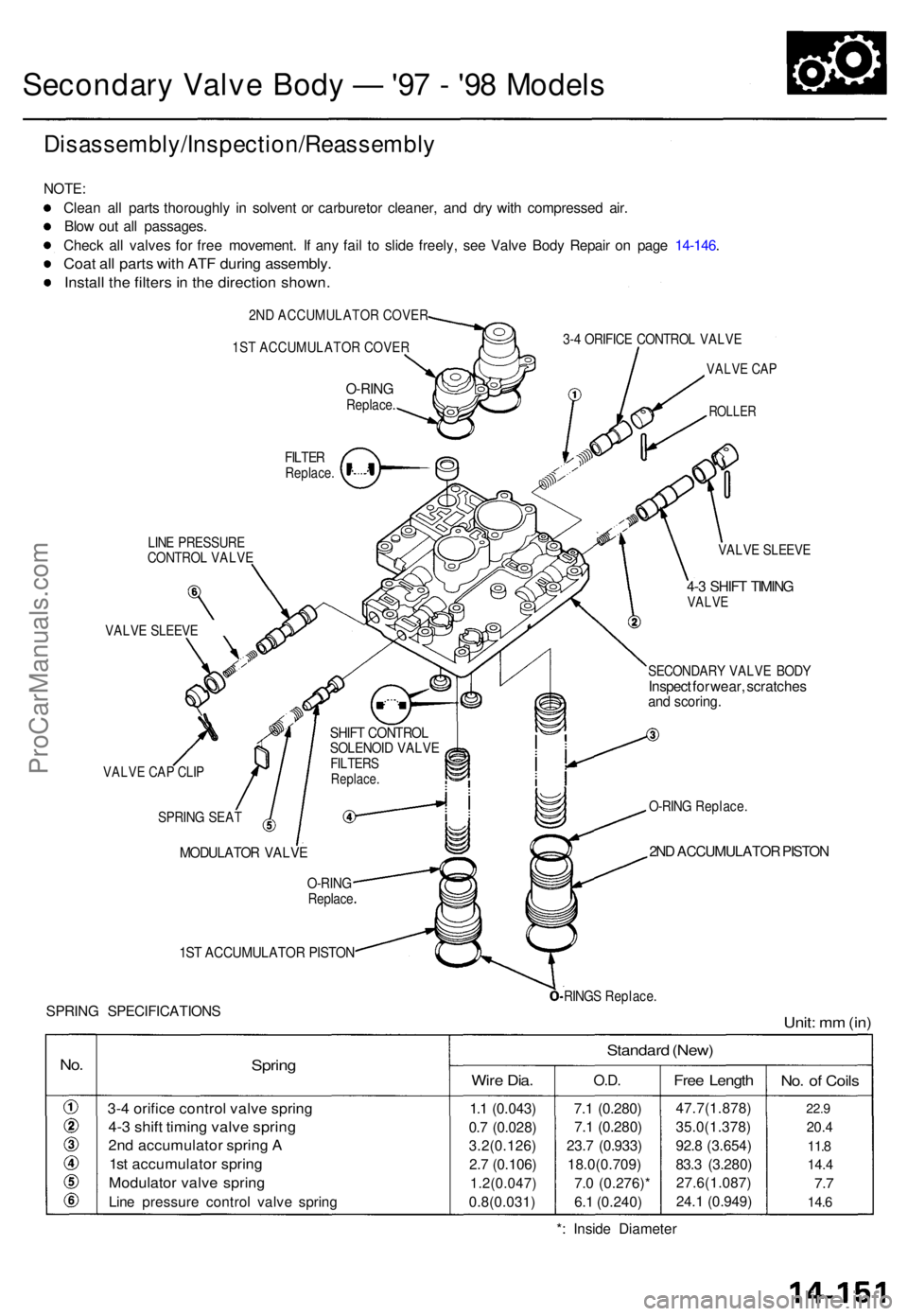
Secondary Valv e Bod y — '97 - '9 8 Model s
Disassembly/Inspection/Reassembl y
NOTE:
Clea n al l part s thoroughl y i n solven t o r carbureto r cleaner , an d dr y wit h compresse d air .
Blo w ou t al l passages .
Chec k al l valve s fo r fre e movement . I f an y fai l t o slid e freely , se e Valv e Bod y Repai r o n pag e 14-146 .
Coat al l part s wit h AT F durin g assembly .
Install th e filter s in th e directio n shown .
2ND ACCUMULATOR COVER
1ST ACCUMULATOR COVER
O-RIN GReplace .
3-4 ORIFIC E CONTRO L VALV E
VALVE CA P
ROLLE R
LINE PRESSUR ECONTROL VALV E
VALVE SLEEV E
VALVE CA P CLI P
SHIF T CONTRO LSOLENOID VALV EFILTER SReplace .
VALVE SLEEV E
4-3 SHIF T TIMIN GVALV E
SECONDAR Y VALV E BOD YInspec t fo r wear , scratche sand scoring .
SPRING SEA T
MODULATO R VALV E
O-RING Replace .
2ND ACCUMULATO R PISTO N
1ST ACCUMULATO R PISTO N
SPRING SPECIFICATION SRINGS Replace .
Unit: m m (in )
No.Sprin g
3-4 orific e contro l valv e sprin g
4-3 shif t timin g valv e sprin g
2nd accumulato r sprin g A
1s t accumulato r sprin g
Modulato r valv e sprin g
Line pressur e contro l valv e sprin g
Standar d (New )
Wire Dia .
1.1 (0.043 )
0. 7 (0.028 )
3.2(0.126 )
2. 7 (0.106 )
1.2(0.047 )
0.8(0.031)
O.D.
7.1 (0.280 )
7. 1 (0.280 )
23. 7 (0.933 )
18.0(0.709 )
7. 0 (0.276) *
6. 1 (0.240 )
Free Lengt h
47.7(1.878 )
35.0(1.378 )
92. 8 (3.654 )
83. 3 (3.280 )
27.6(1.087 )
24. 1 (0.949 )
No. o f Coil s
22.9
20. 4
11. 8
14. 4
7.7
14. 6
*: Insid e Diamete r
O-RINGReplac e
FILTERReplace .
ProCarManuals.com