Page 768 of 1771
Valves, Valve Springs and Valve Seals
Installation Sequence
NOTE: Exhaust and intake valve seals are NOT interchangeable.
VALVE SPRING
NOTE: Place the closely wound
end of the valve spring
toward the cylinder head.
VALVE KEEPERS
VALVE SPRING
RETAINER
EXHAUST VALVE SEAL
(BLACK SPRING)
Replace.
INTAKE VALVE SEAL
(WHITE SPRING)
Replace.
SPRING SEAT
NOTE: Install the valve spring seats
before installing the valve seals.
VALVE GUIDE SEAL INSTALLER
KD - 2899
(Commercially available)
NOTE: Use small I.D.
end of tool.
VALVE SEAL
Replace.ProCarManuals.com
Page 809 of 1771

Oil Filte r
Replacemen t (cont'd )
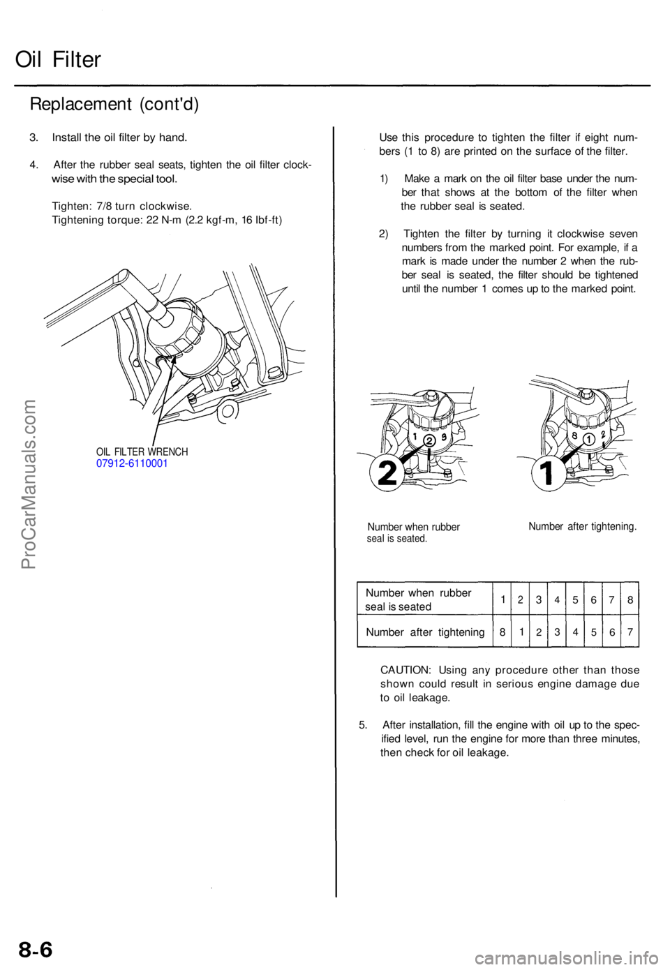
3. Instal l th e oi l filte r b y hand .
4. Afte r th e rubbe r sea l seats , tighte n th e oi l filte r clock -
wise wit h th e specia l tool .
Tighten : 7/ 8 tur n clockwise .
Tightenin g torque : 2 2 N- m (2. 2 kgf-m , 1 6 Ibf-ft )
OIL FILTE R WRENC H07912-611000 1
Use thi s procedur e t o tighte n th e filte r i f eigh t num -
ber s ( 1 t o 8 ) ar e printe d o n th e surfac e o f th e filter .
1 ) Mak e a mar k o n th e oi l filte r bas e unde r th e num -
be r tha t show s a t th e botto m o f th e filte r whe n
th e rubber seal i s seated .
2 ) Tighte n th e filte r b y turnin g i t clockwis e seve n
number s fro m th e marke d point . Fo r example , i f a
mar k i s mad e unde r th e numbe r 2 whe n th e rub -
be r sea l i s seated , th e filte r shoul d b e tightene d
unti l th e numbe r 1 come s u p to th e marke d point .
Numbe r whe n rubbe rseal i s seated .Number afte r tightening .
Number whe n rubbe r
sea l i s seate d
Numbe r afte r tightenin g1
8
2
1
3
2
4
3
5
4
6
5
7
6
8
7
CAUTION : Usin g an y procedur e othe r tha n thos e
show n coul d resul t i n seriou s engin e damag e du e
t o oi l leakage .
5 . Afte r installation , fil l th e engin e wit h oi l u p to th e spec -
ifie d level , ru n th e engin e fo r mor e tha n thre e minutes ,
the n chec k fo r oi l leakage .
ProCarManuals.com
Page 1399 of 1771

Moonroof
Motor, Drai n Tub e an d Fram e Replacemen t
CAUTION:
Wea r glove s t o remov e an d instal l th e frame .
B e carefu l no t t o damag e th e seats , dashboar d an d
othe r interio r trim .
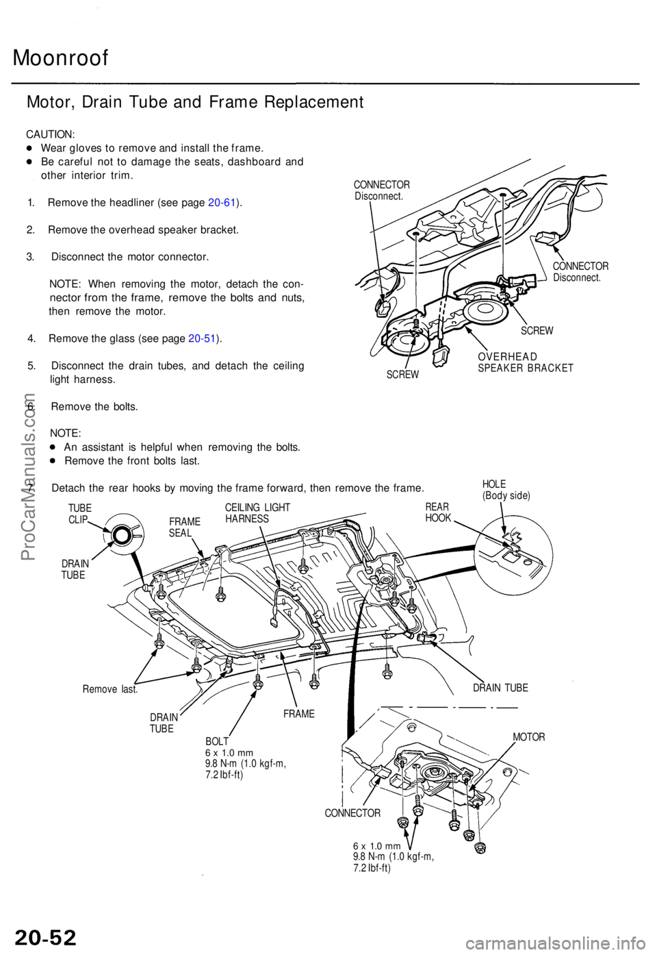
1 . Remov e th e headline r (se e pag e 20-61 ).
2 . Remov e th e overhea d speake r bracket .
3 . Disconnec t th e moto r connector .
NOTE : Whe n removin g th e motor , detac h th e con -
necto r fro m th e frame , remov e th e bolt s an d nuts ,
then remov e th e motor .
4 . Remov e th e glas s (se e pag e 20-51 ).
5 . Disconnec t th e drai n tubes , an d detac h th e ceilin g
ligh t harness .
6 . Remov e th e bolts .
CONNECTO R
Disconnect .
SCREW
CONNECTO R
Disconnect .
SCREW
OVERHEA DSPEAKER BRACKE T
NOTE:
A n assistan t i s helpfu l whe n removin g th e bolts .
Remov e th e fron t bolt s last .
7 . Detac h th e rea r hook s b y movin g th e fram e forward , the n remov e th e frame .
DRAIN
TUB E
HOL E(Bod y side )
Remov e last .
DRAI N
TUB E
BOL T6 x 1. 0 m m9.8 N- m (1. 0 kgf-m ,
7. 2 Ibf-ft )
6 x 1. 0 m m9.8 N- m (1. 0 kgf-m ,
7. 2 Ibf-ft ) MOTO
R
CONNECTO R
FRAM
E DRAI
N TUB E
REARHOO K
CEILIN
G LIGH THARNES SFRAMESEAL
TUBECLIP
ProCarManuals.com
Page 1415 of 1771

Center Console
Replacement
CAUTION: When prying with a flat tip screwdriver, wrap
it with protective tape to prevent damage.
NOTE: Take care not to scratch the center console, front
seat and related parts.
Center console/Center console panel removal:
1. Slide the front seats backward fully.
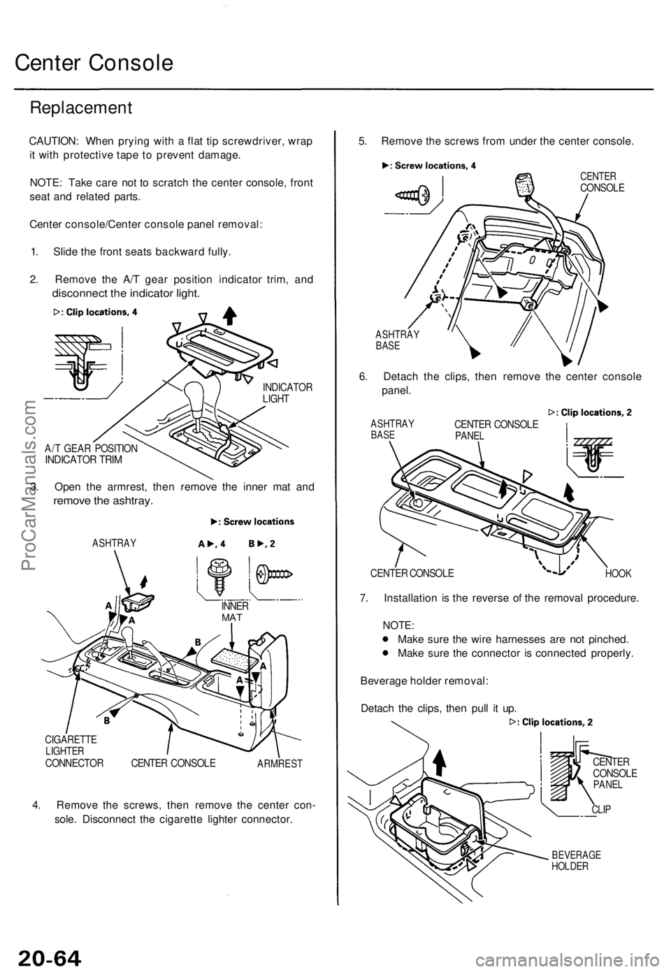
2. Remove the A/T gear position indicator trim, and
disconnect the indicator light.
INDICATOR
LIGHT
A/T GEAR POSITION
INDICATOR TRIM
3. Open the armrest, then remove the inner mat and
remove the ashtray.
ASHTRAY
CIGARETTE
LIGHTER
CONNECTOR CENTER CONSOLE
ARMREST
4. Remove the screws, then remove the center con-
sole. Disconnect the cigarette lighter connector.
5. Remove the screws from under the center console.
CENTER
CONSOLE
ASHTRAY
BASE
6. Detach the clips, then remove the center console
panel.
ASHTRAY
BASE
CENTER CONSOLE
PANEL
7. Installation is the reverse of the removal procedure.
NOTE:
Make sure the wire harnesses are not pinched.
Make sure the connector is connected properly.
Beverage holder removal:
Detach the clips, then pull it up.
CENTER
CONSOLE
PANEL
CLIP
BEVERAGE
HOLDER
INNER
MAT
HOOK
CENTER CONSOLEProCarManuals.com
Page 1422 of 1771
Seats/Seat Belt s
Componen t Locatio n Inde x
REAR SEA T BEL TReplacement , pag e 20-9 0
Inspection , pag e 20-9 2
FRON T SEA T BEL T
Replacement , pag e 20-8 8Inspection , pag e 20-9 2 SHOULDE
R
ANCHO R ADJUSTE R
(se e pag e 20-88 ) REA
R SEA T BEL T BUCKLE /
CENTE R BEL T TONGU E
(se e pag e 20-91 )
FRON T SEAT S
Removal , pag e 20-7 1
Seat-bac k Replacement , pag e 20-7 2
Sea t Cushio n Replacement , pag e 20-7 4
Sea t Cove r Replacement , pag e 20-7 6
Sea t Track s (Manuall y adjustable )
Replacement , pag e 20-7 8
Seat Linkag e (Full y powe r adjustable )Index, pag e 20-7 9
REA R SEAT-BAC KRemoval, pag e 20-8 5
Sea t Cove r Replacement ,
pag e 20-8 7
REA R SEA T CUSHIO N
Removal , pag e 20-8 5
Sea t Cove r Replacement , pag e 20-8 6
FRON T SEA T
BEL T BUCKLE S
(se e pag e 20-89 )
ProCarManuals.com