Page 1479 of 1771
Mirror
Mirror Holde r Replacemen t
CAUTION: Wea r glove s t o remov e an d instal l th e mir -
ro r holder .
1 . Carefull y pr y ou t th e mirro r holde r wit h a fla t ti p
screwdrive r a s shown .
PIVOT
JOINT PI N
MIRRO R HOLDE R
SHO P TOWE L
2. Installatio n is th e revers e o f th e remova l procedure .
Mirror Viso r an d Mirro r Cove r
Replacemen t
1. Remov e th e mirro r holder .
2 . Pus h th e mirro r bas e forward , the n remov e th e
screws .
3. Detac h th e hook , the n remov e th e mirro r visor .
MIRRO RBASE
MIRRO RCOVER
MIRRO R
VISO R
4. Installatio n is th e revers e o f th e remova l procedure .
JOINTPIN
ProCarManuals.com
Page 1542 of 1771
Relay and Control Unit Locations
Dashboard (cont'd)
ABS FAIL-SAFE RELAY
('97-98 models)
ABS FRONT FAIL-SAFE RELAY
('95 - 96 models)
FOG LIGHT RELAY
BLOWER MOTOR
HIGH RELAY
ABS REAR
FAIL-SAFE RELAY
('95 - 96 models)
UNDER-DASH
RELAY BOX
LOW BEAM
CUT RELAY
(Canada)
POWER MIRROR
DEFOGGER RELAY
(Canada)
ECM
DAYTIME
RUNNING LIGHTS
CONTROL UNIT
(Canada)
BLOWER
MOTOR
RELAY
HORN RELAYProCarManuals.com
Page 1644 of 1771

Glove Bo x Ligh t Vanit
y Mirro r Light s
Test
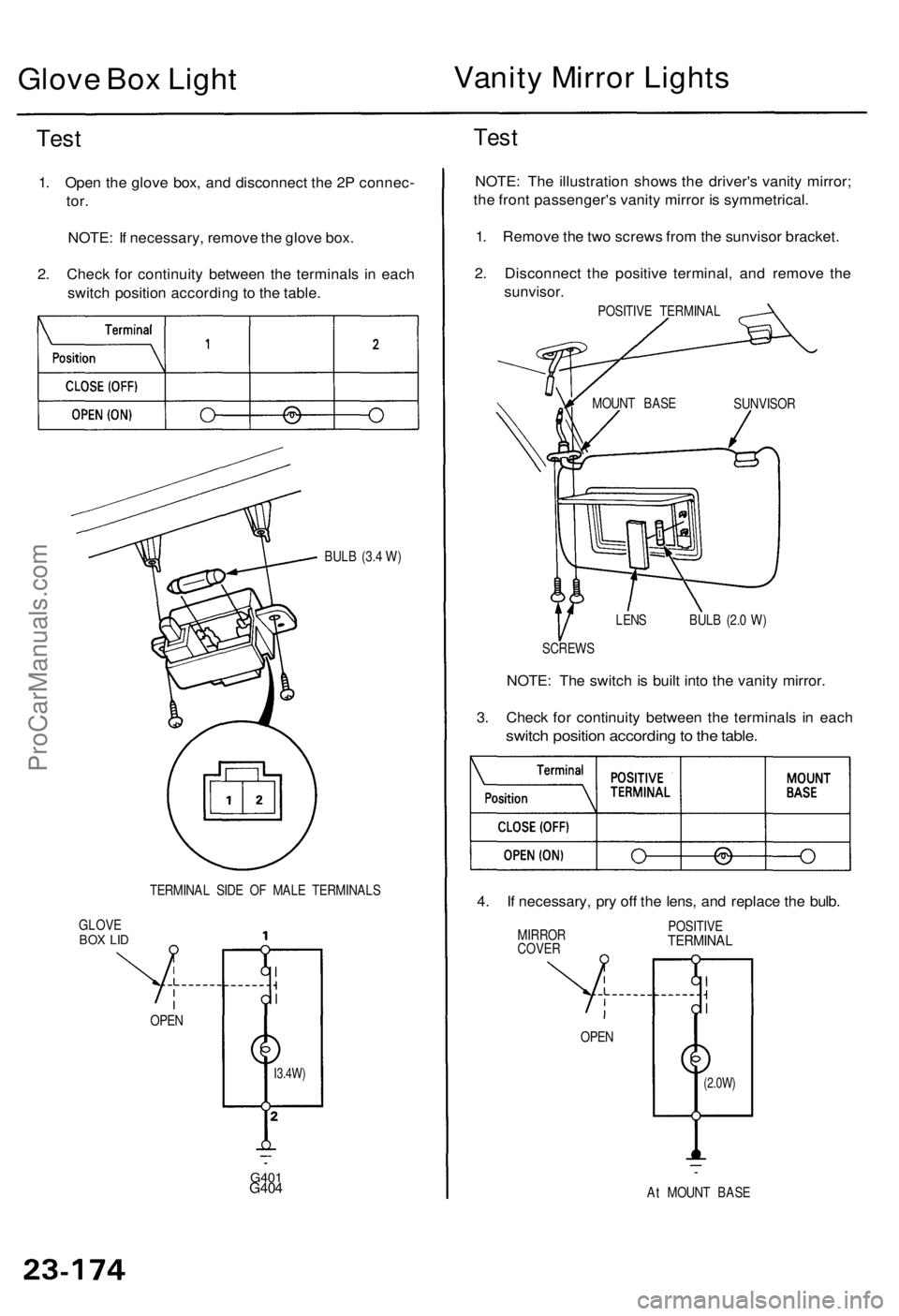
1. Ope n th e glov e box , an d disconnec t th e 2 P connec -
tor.
NOTE : I f necessary , remov e th e glov e box .
2 . Chec k fo r continuit y betwee n th e terminal s i n eac h
switc h positio n accordin g t o th e table .
BULB (3. 4 W )
TERMINA L SID E O F MAL E TERMINAL S
GLOV E
BOX LI D
G40 1G404
Test
NOTE : Th e illustratio n show s th e driver' s vanit y mirror ;
th e fron t passenger' s vanit y mirro r i s symmetrical .
1 . Remov e th e tw o screw s fro m th e sunviso r bracket .
2 . Disconnec t th e positiv e terminal , an d remov e th e
sunvisor .
POSITIVE TERMINA L
LEN S BUL B (2. 0 W )
SCREW S
NOTE: Th e switc h is buil t int o th e vanit y mirror .
3 . Chec k fo r continuit y betwee n th e terminal s i n eac h
switc h positio n accordin g to th e table .
4. I f necessary , pr y of f th e lens , an d replac e th e bulb .
MIRRO R
COVE R POSITIV
ETERMINA L
At MOUN T BAS E
OPE
N
OPEN
(2.0W )I3.4W)
SUNVISO R
MOUN
T BAS E
ProCarManuals.com
Page 1679 of 1771
Power Mirror s
Componen t Locatio n Inde x
POWE R MIRROR S
Functio n Test , pag e 23-22 2
Test , pag e 23-22 4
Replacement , sectio n 2 0
Actuato r Replacement , pag e 23-22 5
POWE R MIRRO R DEFOGGE R
RELA Y (Canad a an d '9 8 USA )
Test , pag e 23-6 2
POWER MIRRO R SWITC H
Test , pag e 23-22 3
Removal , pag e 23-22 2
UNDER-DAS
H
RELAY BO X
ProCarManuals.com
Page 1680 of 1771

Power Mirror s
Functio n Tes t
NOTE : B e carefu l no t t o damag e th e switc h an d th e
driver' s switc h panel .
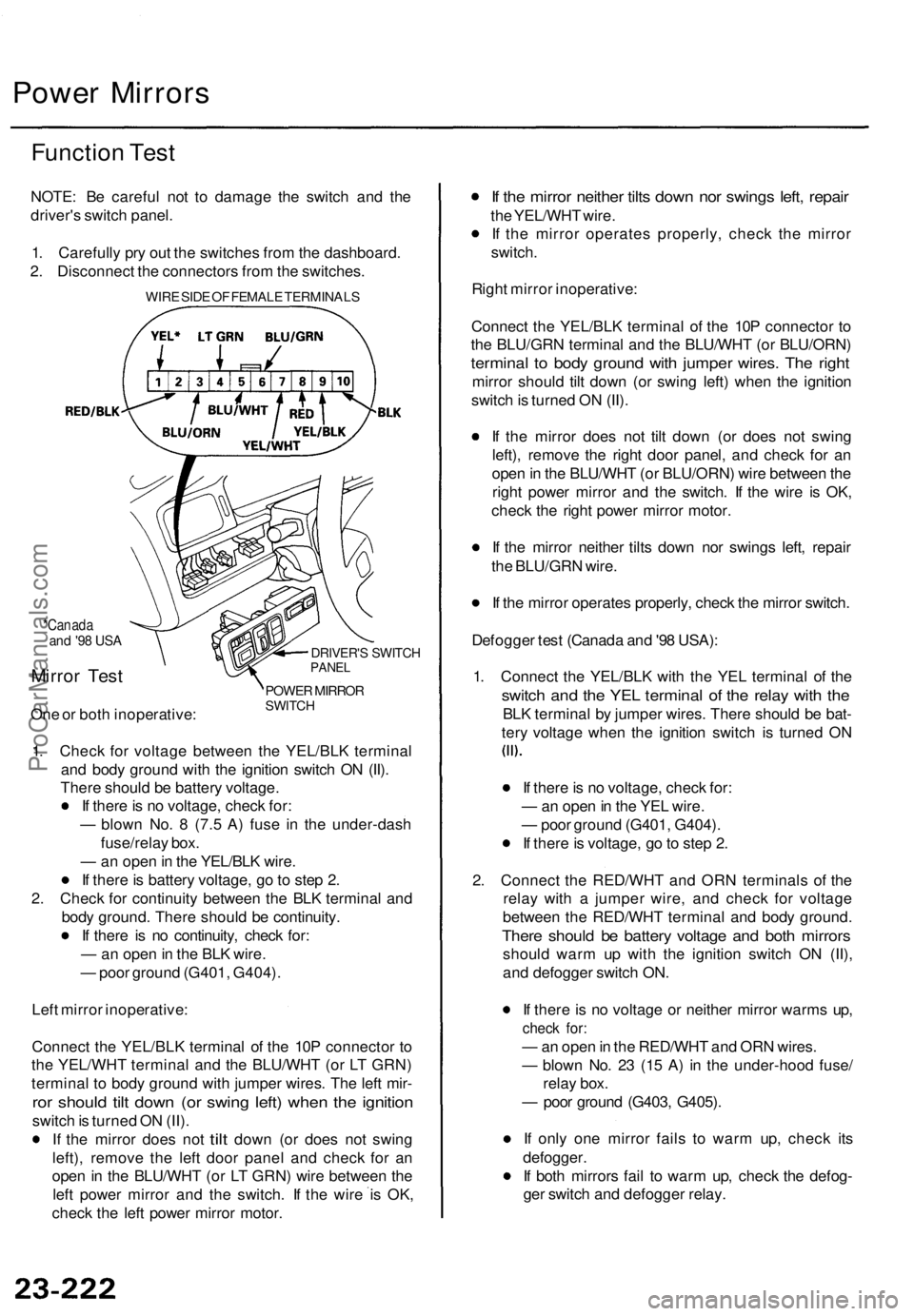
1 . Carefull y pr y ou t th e switche s fro m th e dashboard .
2 . Disconnec t th e connector s fro m th e switches .
WIRE SID E O F FEMAL E TERMINAL S
*Canadaand '9 8 US A
Mirro r Tes t
One o r bot h inoperative :
DRIVER'S SWITC HPANEL
POWE R MIRRO RSWITCH
1. Chec k fo r voltag e betwee n th e YEL/BL K termina l
an d bod y groun d wit h th e ignitio n switc h O N (II) .
Ther e shoul d b e batter y voltage .
I f ther e is n o voltage , chec k for :
— blow n No . 8 (7. 5 A ) fus e i n th e under-das h
fuse/rela y box .
— an ope n in th e YEL/BL K wire .
I f ther e is batter y voltage , g o to ste p 2 .
2 . Chec k fo r continuit y betwee n th e BL K termina l an d
bod y ground . Ther e shoul d b e continuity .
I f ther e i s n o continuity , chec k for :
— an ope n in th e BL K wire .
— poo r groun d (G401 , G404) .
Lef t mirro r inoperative :
Connec t th e YEL/BL K termina l o f th e 10 P connecto r t o
th e YEL/WH T termina l an d th e BLU/WH T (o r L T GRN )
termina l t o bod y groun d wit h jumpe r wires . Th e lef t mir -
ror shoul d til t dow n (o r swin g left ) whe n th e ignitio n
switch is turne d O N (II) .
I f th e mirro r doe s no t
tilt dow n (o r doe s no t swin g
left) , remov e th e lef t doo r pane l an d chec k fo r a n
ope n in th e BLU/WH T (o r L T GRN ) wir e betwee n th e
lef t powe r mirro r an d th e switch . I f th e wir e i s OK ,
chec k th e lef t powe r mirro r motor .
If th e mirro r neithe r tilt s dow n no r swing s left , repai r
the YEL/WH T wire .
I f th e mirro r operate s properly , chec k th e mirro r
switch .
Righ t mirro r inoperative :
Connec t th e YEL/BL K termina l o f th e 10 P connecto r t o
th e BLU/GR N termina l an d th e BLU/WH T (o r BLU/ORN )
terminal t o bod y groun d wit h jumpe r wires . Th e righ t
mirro r shoul d til t dow n (o r swin g left ) whe n th e ignitio n
switc h is turne d O N (II) .
I f th e mirro r doe s no t til t dow n (o r doe s no t swin g
left) , remov e th e righ t doo r panel , an d chec k fo r a n
ope n in th e BLU/WH T (o r BLU/ORN ) wir e betwee n th e
righ t powe r mirro r an d th e switch . I f th e wir e i s OK ,
chec k th e righ t powe r mirro r motor .
I f th e mirro r neithe r tilt s dow n no r swing s left , repai r
th e BLU/GR N wire .
I f th e mirro r operate s properly , chec k th e mirro r switch .
Defogge r tes t (Canad a an d '9 8 USA) :
1 . Connec t th e YEL/BL K wit h th e YE L termina l o f th e
switc h an d th e YE L termina l o f th e rela y wit h th e
BL K termina l b y jumpe r wires . Ther e shoul d b e bat -
ter y voltag e whe n th e ignitio n switc h i s turne d O N
I f ther e is n o voltage , chec k for :
— an ope n in th e YE L wire .
— poo r groun d (G401 , G404) .
I f ther e is voltage , g o to ste p 2 .
2 . Connec t th e RED/WH T an d OR N terminal s o f th e
rela y wit h a jumpe r wire , an d chec k fo r voltag e
betwee n th e RED/WH T termina l an d bod y ground .
There shoul d b e batter y voltag e an d bot h mirror s
should war m u p wit h th e ignitio n switc h O N (II) ,
an d defogge r switc h ON .
I f ther e is n o voltag e o r neithe r mirro r warm s up ,
chec k for :
— an ope n in th e RED/WH T an d OR N wires .
— blow n No . 2 3 (1 5 A ) i n th e under-hoo d fuse /
rela y box .
— poo r groun d (G403 , G405) .
I f onl y on e mirro r fail s t o war m up , chec k it s
defogger .
I f bot h mirror s fai l t o war m up , chec k th e defog -
ge r switc h an d defogge r relay .
ProCarManuals.com
Page 1682 of 1771
Power Mirror s
Power Mirro r Tes t
1. Remov e th e doo r pane l (se e sectio n 20 ), the n dis -
connec t th e 3 P connecto r an d 2 P connecto r (Canad a
an d '9 8 USA ) fro m th e powe r mirro r actuator .
POWERMIRRO R
TERMINAL SID E O F
MAL E TERMINAL S
2 P CONNECTO R
(Canad a an d
'98 USA )
3P CONNECTO R
WIR E SID E O F FEMAL E
TERMINAL S
2. Chec k actuato r operation by connectin g powe r an d
groun d accordin g t o th e table . 3
. Chec k fo r continuit y betwee n th e terminal s accord -
in g t o th e table .
Canad a an d '9 8 USA :
4. I f th e mirro r actuato r fail s t o operat e properly ,
replace it (se e page 23-225 ).
ProCarManuals.com
Page 1683 of 1771

Mirror Actuator Replacement
Removal:
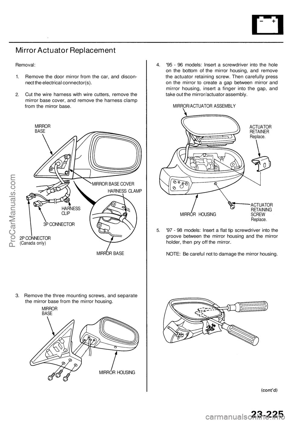
1.
2.
Remove the door mirror from the car, and discon-
nect the electrical connector(s).
Cut the wire harness with wire cutters, remove the
mirror base cover, and remove the harness clamp
from the mirror base.
MIRROR
BASE
2P CONNECTOR
(Canada only)
MIRROR BASE
3. Remove the three mounting screws, and separate
the mirror base from the mirror housing.
MIRROR
BASE
MIRROR HOUSING
4. '95 - 96 models: Insert a screwdriver into the hole
on the bottom of the mirror housing, and remove
the actuator retaining screw. Then carefully press
on the mirror to create a gap between mirror and
mirror housing, insert a finger into the gap, and
take out the mirror/actuator assembly.
MIRROR/ACTUATOR ASSEMBLY
ACTUATOR
RETAINER
Replace.
MIRROR HOUSING
ACTUATOR
RETAINING
SCREW
Replace.
5.
'97 - 98 models: Insert a flat tip screwdriver into the
groove between the mirror housing and the mirror
holder, then pry off the mirror.
NOTE: Be careful not to damage the mirror housing.
MIRROR BASE COVER
HARNESS CLAMP
HARNESS
CLIP
3P CONNECTORProCarManuals.com
Page 1684 of 1771

Power Mirrors
Mirror Actuator Replacement (cont'd)
6.
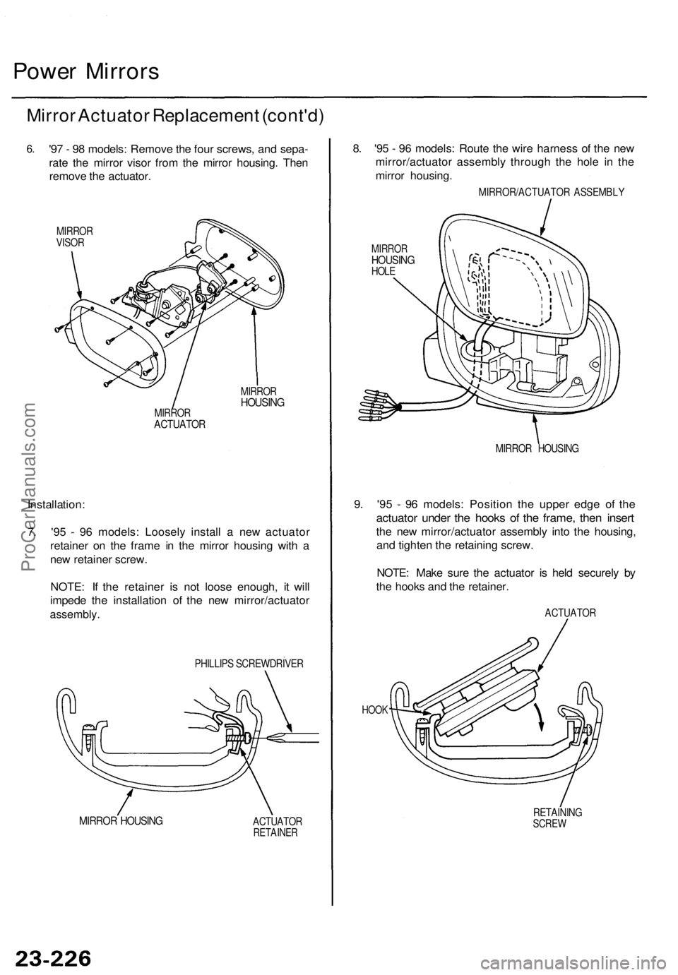
'97 - 98 models: Remove the four screws, and sepa-
rate the mirror visor from the mirror housing. Then
remove the actuator.
MIRROR
VISOR
MIRROR
HOUSING
MIRROR
ACTUATOR
Installation:
7. '95 - 96 models: Loosely install a new actuator
retainer on the frame in the mirror housing with a
new retainer screw.
NOTE: If the retainer is not loose enough, it will
impede the installation of the new mirror/actuator
assembly.
PHILLIPS SCREWDRIVER
MIRROR HOUSING
ACTUATOR
RETAINER
8. '95 - 96 models: Route the wire harness of the new
mirror/actuator assembly through the hole in the
mirror housing.
MIRROR/ACTUATOR ASSEMBLY
MIRROR
HOUSING
HOLE
MIRROR HOUSING
9. '95 - 96 models: Position the upper edge of the
actuator under the hooks of the frame, then insert
the new mirror/actuator assembly into the housing,
and tighten the retaining screw.
NOTE: Make sure the actuator is held securely by
the hooks and the retainer.
ACTUATOR
HOOK
RETAINING
SCREWProCarManuals.com