Page 1418 of 1771
Glove box removal:
1. Open the glove box.
2. Detach the damper clip. Remove the bolts while hold-
ing the glove box, then remove it.
5 x 0.8 mm
9 N-m (0.9 kgf-m,
7 Ibf-ft)
DAMPER CLIP
DAMPER
GLOVE BOX
SIDE AIR VENT
Open the glove box, then push the
clips from the glove box opening by
hand, and pull it out.
Bolt locations, 2
3. Installation is the reverse of the removal procedure.
Side air vent (Front passenger's)/Side defogger trim
removal:
Clip locations
SIDE DEFOGGER TRIM
Carefully pry it at the rear edge,
then remove it.
SHOP
TOWEL
HOOK CLIP
HOOK
CLIP
Push here.ProCarManuals.com
Page 1436 of 1771

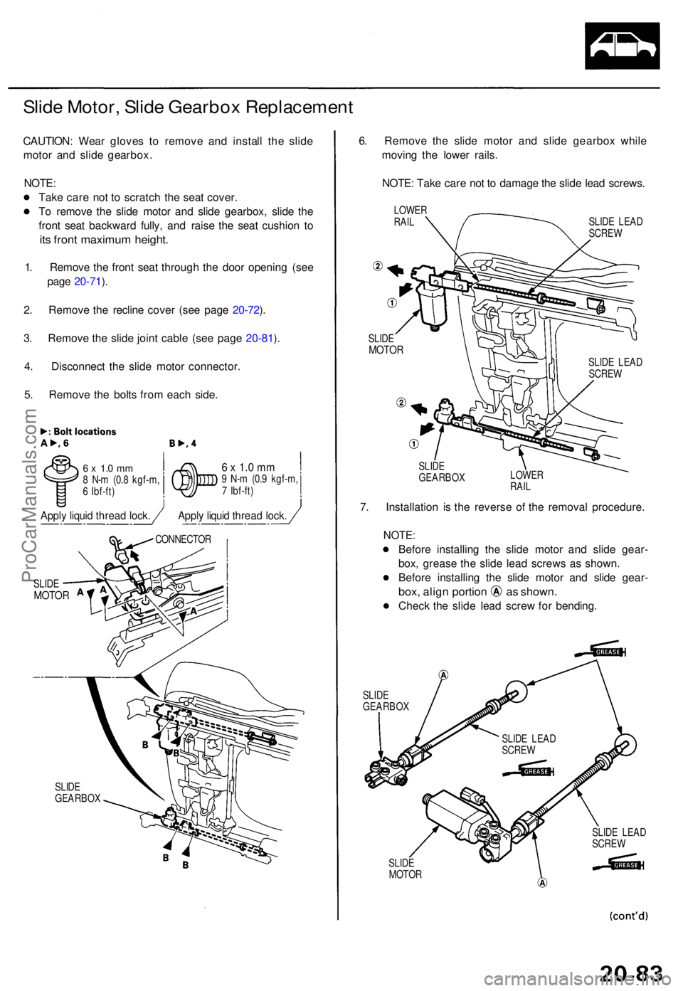
Slide Motor , Slid e Gearbo x Replacemen t
CAUTION: Wea r glove s t o remov e an d instal l th e slid e
moto r an d slid e gearbox .
NOTE :
Tak e car e no t t o scratc h th e sea t cover .
T o remov e th e slid e moto r an d slid e gearbox , slid e th e
fron t sea t backwar d fully , an d rais e th e sea t cushio n t o
its fron t maximu m height .
1. Remov e th e fron t sea t throug h th e doo r openin g (se e
pag e 20-71 ).
2 . Remov e th e reclin e cove r (se e pag e 20-72 ).
3 . Remov e th e slid e join t cabl e (se e pag e 20-81 ).
4 . Disconnec t th e slid e moto r connector .
5 . Remov e th e bolt s fro m eac h side .
6 x 1. 0 m m8 N- m (0. 8 kgf-m ,
6 Ibf-ft )6 x 1. 0 m m9 N- m (0. 9 kgf-m ,
7 Ibf-ft )
SLID E
GEARBO X
6. Remov e th e slid e moto r an d slid e gearbo x whil e
movin g th e lowe r rails .
NOTE : Tak e car e no t t o damag e th e slid e lea d screws .
LOWERRAILSLID E LEA D
SCRE W
SLID E
MOTO R
SLIDE
GEARBO X LOWE
R
RAIL
7. Installatio n i s th e revers e o f th e remova l procedure .
NOTE:
Before installin g th e slid e moto r an d slid e gear -
box , greas e th e slid e lea d screw s a s shown .
Befor e installin g th e slid e moto r an d slid e gear -
box, alig n portio n a s shown .
Check th e slid e lea d scre w fo r bending .
SLIDEGEARBO X
SLIDE
MOTO R SLID
E LEA D
SCRE W
SLID E
MOTO R
CONNECTO R
SLIDE LEA D
SCRE W
SLIDE LEA D
SCRE W
Apply liqui d threa d lock .Apply liqui d threa d lock .
ProCarManuals.com
Page 1644 of 1771

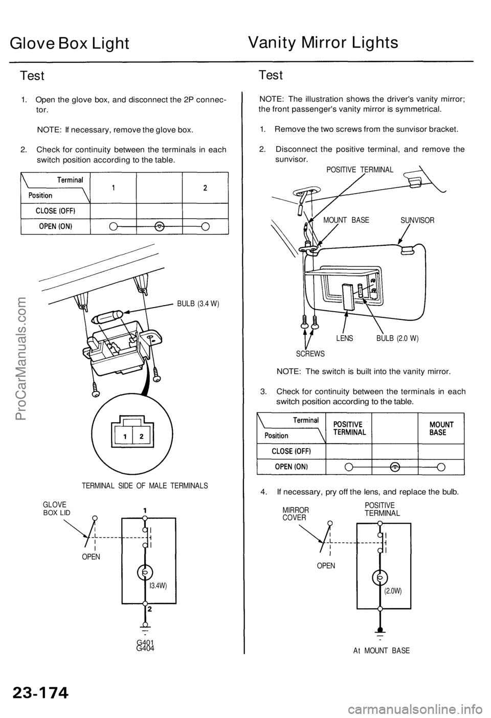
Glove Bo x Ligh t Vanit
y Mirro r Light s
Test
1. Ope n th e glov e box , an d disconnec t th e 2 P connec -
tor.
NOTE : I f necessary , remov e th e glov e box .
2 . Chec k fo r continuit y betwee n th e terminal s i n eac h
switc h positio n accordin g t o th e table .
BULB (3. 4 W )
TERMINA L SID E O F MAL E TERMINAL S
GLOV E
BOX LI D
G40 1G404
Test
NOTE : Th e illustratio n show s th e driver' s vanit y mirror ;
th e fron t passenger' s vanit y mirro r i s symmetrical .
1 . Remov e th e tw o screw s fro m th e sunviso r bracket .
2 . Disconnec t th e positiv e terminal , an d remov e th e
sunvisor .
POSITIVE TERMINA L
LEN S BUL B (2. 0 W )
SCREW S
NOTE: Th e switc h is buil t int o th e vanit y mirror .
3 . Chec k fo r continuit y betwee n th e terminal s i n eac h
switc h positio n accordin g to th e table .
4. I f necessary , pr y of f th e lens , an d replac e th e bulb .
MIRRO R
COVE R POSITIV
ETERMINA L
At MOUN T BAS E
OPE
N
OPEN
(2.0W )I3.4W)
SUNVISO R
MOUN
T BAS E
ProCarManuals.com
Page 1771 of 1771

SUPPLEMENTAL RESTRAINT SYSTEMThe Acura TL SRS includes a driver's airbag located in the steering wheel hub and a passenger's airbag located in the dashboard above
the glove box. Information necessary to safely service the SRS is included in this Service Manual. Items marked with an asterisk (*) on
the contents page include, or are located near, SRS components. Servicing, disassembling or replacing these items will require special
precautions and tools, and should therefore be done by an authorized Honda dealer.
WARNING
�To avoid rendering the SRS inoperative, which could lead to personal injury or death in the event of a severe frontal
collision, all SRS service work must be performed by an authorized Honda dealer.
�Improper service procedures, including incorrect removal and installation of the SRS, could lead to personal injury
caused by unintentional activation of the front airbags, seat belt tensioners, and side airbags ('99-01 models).
�Do not bump the SRS unit. Otherwise, the system may fail in a collision, or the airbags may deploy when the ignition
switch in ON (II).
�All SRS electrical wiring harnesses are covered with yellow insulation. Related components are located in the steering
column, front console, dashboard, dashboard lower panel, in the dashboard above the glove box. Do not use electrical
test equipment on these circuits.
NOTE: The original radio has a coded theft protection circuit. Be sure to get the customer's code number before
± disconnecting the battery.
± removing the No. 39 (10A) fuse from the under±hood fuse/relay box.
± removing the radio.
After service, reconnect power to the radio and turn it on. When the word ºCODEº is displayed, enter the customer's 5-digit code to restore
radio operation.
ProCarManuals.com