1994 JEEP CHEROKEE torque
[x] Cancel search: torquePage 184 of 1784
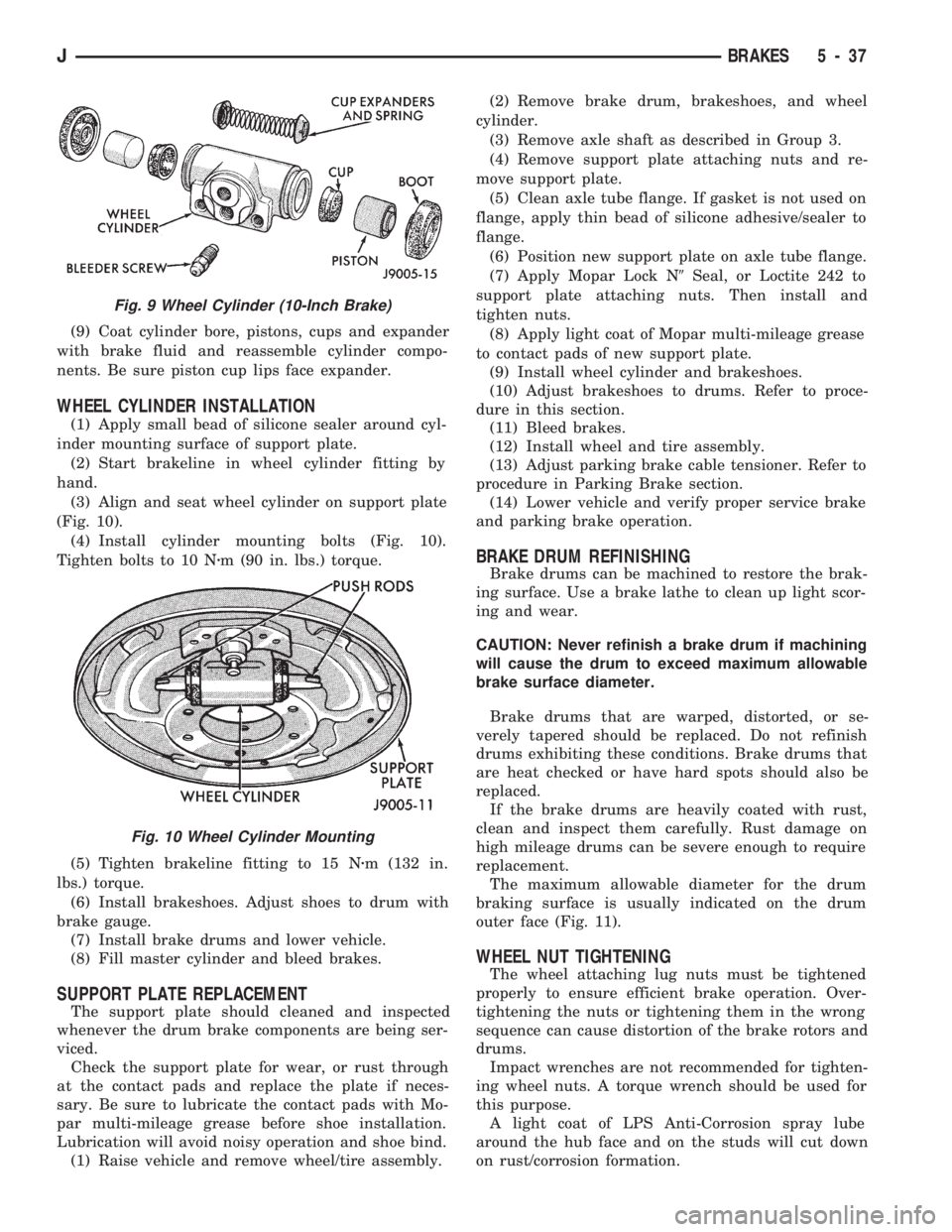
(9) Coat cylinder bore, pistons, cups and expander
with brake fluid and reassemble cylinder compo-
nents. Be sure piston cup lips face expander.
WHEEL CYLINDER INSTALLATION
(1) Apply small bead of silicone sealer around cyl-
inder mounting surface of support plate.
(2) Start brakeline in wheel cylinder fitting by
hand.
(3) Align and seat wheel cylinder on support plate
(Fig. 10).
(4) Install cylinder mounting bolts (Fig. 10).
Tighten bolts to 10 Nzm (90 in. lbs.) torque.
(5) Tighten brakeline fitting to 15 Nzm (132 in.
lbs.) torque.
(6) Install brakeshoes. Adjust shoes to drum with
brake gauge.
(7) Install brake drums and lower vehicle.
(8) Fill master cylinder and bleed brakes.
SUPPORT PLATE REPLACEMENT
The support plate should cleaned and inspected
whenever the drum brake components are being ser-
viced.
Check the support plate for wear, or rust through
at the contact pads and replace the plate if neces-
sary. Be sure to lubricate the contact pads with Mo-
par multi-mileage grease before shoe installation.
Lubrication will avoid noisy operation and shoe bind.
(1) Raise vehicle and remove wheel/tire assembly.(2) Remove brake drum, brakeshoes, and wheel
cylinder.
(3) Remove axle shaft as described in Group 3.
(4) Remove support plate attaching nuts and re-
move support plate.
(5) Clean axle tube flange. If gasket is not used on
flange, apply thin bead of silicone adhesive/sealer to
flange.
(6) Position new support plate on axle tube flange.
(7) Apply Mopar Lock N9Seal, or Loctite 242 to
support plate attaching nuts. Then install and
tighten nuts.
(8) Apply light coat of Mopar multi-mileage grease
to contact pads of new support plate.
(9) Install wheel cylinder and brakeshoes.
(10) Adjust brakeshoes to drums. Refer to proce-
dure in this section.
(11) Bleed brakes.
(12) Install wheel and tire assembly.
(13) Adjust parking brake cable tensioner. Refer to
procedure in Parking Brake section.
(14) Lower vehicle and verify proper service brake
and parking brake operation.
BRAKE DRUM REFINISHING
Brake drums can be machined to restore the brak-
ing surface. Use a brake lathe to clean up light scor-
ing and wear.
CAUTION: Never refinish a brake drum if machining
will cause the drum to exceed maximum allowable
brake surface diameter.
Brake drums that are warped, distorted, or se-
verely tapered should be replaced. Do not refinish
drums exhibiting these conditions. Brake drums that
are heat checked or have hard spots should also be
replaced.
If the brake drums are heavily coated with rust,
clean and inspect them carefully. Rust damage on
high mileage drums can be severe enough to require
replacement.
The maximum allowable diameter for the drum
braking surface is usually indicated on the drum
outer face (Fig. 11).
WHEEL NUT TIGHTENING
The wheel attaching lug nuts must be tightened
properly to ensure efficient brake operation. Over-
tightening the nuts or tightening them in the wrong
sequence can cause distortion of the brake rotors and
drums.
Impact wrenches are not recommended for tighten-
ing wheel nuts. A torque wrench should be used for
this purpose.
A light coat of LPS Anti-Corrosion spray lube
around the hub face and on the studs will cut down
on rust/corrosion formation.
Fig. 9 Wheel Cylinder (10-Inch Brake)
Fig. 10 Wheel Cylinder Mounting
JBRAKES 5 - 37
Page 185 of 1784
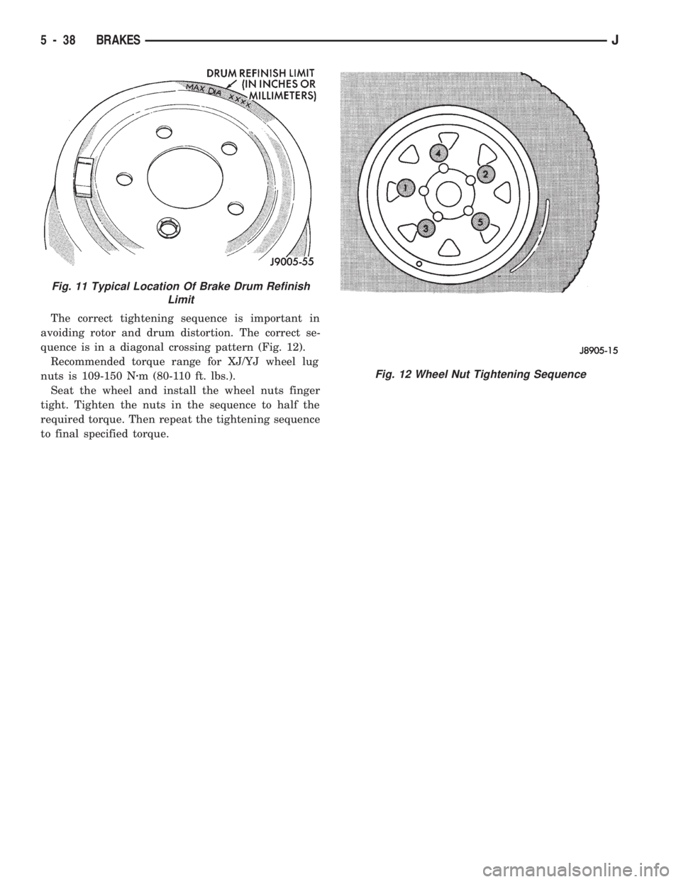
The correct tightening sequence is important in
avoiding rotor and drum distortion. The correct se-
quence is in a diagonal crossing pattern (Fig. 12).
Recommended torque range for XJ/YJ wheel lug
nuts is 109-150 Nzm (80-110 ft. lbs.).
Seat the wheel and install the wheel nuts finger
tight. Tighten the nuts in the sequence to half the
required torque. Then repeat the tightening sequence
to final specified torque.
Fig. 11 Typical Location Of Brake Drum Refinish
Limit
Fig. 12 Wheel Nut Tightening Sequence
5 - 38 BRAKESJ
Page 196 of 1784
Clean the reservoir and caps thoroughly before
checking level or adding fluid. Cap open lines and
hoses during service to prevent dirt entry.
Dirt or foreign material entering the ABS hydrau-
lic system through the reservoir opening will circu-
late within the system. The result will be poor brake
performance and possible component failure. Use
clean, fresh fluid only to top off, or refill the system.
WHEEL SENSOR AIR GAP ADJUSTMENT
Only rear sensor air gap is adjustable. The front
sensors are fixed and cannot be adjusted.
A rear sensor air gap adjustment is only
needed when reinstalling an original sensor. Re-
placement sensors have an air gap spacer at-
tached to the sensor pickup face. The spacer
establishes correct air gap when pressed against
the tone ring during installation. As the tone
ring rotates, it peels the spacer off the sensor to
create the required air gap.
Preferred rear sensor air gap is 1.1 mm (0.043 in.).
Acceptable air gap range is 0.92 to 1.275 mm (0.036
to 0.050 in.).
Front sensor air gap is not adjustable. The front
sensors are fixed in position and cannot be adjusted.
Front sensor air gap can only be checked. Air gap
should be 0.040 to 1.3 mm (0.0157 to 0.051 in.). If
front sensor air gap is incorrect, the sensor is either
loose, or damaged.
FRONT WHEEL SENSOR REMOVAL
(1) Raise vehicle and turn wheel outward for eas-
ier access to sensor.
(2) Remove sensor wire from mounting brackets.
(3) Clean sensor and surrounding area before removal.
(4) Remove bolt attaching sensor to steering
knuckle and remove sensor.
(5) Unseat grommet retaining sensor wire in wheel
house panel.
(6) In engine compartment, disconnect sensor wire con-
nector at harness plug. Then remove sensor and wire.
FRONT WHEEL SENSOR INSTALLATION
(1) Apply Mopar Lock N' Seal or Loctite 242 to
bolt that attaches sensor to steering knuckle. Use
new sensor bolt if original bolt is worn or damaged.
(2) Position sensor on steering knuckle. Seat sen-
sor locating tab in hole in knuckle and install sensor
attaching bolt finger tight.
(3) Tighten sensor bolt to 14 NIm (11 ft. lbs.) torque.
(4) Attach sensor wire to steering knuckle bracket
with grommets on sensor wire.
(5) Route sensor wire forward and behind shock
absorber. Then attach sensor wire to spring seat
bracket with grommets on sensor wire.
(6) Route sensor wire to outer sill bracket. Remove
all twists or kinks from wire.(7) Attach sensor wire to sill bracket with grom-
met. Be sure wire is free of twists and kinks.
(8) Verify sensor wire routing. Wire should loop
forward and above sill bracket. Loose end of wire
should be below sill bracket and towards brake hose.
(9) Seat sensor wire grommet in body panel and
clip wire to brake line at grommet location.
(10) Connect sensor wire to harness in engine com-
partment.
REAR WHEEL SENSOR REMOVAL
(1) On XJ models, if separate connectors are not
used to attach sensor harness to each sensor wire,
proceed as follows:
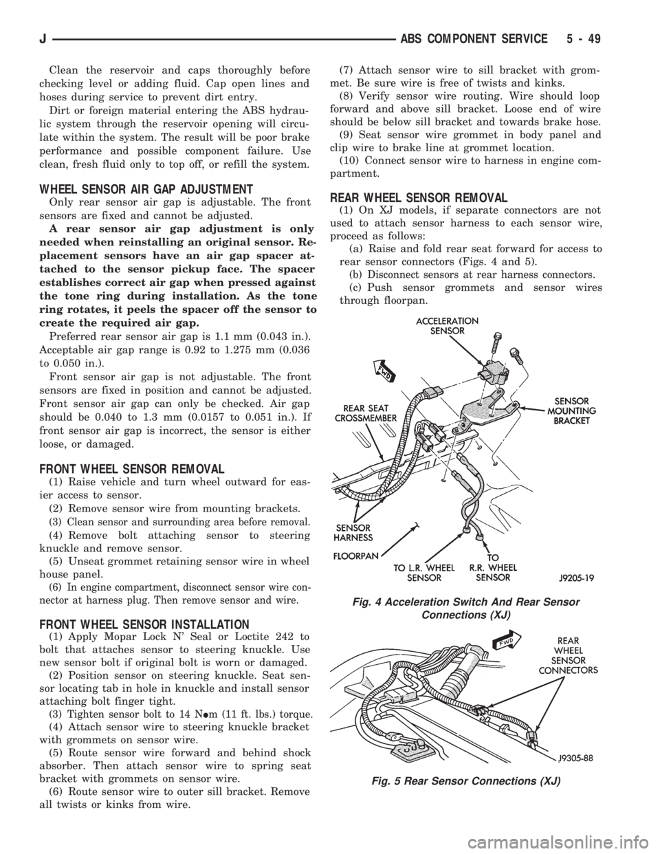
(a) Raise and fold rear seat forward for access to
rear sensor connectors (Figs. 4 and 5).
(b) Disconnect sensors at rear harness connectors.
(c) Push sensor grommets and sensor wires
through floorpan.
Fig. 4 Acceleration Switch And Rear Sensor
Connections (XJ)
Fig. 5 Rear Sensor Connections (XJ)
JABS COMPONENT SERVICE 5 - 49
Page 197 of 1784
(2) Raise vehicle.
(3) Disconnect sensor wires at rear axle connectors.
(4) Remove wheel and tire assembly.
(5) Remove brake drum.
(6) Remove clips securing sensor wires to brake
lines or rear axle and rear brake hose.
(7) Unseat sensor support plate grommet.
(8) Remove bolt attaching sensor to bracket and
remove sensor.
REAR WHEEL SENSOR INSTALLATION
(1) Insert sensor wire through support plate hole
and seat sensor grommet in support plate.
(2) Apply Mopar Lock N' Seal or Loctite 242 to
original sensor bolt. Use new bolt if original is worn
or damaged.
(3) Install sensor bolt finger tight only at this
time.
(4) Set sensor air gap as follows:
(a) Iforiginal sensoris being installed, remove
any remaining pieces of cardboard spacer from sen-
sor pickup face. Then adjust air gap to preferred
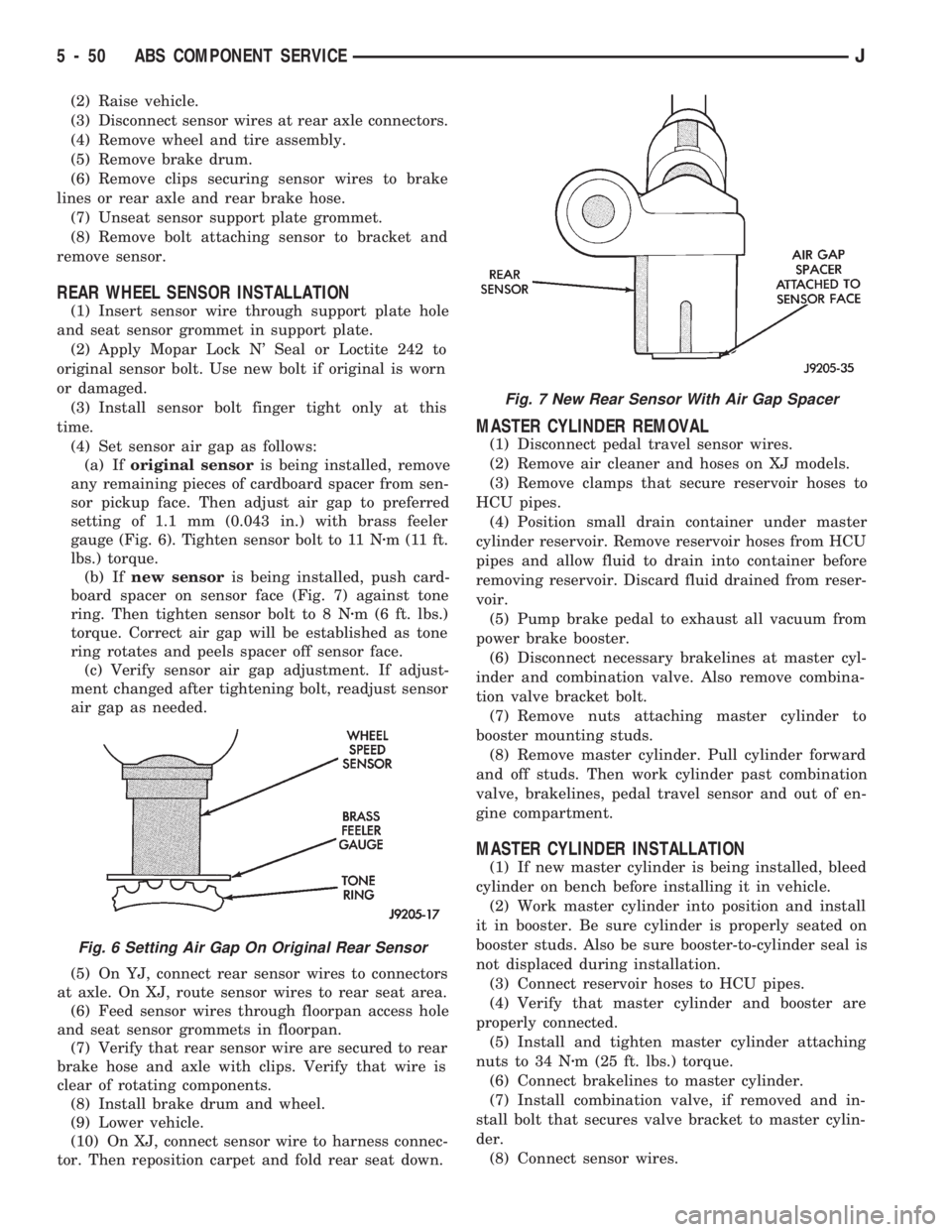
setting of 1.1 mm (0.043 in.) with brass feeler
gauge (Fig. 6). Tighten sensor bolt to 11 Nzm (11 ft.
lbs.) torque.
(b) Ifnew sensoris being installed, push card-
board spacer on sensor face (Fig. 7) against tone
ring. Then tighten sensor bolt to 8 Nzm (6 ft. lbs.)
torque. Correct air gap will be established as tone
ring rotates and peels spacer off sensor face.
(c) Verify sensor air gap adjustment. If adjust-
ment changed after tightening bolt, readjust sensor
air gap as needed.
(5) On YJ, connect rear sensor wires to connectors
at axle. On XJ, route sensor wires to rear seat area.
(6) Feed sensor wires through floorpan access hole
and seat sensor grommets in floorpan.
(7) Verify that rear sensor wire are secured to rear
brake hose and axle with clips. Verify that wire is
clear of rotating components.
(8) Install brake drum and wheel.
(9) Lower vehicle.
(10) On XJ, connect sensor wire to harness connec-
tor. Then reposition carpet and fold rear seat down.
MASTER CYLINDER REMOVAL
(1) Disconnect pedal travel sensor wires.
(2) Remove air cleaner and hoses on XJ models.
(3) Remove clamps that secure reservoir hoses to
HCU pipes.
(4) Position small drain container under master
cylinder reservoir. Remove reservoir hoses from HCU
pipes and allow fluid to drain into container before
removing reservoir. Discard fluid drained from reser-
voir.
(5) Pump brake pedal to exhaust all vacuum from
power brake booster.
(6) Disconnect necessary brakelines at master cyl-
inder and combination valve. Also remove combina-
tion valve bracket bolt.
(7) Remove nuts attaching master cylinder to
booster mounting studs.
(8) Remove master cylinder. Pull cylinder forward
and off studs. Then work cylinder past combination
valve, brakelines, pedal travel sensor and out of en-
gine compartment.
MASTER CYLINDER INSTALLATION
(1) If new master cylinder is being installed, bleed
cylinder on bench before installing it in vehicle.
(2) Work master cylinder into position and install
it in booster. Be sure cylinder is properly seated on
booster studs. Also be sure booster-to-cylinder seal is
not displaced during installation.
(3) Connect reservoir hoses to HCU pipes.
(4) Verify that master cylinder and booster are
properly connected.
(5) Install and tighten master cylinder attaching
nuts to 34 Nzm (25 ft. lbs.) torque.
(6) Connect brakelines to master cylinder.
(7) Install combination valve, if removed and in-
stall bolt that secures valve bracket to master cylin-
der.
(8) Connect sensor wires.
Fig. 6 Setting Air Gap On Original Rear Sensor
Fig. 7 New Rear Sensor With Air Gap Spacer
5 - 50 ABS COMPONENT SERVICEJ
Page 198 of 1784
(9) Fill reservoir and bleed brakes. Refer to proce-
dure in this section.
(10) Install air cleaner and hoses.
PEDAL TRAVEL SENSOR SERVICE
CAUTION: The pedal travel sensor and booster
must form a matched set. The cap on the sensor
plunger and booster shell are color coded for iden-
tification, and to ensure they are used as matched
sets. Be sure the color of the sensor cap and the
color dot on the booster shell are the same before
installation. Refer to the Sensor Replacement infor-
mation before installing a new or original sensor.
PEDAL TRAVEL SENSOR REMOVAL
(1) Disconnect wires at sensor.
(2) Pump brake pedal to exhaust all vacuum from
booster.
(3) Unseat sensor retaining ring.
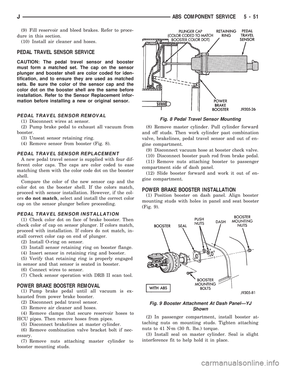
(4) Remove sensor from booster (Fig. 8).
PEDAL TRAVEL SENSOR REPLACEMENT
A new pedal travel sensor is supplied with four dif-
ferent color caps. The caps are color coded to ease
matching them with the color code dot on the booster
shell.
Compare the color of the new sensor cap and the
color dot on the booster shell. If the colors match,
proceed with sensor installation. However, if the col-
orsdo not match, select and install the correct color
cap on the sensor plunger before proceeding.
PEDAL TRAVEL SENSOR INSTALLATION
(1) Check color dot on face of brake booster. Then
check color of cap on sensor plunger. If colors match,
proceed with installation. If colors do not match, in-
stall correct color cap on end of plunger.
(2) Install O-ring on sensor.
(3) Install sensor retaining ring on booster flange.
(4) Insert sensor in retaining ring and booster.
(5) Verify that retaining ring is properly engaged
in sensor and that sensor is seated in booster.
(6) Connect wires to sensor.
(7) Check sensor operation with DRB II scan tool.
POWER BRAKE BOOSTER REMOVAL
(1) Pump brake pedal until all vacuum is ex-
hausted from power brake booster.
(2) Disconnect pedal travel sensor.
(3) Remove air cleaner and hoses.
(4) Remove clamps that secure reservoir hoses to
HCU pipes. Then remove hoses from pipes.
(5) Disconnect brakelines at master cylinder.
(6) Remove combination valve bracket bolt if nec-
essary.
(7) Remove nuts attaching master cylinder to
booster mounting studs.(8) Remove master cylinder. Pull cylinder forward
and off studs. Then work cylinder past combination
valve, brakelines, pedal travel sensor and out of en-
gine compartment.
(9) Disconnect vacuum hose at booster check valve.
(10) Disconnect booster push rod from brake pedal.
(11) Remove nuts attaching booster to passenger
compartment side of dash panel.
(12) Slide booster forward and work it out of en-
gine compartment.
POWER BRAKE BOOSTER INSTALLATION
(1) Position booster on dash panel. Align booster
mounting studs with holes in panel and seat booster
(Fig. 9).
(2) In passenger compartment, install booster at-
taching nuts on mounting studs. Tighten attaching
nuts to 41 Nzm (30 ft. lbs.) torque.
(3) Install seal on master cylinder. Seal is slight
interference fit to help hold it in place.
Fig. 8 Pedal Travel Sensor Mounting
Fig. 9 Booster Attachment At Dash PanelÐYJ
Shown
JABS COMPONENT SERVICE 5 - 51
Page 199 of 1784
CAUTION: The pedal travel sensor and booster
must form a matched set. The cap on the sensor
plunger and the color dot on the booster shell are
color coded for identification, and to ensure they
are used as matched sets. Be sure the color on the
sensor cap and booster shell are the same before
installation. Refer to the Sensor Replacement infor-
mation before installing a new or original sensor.
(4) If new pedal travel sensor is being installed in
original booster, compare color dot on booster shell with
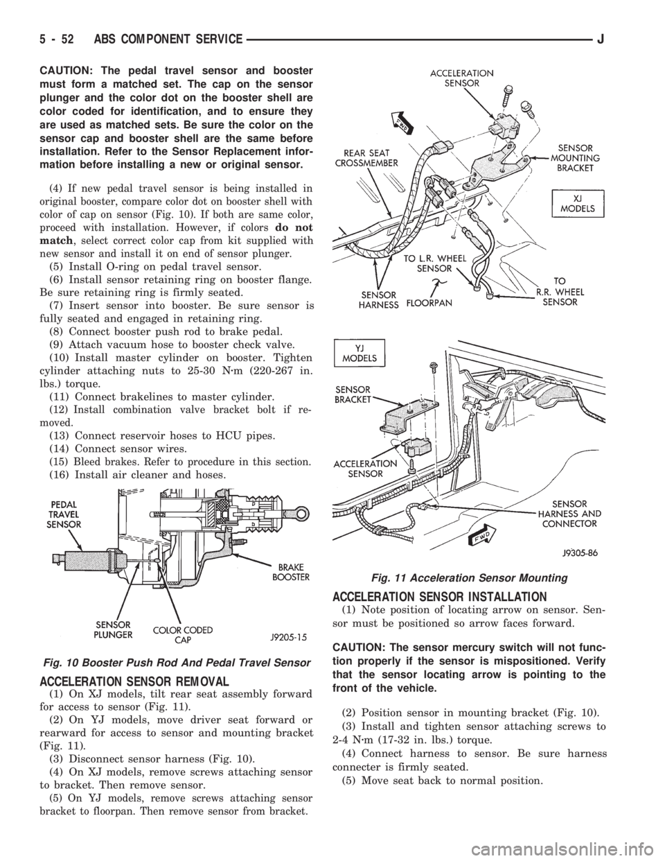
color of cap on sensor (Fig. 10). If both are same color,
proceed with installation. However, if colorsdo not
match, select correct color cap from kit supplied with
new sensor and install it on end of sensor plunger.
(5) Install O-ring on pedal travel sensor.
(6) Install sensor retaining ring on booster flange.
Be sure retaining ring is firmly seated.
(7) Insert sensor into booster. Be sure sensor is
fully seated and engaged in retaining ring.
(8) Connect booster push rod to brake pedal.
(9) Attach vacuum hose to booster check valve.
(10) Install master cylinder on booster. Tighten
cylinder attaching nuts to 25-30 Nzm (220-267 in.
lbs.) torque.
(11) Connect brakelines to master cylinder.
(12) Install combination valve bracket bolt if re-
moved.
(13) Connect reservoir hoses to HCU pipes.
(14) Connect sensor wires.
(15) Bleed brakes. Refer to procedure in this section.
(16) Install air cleaner and hoses.
ACCELERATION SENSOR REMOVAL
(1) On XJ models, tilt rear seat assembly forward
for access to sensor (Fig. 11).
(2) On YJ models, move driver seat forward or
rearward for access to sensor and mounting bracket
(Fig. 11).
(3) Disconnect sensor harness (Fig. 10).
(4) On XJ models, remove screws attaching sensor
to bracket. Then remove sensor.
(5) On YJ models, remove screws attaching sensor
bracket to floorpan. Then remove sensor from bracket.
ACCELERATION SENSOR INSTALLATION
(1) Note position of locating arrow on sensor. Sen-
sor must be positioned so arrow faces forward.
CAUTION: The sensor mercury switch will not func-
tion properly if the sensor is mispositioned. Verify
that the sensor locating arrow is pointing to the
front of the vehicle.
(2) Position sensor in mounting bracket (Fig. 10).
(3) Install and tighten sensor attaching screws to
2-4 Nzm (17-32 in. lbs.) torque.
(4) Connect harness to sensor. Be sure harness
connecter is firmly seated.
(5) Move seat back to normal position.
Fig. 10 Booster Push Rod And Pedal Travel Sensor
Fig. 11 Acceleration Sensor Mounting
5 - 52 ABS COMPONENT SERVICEJ
Page 200 of 1784
ECU REPLACEMENTÐXJ
ECU Removal
(1) Turn ignition key to Off position.
(2) Remove screws attaching ECU to mounting
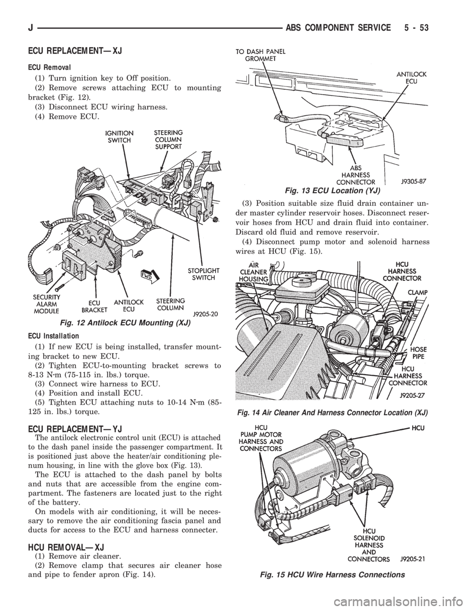
bracket (Fig. 12).
(3) Disconnect ECU wiring harness.
(4) Remove ECU.
ECU Installation
(1) If new ECU is being installed, transfer mount-
ing bracket to new ECU.
(2) Tighten ECU-to-mounting bracket screws to
8-13 Nzm (75-115 in. lbs.) torque.
(3) Connect wire harness to ECU.
(4) Position and install ECU.
(5) Tighten ECU attaching nuts to 10-14 Nzm (85-
125 in. lbs.) torque.
ECU REPLACEMENTÐYJ
The antilock electronic control unit (ECU) is attached
to the dash panel inside the passenger compartment. It
is positioned just above the heater/air conditioning ple-
num housing, in line with the glove box (Fig. 13).
The ECU is attached to the dash panel by bolts
and nuts that are accessible from the engine com-
partment. The fasteners are located just to the right
of the battery.
On models with air conditioning, it will be neces-
sary to remove the air conditioning fascia panel and
ducts for access to the ECU and harness connecter.
HCU REMOVALÐXJ
(1) Remove air cleaner.
(2) Remove clamp that secures air cleaner hose
and pipe to fender apron (Fig. 14).(3) Position suitable size fluid drain container un-
der master cylinder reservoir hoses. Disconnect reser-
voir hoses from HCU and drain fluid into container.
Discard old fluid and remove reservoir.
(4) Disconnect pump motor and solenoid harness
wires at HCU (Fig. 15).
Fig. 12 Antilock ECU Mounting (XJ)
Fig. 13 ECU Location (YJ)
Fig. 14 Air Cleaner And Harness Connector Location (XJ)
Fig. 15 HCU Wire Harness Connections
JABS COMPONENT SERVICE 5 - 53
Page 202 of 1784
(5) Fill and bleed brake system.
COMBINATION VALVE REPLACEMENTÐXJ
The combination valve is not a repairable compo-
nent. The valve is serviced as an assembly whenever
diagnosis indicates replacement is necessary.
(1) Remove air cleaner housing for access to valve,
if necessary.
(2) Remove bolt attached valve to master cylinder
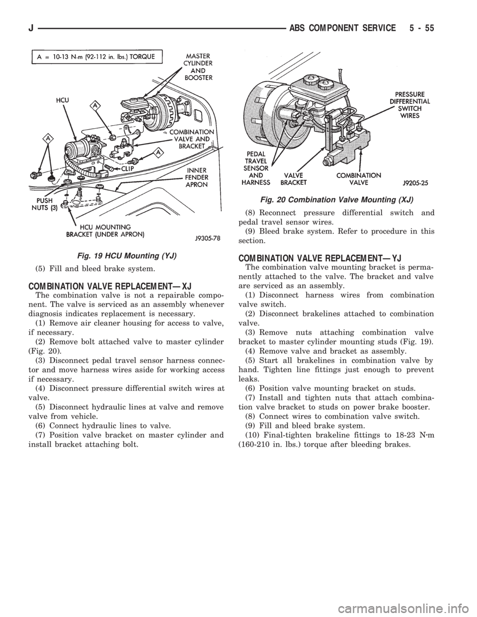
(Fig. 20).
(3) Disconnect pedal travel sensor harness connec-
tor and move harness wires aside for working access
if necessary.
(4) Disconnect pressure differential switch wires at
valve.
(5) Disconnect hydraulic lines at valve and remove
valve from vehicle.
(6) Connect hydraulic lines to valve.
(7) Position valve bracket on master cylinder and
install bracket attaching bolt.(8) Reconnect pressure differential switch and
pedal travel sensor wires.
(9) Bleed brake system. Refer to procedure in this
section.
COMBINATION VALVE REPLACEMENTÐYJ
The combination valve mounting bracket is perma-
nently attached to the valve. The bracket and valve
are serviced as an assembly.
(1) Disconnect harness wires from combination
valve switch.
(2) Disconnect brakelines attached to combination
valve.
(3) Remove nuts attaching combination valve
bracket to master cylinder mounting studs (Fig. 19).
(4) Remove valve and bracket as assembly.
(5) Start all brakelines in combination valve by
hand. Tighten line fittings just enough to prevent
leaks.
(6) Position valve mounting bracket on studs.
(7) Install and tighten nuts that attach combina-
tion valve bracket to studs on power brake booster.
(8) Connect wires to combination valve switch.
(9) Fill and bleed brake system.
(10) Final-tighten brakeline fittings to 18-23 Nzm
(160-210 in. lbs.) torque after bleeding brakes.
Fig. 19 HCU Mounting (YJ)
Fig. 20 Combination Valve Mounting (XJ)
JABS COMPONENT SERVICE 5 - 55