1994 JEEP CHEROKEE torque
[x] Cancel search: torquePage 68 of 1784
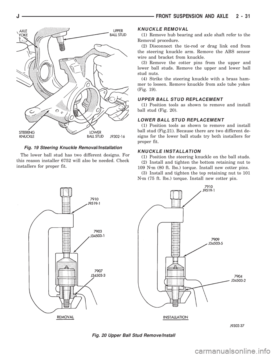
The lower ball stud has two different designs. For
this reason installer 6752 will also be needed. Check
installers for proper fit.
KNUCKLE REMOVAL
(1) Remove hub bearing and axle shaft refer to the
Removal procedure.
(2) Disconnect the tie-rod or drag link end from
the steering knuckle arm. Remove the ABS sensor
wire and bracket from knuckle.
(3) Remove the cotter pins from the upper and
lower ball studs. Remove the upper and lower ball
stud nuts.
(4) Strike the steering knuckle with a brass ham-
mer to loosen. Remove knuckle from axle tube yokes
(Fig. 19).
UPPER BALL STUD REPLACEMENT
(1) Position tools as shown to remove and install
ball stud (Fig. 20).
LOWER BALL STUD REPLACEMENT
(1) Position tools as shown to remove and install
ball stud (Fig.21). Because there are two different de-
signs for the lower ball studs try both installers for
proper fit.
KNUCKLE INSTALLATION
(1) Position the steering knuckle on the ball studs.
(2) Install and tighten the bottom retaining nut to
109 Nzm (80 ft. lbs.) torque. Install new cotter pins.
(3) Install and tighten the top retaining nut to 101
Nzm (75 ft. lbs.) torque. Install new cotter pin.
Fig. 19 Steering Knuckle Removal/Installation
Fig. 20 Upper Ball Stud Remove/Install
JFRONT SUSPENSION AND AXLE 2 - 31
Page 73 of 1784
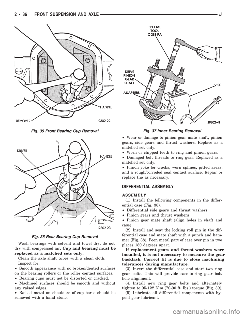
Wash bearings with solvent and towel dry, do not
dry with compressed air.Cup and bearing must be
replaced as a matched sets only.
Clean the axle shaft tubes with a clean cloth.
Inspect for;
²Smooth appearance with no broken/dented surfaces
on the bearing rollers or the roller contact surfaces.
²Bearing cups must not be distorted or cracked.
²Machined surfaces should be smooth and without
any raised edges.
²Raised metal on shoulders of cup bores should be
removed with a hand stone.²Wear or damage to pinion gear mate shaft, pinion
gears, side gears and thrust washers. Replace as a
matched set only.
²Worn or chipped teeth to ring and pinion gears.
²Damaged bolt threads to ring gear. Replaced as a
matched set only.
²Pinion yoke for cracks, worn splines, pitted areas,
and a rough/corroded seal contact surface. Repair or
replace the as necessary.
DIFFERENTIAL ASSEMBLY
ASSEMBLY
(1) Install the following components in the differ-
ential case (Fig. 38).
²Differential side gears and thrust washers
²Pinion gears and thrust washers
²Pinion gear mate shaft (align holes in shaft and
case)
(2) Install and seat the locking roll pin in the dif-
ferential case and mate shaft with a punch and ham-
mer (Fig. 38). Peen metal part of case over pin in two
places 180 degrees apart.
If replacement gears and thrust washers were
installed, it is not necessary to measure the gear
backlash. Correct fit is due to close machining
tolerances during manufacture.
(3) Invert the differential case and start two ring
gear bolts. This will provide case-to-ring gear bolt
hole alignment.
(4) Install new ring gear bolts and alternately
tighten to 95-122 Nzm (70-90 ft. lbs.) torque (Fig. 39).
(5) Lubricate all differential components with hy-
poid gear lubricant.
Fig. 35 Front Bearing Cup Removal
Fig. 36 Rear Bearing Cup Removal
Fig. 37 Inner Bearing Removal
2 - 36 FRONT SUSPENSION AND AXLEJ
Page 78 of 1784
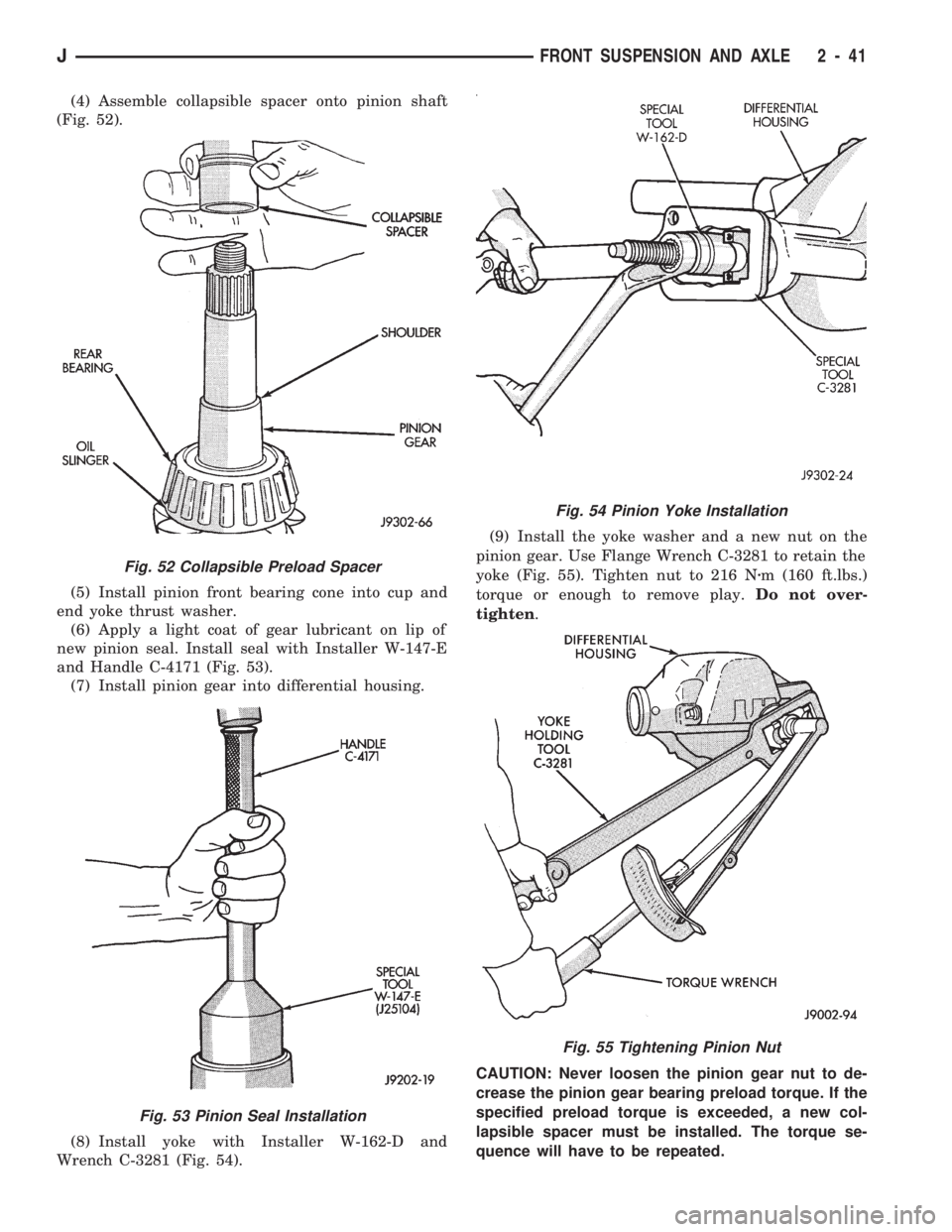
(4) Assemble collapsible spacer onto pinion shaft
(Fig. 52).
(5) Install pinion front bearing cone into cup and
end yoke thrust washer.
(6) Apply a light coat of gear lubricant on lip of
new pinion seal. Install seal with Installer W-147-E
and Handle C-4171 (Fig. 53).
(7) Install pinion gear into differential housing.
(8) Install yoke with Installer W-162-D and
Wrench C-3281 (Fig. 54).(9) Install the yoke washer and a new nut on the
pinion gear. Use Flange Wrench C-3281 to retain the
yoke (Fig. 55). Tighten nut to 216 Nzm (160 ft.lbs.)
torque or enough to remove play.Do not over-
tighten.
CAUTION: Never loosen the pinion gear nut to de-
crease the pinion gear bearing preload torque. If the
specified preload torque is exceeded, a new col-
lapsible spacer must be installed. The torque se-
quence will have to be repeated.
Fig. 52 Collapsible Preload Spacer
Fig. 53 Pinion Seal Installation
Fig. 54 Pinion Yoke Installation
Fig. 55 Tightening Pinion Nut
JFRONT SUSPENSION AND AXLE 2 - 41
Page 79 of 1784
(10) Use Flange Wrench C-3281 to retain the yoke
(Fig. 55). Slowly tighten the nut in small increments
until the rotating torque is achieved. Measure the ro-
tating torque frequently to avoid over-tightening the
nut.
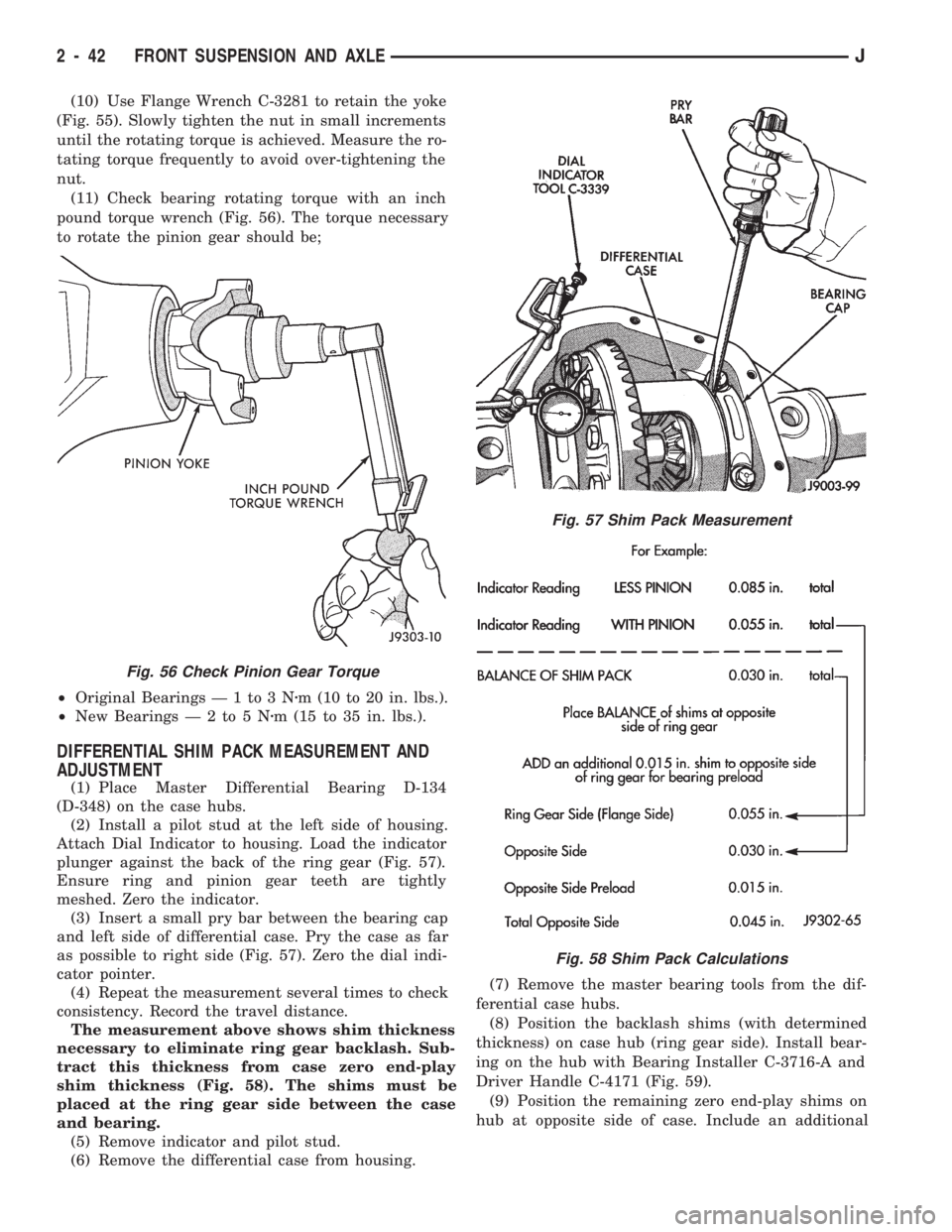
(11) Check bearing rotating torque with an inch
pound torque wrench (Fig. 56). The torque necessary
to rotate the pinion gear should be;
²Original Bearings Ð 1 to 3 Nzm (10 to 20 in. lbs.).
²New BearingsÐ2to5Nzm (15 to 35 in. lbs.).
DIFFERENTIAL SHIM PACK MEASUREMENT AND
ADJUSTMENT
(1) Place Master Differential Bearing D-134
(D-348) on the case hubs.
(2) Install a pilot stud at the left side of housing.
Attach Dial Indicator to housing. Load the indicator
plunger against the back of the ring gear (Fig. 57).
Ensure ring and pinion gear teeth are tightly
meshed. Zero the indicator.
(3) Insert a small pry bar between the bearing cap
and left side of differential case. Pry the case as far
as possible to right side (Fig. 57). Zero the dial indi-
cator pointer.
(4) Repeat the measurement several times to check
consistency. Record the travel distance.
The measurement above shows shim thickness
necessary to eliminate ring gear backlash. Sub-
tract this thickness from case zero end-play
shim thickness (Fig. 58). The shims must be
placed at the ring gear side between the case
and bearing.
(5) Remove indicator and pilot stud.
(6) Remove the differential case from housing.(7) Remove the master bearing tools from the dif-
ferential case hubs.
(8) Position the backlash shims (with determined
thickness) on case hub (ring gear side). Install bear-
ing on the hub with Bearing Installer C-3716-A and
Driver Handle C-4171 (Fig. 59).
(9) Position the remaining zero end-play shims on
hub at opposite side of case. Include an additional
Fig. 56 Check Pinion Gear Torque
Fig. 57 Shim Pack Measurement
Fig. 58 Shim Pack Calculations
2 - 42 FRONT SUSPENSION AND AXLEJ
Page 80 of 1784
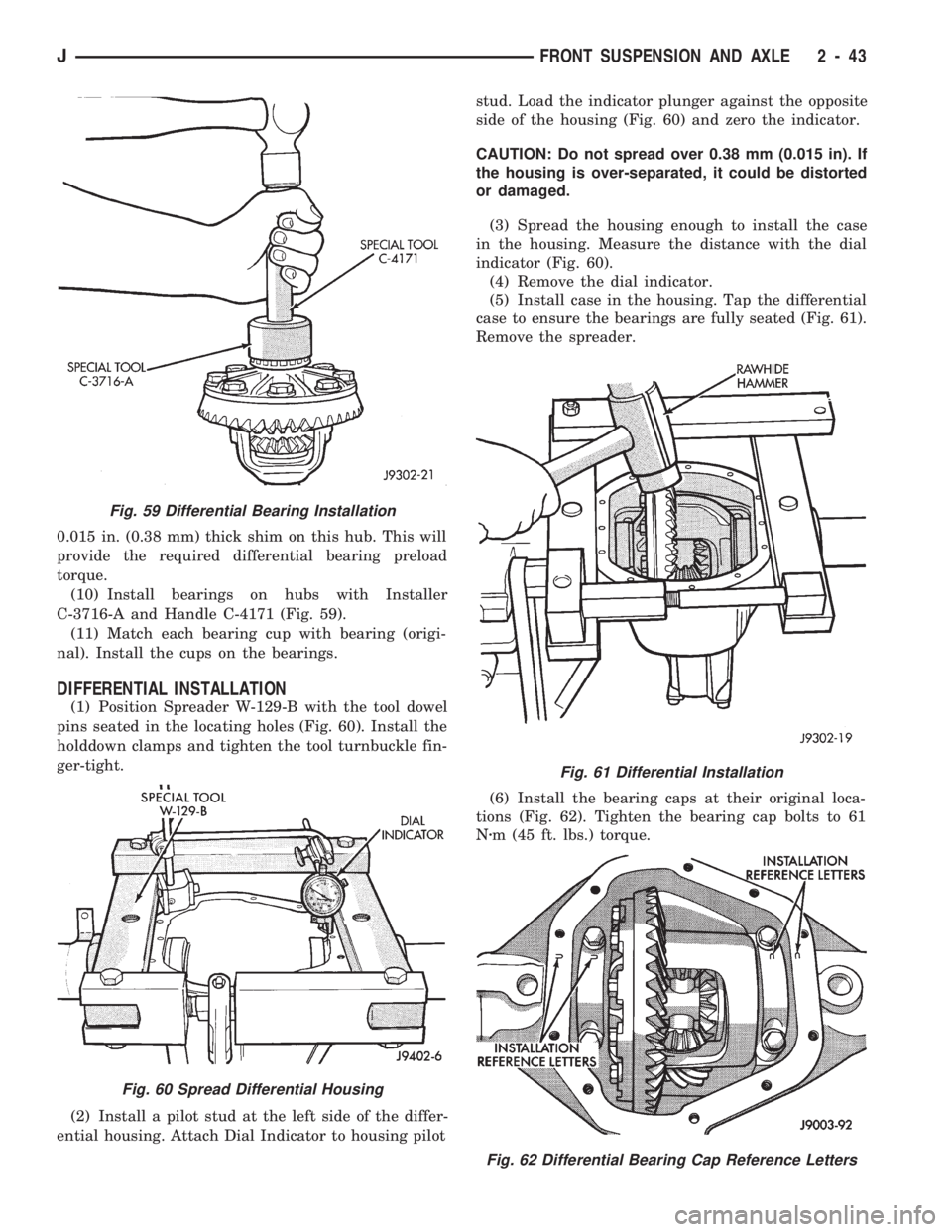
0.015 in. (0.38 mm) thick shim on this hub. This will
provide the required differential bearing preload
torque.
(10) Install bearings on hubs with Installer
C-3716-A and Handle C-4171 (Fig. 59).
(11) Match each bearing cup with bearing (origi-
nal). Install the cups on the bearings.
DIFFERENTIAL INSTALLATION
(1) Position Spreader W-129-B with the tool dowel
pins seated in the locating holes (Fig. 60). Install the
holddown clamps and tighten the tool turnbuckle fin-
ger-tight.
(2) Install a pilot stud at the left side of the differ-
ential housing. Attach Dial Indicator to housing pilotstud. Load the indicator plunger against the opposite
side of the housing (Fig. 60) and zero the indicator.
CAUTION: Do not spread over 0.38 mm (0.015 in). If
the housing is over-separated, it could be distorted
or damaged.
(3) Spread the housing enough to install the case
in the housing. Measure the distance with the dial
indicator (Fig. 60).
(4) Remove the dial indicator.
(5) Install case in the housing. Tap the differential
case to ensure the bearings are fully seated (Fig. 61).
Remove the spreader.
(6) Install the bearing caps at their original loca-
tions (Fig. 62). Tighten the bearing cap bolts to 61
Nzm (45 ft. lbs.) torque.
Fig. 59 Differential Bearing Installation
Fig. 60 Spread Differential Housing
Fig. 61 Differential Installation
Fig. 62 Differential Bearing Cap Reference Letters
JFRONT SUSPENSION AND AXLE 2 - 43
Page 81 of 1784
BACKLASH AND CONTACT PATTERN ANALYSIS
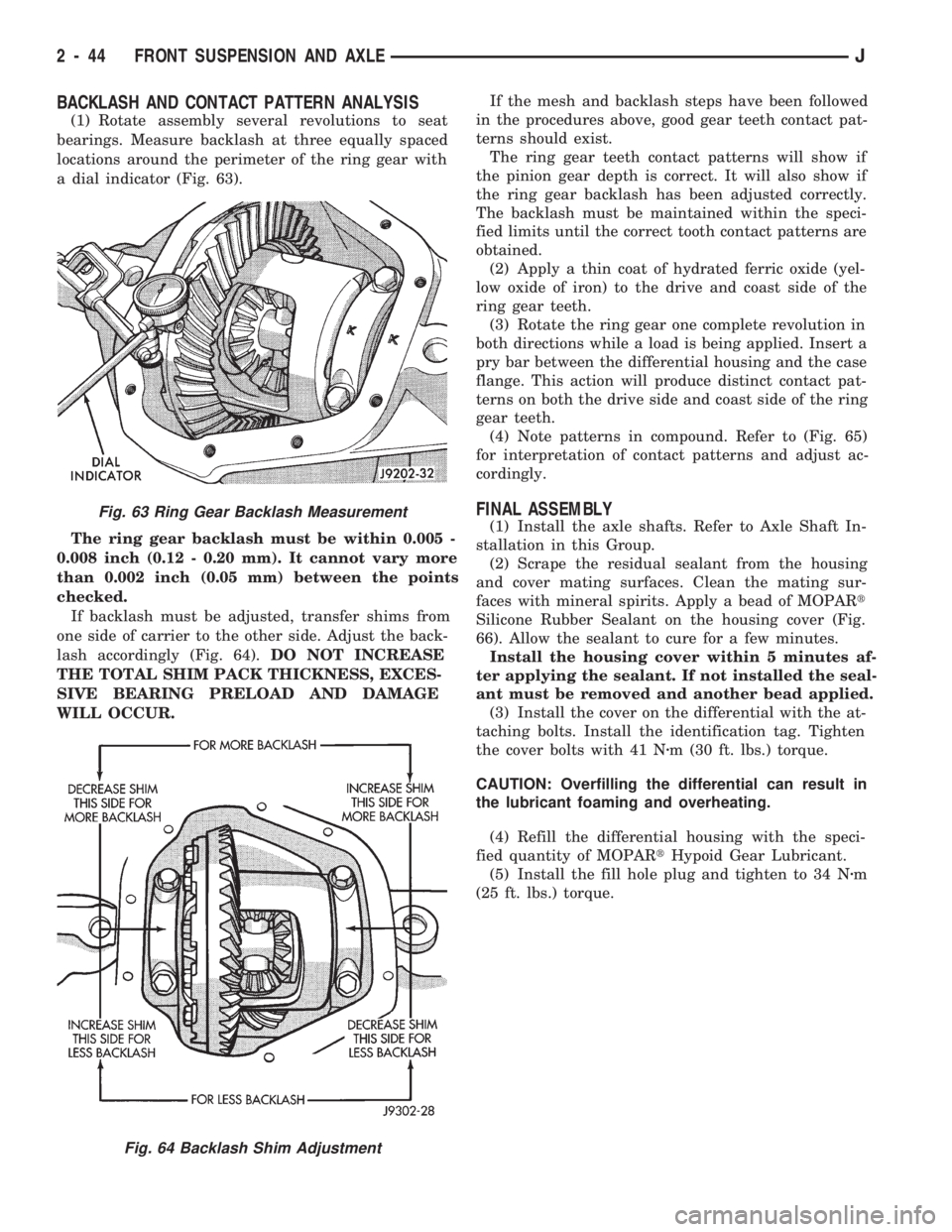
(1) Rotate assembly several revolutions to seat
bearings. Measure backlash at three equally spaced
locations around the perimeter of the ring gear with
a dial indicator (Fig. 63).
The ring gear backlash must be within 0.005 -
0.008 inch (0.12 - 0.20 mm). It cannot vary more
than 0.002 inch (0.05 mm) between the points
checked.
If backlash must be adjusted, transfer shims from
one side of carrier to the other side. Adjust the back-
lash accordingly (Fig. 64).DO NOT INCREASE
THE TOTAL SHIM PACK THICKNESS, EXCES-
SIVE BEARING PRELOAD AND DAMAGE
WILL OCCUR.If the mesh and backlash steps have been followed
in the procedures above, good gear teeth contact pat-
terns should exist.
The ring gear teeth contact patterns will show if
the pinion gear depth is correct. It will also show if
the ring gear backlash has been adjusted correctly.
The backlash must be maintained within the speci-
fied limits until the correct tooth contact patterns are
obtained.
(2) Apply a thin coat of hydrated ferric oxide (yel-
low oxide of iron) to the drive and coast side of the
ring gear teeth.
(3) Rotate the ring gear one complete revolution in
both directions while a load is being applied. Insert a
pry bar between the differential housing and the case
flange. This action will produce distinct contact pat-
terns on both the drive side and coast side of the ring
gear teeth.
(4) Note patterns in compound. Refer to (Fig. 65)
for interpretation of contact patterns and adjust ac-
cordingly.
FINAL ASSEMBLY
(1) Install the axle shafts. Refer to Axle Shaft In-
stallation in this Group.
(2) Scrape the residual sealant from the housing
and cover mating surfaces. Clean the mating sur-
faces with mineral spirits. Apply a bead of MOPARt
Silicone Rubber Sealant on the housing cover (Fig.
66). Allow the sealant to cure for a few minutes.
Install the housing cover within 5 minutes af-
ter applying the sealant. If not installed the seal-
ant must be removed and another bead applied.
(3) Install the cover on the differential with the at-
taching bolts. Install the identification tag. Tighten
the cover bolts with 41 Nzm (30 ft. lbs.) torque.
CAUTION: Overfilling the differential can result in
the lubricant foaming and overheating.
(4) Refill the differential housing with the speci-
fied quantity of MOPARtHypoid Gear Lubricant.
(5) Install the fill hole plug and tighten to 34 Nzm
(25 ft. lbs.) torque.Fig. 63 Ring Gear Backlash Measurement
Fig. 64 Backlash Shim Adjustment
2 - 44 FRONT SUSPENSION AND AXLEJ
Page 84 of 1784
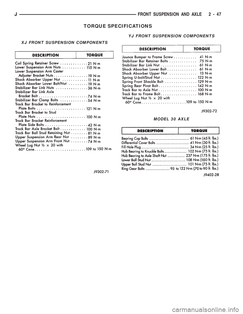
TORQUE SPECIFICATIONS
XJ FRONT SUSPENSION COMPONENTS
YJ FRONT SUSPENSION COMPONENTS
MODEL 30 AXLE
JFRONT SUSPENSION AND AXLE 2 - 47
Page 90 of 1784
(3) Install new fuel pump outlet hose. Secure with
new clamps.
(4) Connect wire terminals to motor.
(5) Install new fuel pump inlet filter.
INSTALLATIONÐYJ MODELS
(1) Install a new fuel pump inlet filter.
(2) Install fuel pump module assembly with a new
gasket between the assembly and tank. Tighten
mounting screws to 2 Nzm (18 in. lbs.) torque.
(3) Install fuel tank. Refer to Fuel Tank Installa-
tionÐYJ Models.
(4) Fill fuel tank. Install fuel tank cap.
(5) Install negative battery cable.
(6) Start vehicle and check for leaks.
FUEL PUMP ELECTRICAL CONTROL
For an electrical operational description of the fuel
pump, refer to the MFI SystemÐComponent Descrip-
tion/System Operation section of this group. See Au-
tomatic Shut Down (ASD) RelayÐPCM Output.
For the 1994 model year, the ballast resistor and
ballast resistor bypass relay are no longer used to
control the fuel pump circuit.
FUEL PRESSURE RELEASE PROCEDURE
WARNING: THE FUEL SYSTEM IS UNDER CON-
STANT FUEL PRESSURE (EVEN WITH THE ENGINE
OFF) OF APPROXIMATELY 131-269 KPA (19-39
PSI). THIS PRESSURE MUST BE RELEASED BE-
FORE SERVICING ANY FUEL SUPPLY OR FUEL RE-
TURN SYSTEM COMPONENT.
(1) Disconnect negative battery cable.
(2) Remove fuel tank filler neck cap to release fuel
tank pressure.
WARNING: DO NOT ALLOW FUEL TO SPILL ONTO
THE ENGINE INTAKE OR EXHAUST MANIFOLDS.
PLACE SHOP TOWELS UNDER AND AROUND THE
PRESSURE PORT TO ABSORB FUEL WHEN THE
PRESSURE IS RELEASED FROM THE FUEL RAIL.
WARNING: WEAR PROPER EYE PROTECTION
WHEN RELEASING FUEL SYSTEM PRESSURE.
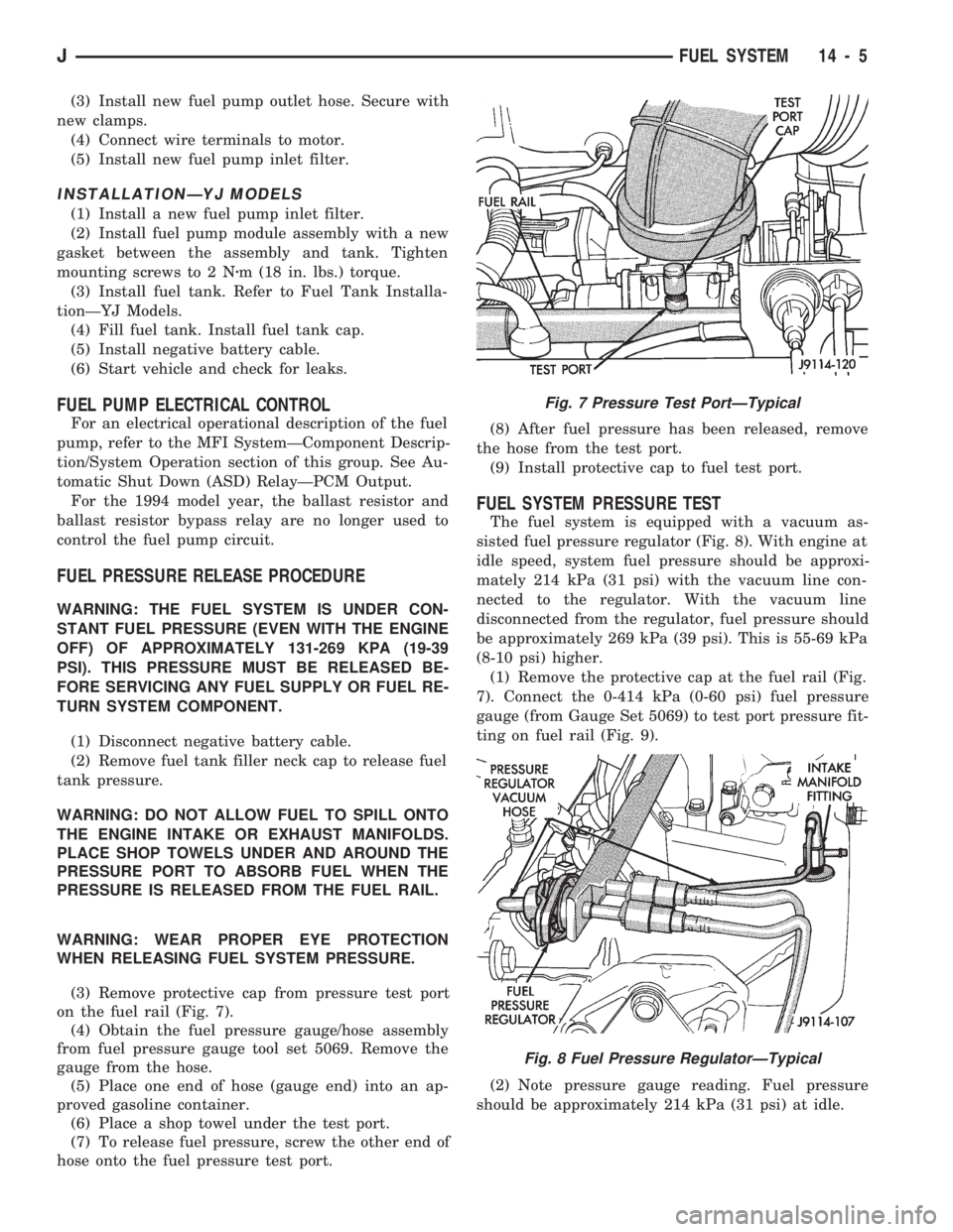
(3) Remove protective cap from pressure test port
on the fuel rail (Fig. 7).
(4) Obtain the fuel pressure gauge/hose assembly
from fuel pressure gauge tool set 5069. Remove the
gauge from the hose.
(5) Place one end of hose (gauge end) into an ap-
proved gasoline container.
(6) Place a shop towel under the test port.
(7) To release fuel pressure, screw the other end of
hose onto the fuel pressure test port.(8) After fuel pressure has been released, remove
the hose from the test port.
(9) Install protective cap to fuel test port.
FUEL SYSTEM PRESSURE TEST
The fuel system is equipped with a vacuum as-
sisted fuel pressure regulator (Fig. 8). With engine at
idle speed, system fuel pressure should be approxi-
mately 214 kPa (31 psi) with the vacuum line con-
nected to the regulator. With the vacuum line
disconnected from the regulator, fuel pressure should
be approximately 269 kPa (39 psi). This is 55-69 kPa
(8-10 psi) higher.
(1) Remove the protective cap at the fuel rail (Fig.
7). Connect the 0-414 kPa (0-60 psi) fuel pressure
gauge (from Gauge Set 5069) to test port pressure fit-
ting on fuel rail (Fig. 9).
(2) Note pressure gauge reading. Fuel pressure
should be approximately 214 kPa (31 psi) at idle.
Fig. 7 Pressure Test PortÐTypical
Fig. 8 Fuel Pressure RegulatorÐTypical
JFUEL SYSTEM 14 - 5