1994 JEEP CHEROKEE maint
[x] Cancel search: maintPage 248 of 1784
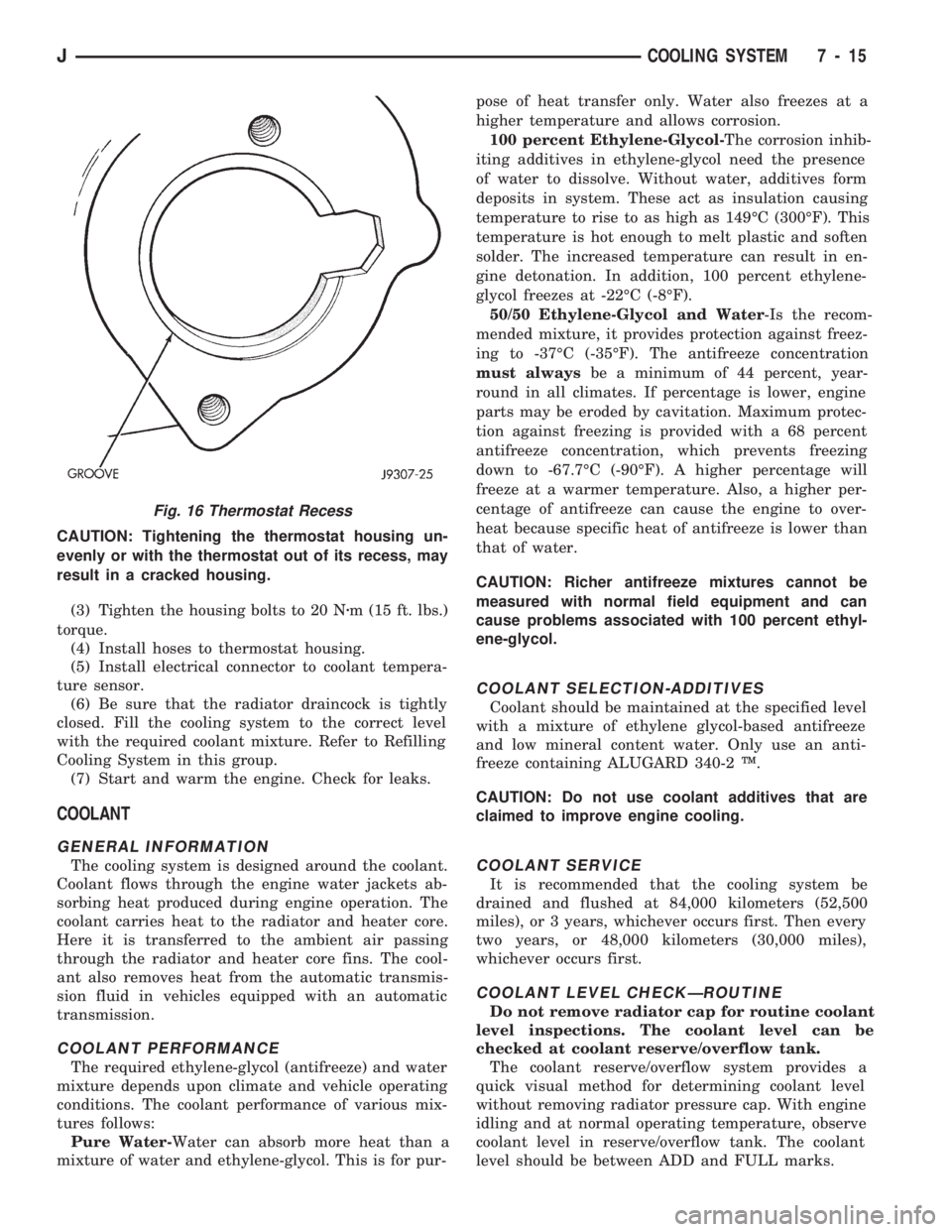
CAUTION: Tightening the thermostat housing un-
evenly or with the thermostat out of its recess, may
result in a cracked housing.
(3) Tighten the housing bolts to 20 Nzm (15 ft. lbs.)
torque.
(4) Install hoses to thermostat housing.
(5) Install electrical connector to coolant tempera-
ture sensor.
(6) Be sure that the radiator draincock is tightly
closed. Fill the cooling system to the correct level
with the required coolant mixture. Refer to Refilling
Cooling System in this group.
(7) Start and warm the engine. Check for leaks.
COOLANT
GENERAL INFORMATION
The cooling system is designed around the coolant.
Coolant flows through the engine water jackets ab-
sorbing heat produced during engine operation. The
coolant carries heat to the radiator and heater core.
Here it is transferred to the ambient air passing
through the radiator and heater core fins. The cool-
ant also removes heat from the automatic transmis-
sion fluid in vehicles equipped with an automatic
transmission.
COOLANT PERFORMANCE
The required ethylene-glycol (antifreeze) and water
mixture depends upon climate and vehicle operating
conditions. The coolant performance of various mix-
tures follows:
Pure Water-Water can absorb more heat than a
mixture of water and ethylene-glycol. This is for pur-pose of heat transfer only. Water also freezes at a
higher temperature and allows corrosion.
100 percent Ethylene-Glycol-The corrosion inhib-
iting additives in ethylene-glycol need the presence
of water to dissolve. Without water, additives form
deposits in system. These act as insulation causing
temperature to rise to as high as 149ÉC (300ÉF). This
temperature is hot enough to melt plastic and soften
solder. The increased temperature can result in en-
gine detonation. In addition, 100 percent ethylene-
glycol freezes at -22ÉC (-8ÉF).
50/50 Ethylene-Glycol and Water-Is the recom-
mended mixture, it provides protection against freez-
ing to -37ÉC (-35ÉF). The antifreeze concentration
must alwaysbe a minimum of 44 percent, year-
round in all climates. If percentage is lower, engine
parts may be eroded by cavitation. Maximum protec-
tion against freezing is provided with a 68 percent
antifreeze concentration, which prevents freezing
down to -67.7ÉC (-90ÉF). A higher percentage will
freeze at a warmer temperature. Also, a higher per-
centage of antifreeze can cause the engine to over-
heat because specific heat of antifreeze is lower than
that of water.
CAUTION: Richer antifreeze mixtures cannot be
measured with normal field equipment and can
cause problems associated with 100 percent ethyl-
ene-glycol.
COOLANT SELECTION-ADDITIVES
Coolant should be maintained at the specified level
with a mixture of ethylene glycol-based antifreeze
and low mineral content water. Only use an anti-
freeze containing ALUGARD 340-2 Ÿ.
CAUTION: Do not use coolant additives that are
claimed to improve engine cooling.
COOLANT SERVICE
It is recommended that the cooling system be
drained and flushed at 84,000 kilometers (52,500
miles), or 3 years, whichever occurs first. Then every
two years, or 48,000 kilometers (30,000 miles),
whichever occurs first.
COOLANT LEVEL CHECKÐROUTINE
Do not remove radiator cap for routine coolant
level inspections. The coolant level can be
checked at coolant reserve/overflow tank.
The coolant reserve/overflow system provides a
quick visual method for determining coolant level
without removing radiator pressure cap. With engine
idling and at normal operating temperature, observe
coolant level in reserve/overflow tank. The coolant
level should be between ADD and FULL marks.
Fig. 16 Thermostat Recess
JCOOLING SYSTEM 7 - 15
Page 249 of 1784
ADDING ADDITIONAL COOLANTÐROUTINE
Do not remove radiator cap to add coolant to
system.When adding coolant to maintain correct
level, do so at coolant reserve/overflow tank. Use a
50/50 mixture of ethylene-glycol antifreeze contain-
ing Alugard 340-2 Ÿ and low mineral content water.
Remove radiator cap only for testing or when refill-
ing system after service. Removing cap unnecessarily
can cause loss of coolant and allow air to enter sys-
tem, which produces corrosion.
COOLANT LEVEL CHECK-SERVICE
The cooling system is closed and designed to main-
tain coolant level to top of radiator.
WARNING: DO NOT OPEN RADIATOR DRAINCOCK
WITH ENGINE RUNNING OR WHILE ENGINE IS HOT
AND COOLING SYSTEM IS UNDER PRESSURE.
When vehicle servicing requires a coolant level
check in radiator, drain several ounces of coolant
from radiator drain cock. Do this while observing
coolant reserve/overflow system tank. The coolant
level in reserve/overflow tank should drop slightly. If
not, inspect for a leak between radiator and coolant
reserve/overflow system connection. Remove radiator
cap. The coolant level should be to top of radiator. If
not and if coolant level in reserve/overflow tank is at
ADD mark, check for:
²An air leak in coolant reserve/overflow tank or its
hose
²An air leak in radiator filler neck
²Leak in pressure cap seal to radiator filler neck
LOW COOLANT LEVEL-AERATION
If the coolant level in radiator drops below top of
radiator core tubes, air will enter cooling system.
Low coolant level can cause thermostat pellet to be
suspended in air instead of coolant. This will cause
thermostat to open later, which in turn causes higher
coolant temperature. Air trapped in cooling system
also reduces amount of coolant circulating in heater
core resulting in low heat output.
DEAERATION
As the engine operates, any air trapped in cooling
system gathers under the radiator cap. The next time
the engine is operated, thermal expansion of coolant
will push any trapped air past radiator cap into the
coolant reserve/overflow tank. Here it escapes to the
atmosphere into the tank. When the engine cools
down the coolant, it will be drawn from the reserve/
overflow tank into the radiator to replace any re-
moved air.
DRAINING COOLING SYSTEM
ALL MODELSÐEXCEPT XJ WITH 4.0L ENGINE
WARNING: DO NOT REMOVE THE CYLINDER
BLOCK DRAIN PLUGS OR LOOSEN THE RADIATOR
DRAINCOCK WITH SYSTEM HOT AND UNDER
PRESSURE. SERIOUS BURNS FROM COOLANT
CAN OCCUR.
DO NOT WASTE reusable coolant. If the solution
is clean, drain the coolant into a clean container for
reuse.
DO NOT remove the radiator cap when draining
the coolant from the reserve/overflow tank. Open the
radiator draincock and when the tank is empty, re-
move the radiator cap. The coolant does not have to
be removed from the tank unless the system is being
refilled with a fresh mixture.
(1) Drain the coolant from the radiator by loosen-
ing the draincock.
(2) Drain coolant from engine as follows:
(a) On 2.5L engines (all models) by removing
drain plug at left rear side of block.
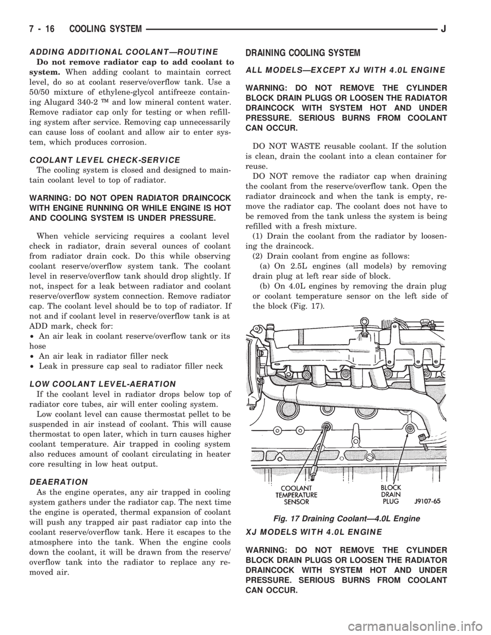
(b) On 4.0L engines by removing the drain plug
or coolant temperature sensor on the left side of
the block (Fig. 17).
XJ MODELS WITH 4.0L ENGINE
WARNING: DO NOT REMOVE THE CYLINDER
BLOCK DRAIN PLUGS OR LOOSEN THE RADIATOR
DRAINCOCK WITH SYSTEM HOT AND UNDER
PRESSURE. SERIOUS BURNS FROM COOLANT
CAN OCCUR.
Fig. 17 Draining CoolantÐ4.0L Engine
7 - 16 COOLING SYSTEMJ
Page 253 of 1784

The coolant reserve/overflow system consists of a
radiator mounted pressurized cap, a plastic reserve/
overflow tank (Figs. 21, 22 or 23), a tube connecting
the radiator and tank, and an overflow tube on the
side of the tank.
TANK REMOVAL/INSTALLATION
(1) Remove the tube clamp at the tank and remove
tube.(2) On YJ models, remove the windshield washer
reservoir and its mounting bracket.
(3) Remove the tank mounting bolts and remove
tank.
(4) Reverse the preceding steps for installation.
RADIATOR PRESSURE CAP
All radiators are equipped with a pressure cap.
This cap releases pressure at some point within a
range of 83-110 kPa (12-16 psi). The pressure relief
point (in pounds) is engraved on top of the cap (Fig.
24).
The cooling system will operate at pressures
slightly above atmospheric pressure. This results in a
higher coolant boiling point allowing increased radi-
ator cooling capacity. The cap (Fig. 24) contains a
spring-loaded pressure relief valve. This valve opens
when system pressure reaches the release range of
83-110 kPa (12-16 psi).
A vent valve in the center of the cap allows a small
coolant flow through the cap when coolant is below
boiling temperature. The valve is completely closed
when boiling point is reached. As coolant cools, it
contracts and creates a vacuum in the cooling sys-
tem. This causes the vacuum valve to open and cool-
ant in reserve/overflow tank to be drawn through
connecting hose into radiator. If the vacuum valve is
stuck shut, radiator hoses will collapse on cool-down.
A rubber gasket seals the radiator filler neck. This
is done to maintain vacuum during coolant cool-down
and to prevent leakage when system is under pres-
sure.
Fig. 21 Reserve/Overflow TankÐYJ Models
Fig. 22 Reserve/Overflow TankÐXJ ModelsÐExcept
Right Hand Drive
Fig. 23 Reserve/Overflow TankÐXJ ModelsÐWith
Right Hand Drive
7 - 20 COOLING SYSTEMJ
Page 267 of 1784
BELT TENSIONÐRIGHT HAND DRIVE (RHD)
XJ MODELS WITH 4.0L ENGINE
It is not necessary to adjust belt tension on RHD
vehicles if equipped with a 4.0L engine. The engine
is equipped with an automatic belt tensioner (Fig. 7).
The tensioner maintains correct belt tension at all
times.Due to the use of this belt tensioner, DO
NOT attempt to use a belt tension gauge on this
engine.
BELT TENSION SPECIFICATIONS
Refer to the Specifications section at the end of this
group.
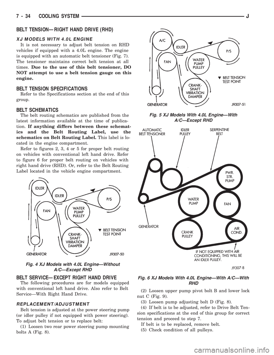
BELT SCHEMATICS
The belt routing schematics are published from the
latest information available at the time of publica-
tion.If anything differs between these schemat-
ics and the Belt Routing Label, use the
schematics on Belt Routing Label.This label is lo-
cated in the engine compartment.
Refer to figures 2, 3, 4 or 5 for proper belt routing
on vehicles with conventional left hand drive. Refer
to figure 6 for proper belt routing on vehicles with
right hand drive (RHD). Or, refer to the Belt Routing
Label located in the vehicle engine compartment.
BELT SERVICEÐEXCEPT RIGHT HAND DRIVE
The following procedures are for models equipped
with conventional left hand drive. Also refer to Belt
ServiceÐWith Right Hand Drive.
REPLACEMENT/ADJUSTMENT
Belt tension is adjusted at the power steering pump
(or idler pulley if not equipped with power steering).
To adjust belt tension or to replace belt:
(1) Loosen two rear power steering pump mounting
bolts A (Fig. 8).(2) Loosen upper pump pivot bolt B and lower lock
nut C (Fig. 9).
(3) Loosen pump adjusting bolt D (Fig. 8).
(4) If belt is to be adjusted, refer to Drive Belt Ten-
sion specifications at the end of this group for correct
tension and proceed to step 7.
If belt is to be replaced, remove belt.
(5) Check condition of all pulleys.
Fig. 4 XJ Models with 4.0L EngineÐWithout
A/CÐExcept RHD
Fig. 5 XJ Models With 4.0L EngineÐWith
A/CÐExcept RHD
Fig. 6 XJ Models With 4.0L EngineÐWith A/CÐWith
RHD
7 - 34 COOLING SYSTEMJ
Page 271 of 1784
SPECIFICATIONS
GENERAL INFORMATION
The following specifications are published from the
latest information available at the time of publica-
tion.If anything differs between the specifica-
tions found on the Vehicle Emission Control
Information (VECI) label and the following
specifications, use specifications on VECI label.
The VECI label is located in the engine compart-
ment.
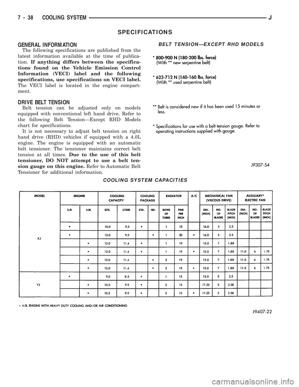
DRIVE BELT TENSION
Belt tension can be adjusted only on models
equipped with conventional left hand drive. Refer to
the following Belt TensionÐExcept RHD Models
chart for specifications.
It is not necessary to adjust belt tension on right
hand drive (RHD) vehicles if equipped with a 4.0L
engine. The engine is equipped with an automatic
belt tensioner. The tensioner maintains correct belt
tension at all times.Due to the use of this belt
tensioner, DO NOT attempt to use a belt ten-
sion gauge on this engine.Refer to Automatic Belt
Tensioner for additional information.
COOLING SYSTEM CAPACITIES
BELT TENSIONÐEXCEPT RHD MODELS
7 - 38 COOLING SYSTEMJ
Page 275 of 1784
BATTERY TEST PROCEDURES
INDEX
page page
Battery Charging.......................... 5
Battery Diagnostics Chart................... 7
Battery Load Test......................... 4
Battery Open Circuit Voltage Test............. 3Battery Testing General Information........... 3
General Information........................ 2
Hydrometer Test.......................... 3
Specifications............................ 8
GENERAL INFORMATION
The battery stores, stabilizes, and produces electri-
cal current. A battery must be able to accept a
charge and produce high-amperage current output
over an extended period. A chemical reaction occurs
between the sulfuric acid solution (electrolyte) and
the lead +/þ plates in each cell of the battery. As
the battery discharges, the plates collect the acid
from the electrolyte. When the charging system
charges the battery, water is converted to sulfuric
acid in the battery. The amount of acid (specific
gravity) in the electrolyte can be measured with a
hydrometer. The battery is vented to release gases
that are created when the battery is being charged.
The battery top,posts, and terminals should be cleaned when other
underhood maintenance is performed.
WARNING: DO NOT ATTEMPT TO ASSIST BOOST,
CHARGE, OR TEST BATTERY WHEN ELECTRO-
LYTE LEVEL IS BELOW THE TOP OF THE PLATES.
PERSONAL INJURY MAY OCCUR.
When the electrolyte level is below the top of the
plates distilled water should be added. The battery
must be completely charged. The top, posts, and ter-
minals should be properly cleaned before diagnostic
procedures are performed. See Group 8B - Battery/
Starter/Generator Service, for additional information.
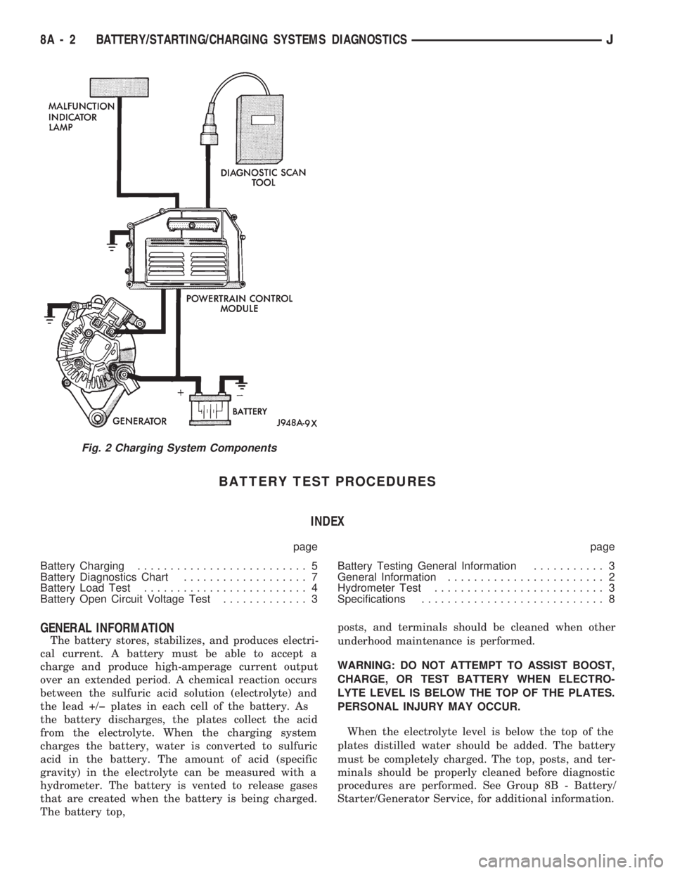
Fig. 2 Charging System Components
8A - 2 BATTERY/STARTING/CHARGING SYSTEMS DIAGNOSTICSJ
Page 277 of 1784
Battery/Starter/Generator Service for instructions. To
test battery no load voltage, perform the following
operation:
(1) Before measuring open circuit voltage, the sur-
face charge must be removed from plates. Turn head-
lamps on for 15 seconds then allow up to 5 minutes
for voltage to stabilize.
(2) Remove both battery cables, negative first.
(3) Using a voltmeter connected to the battery
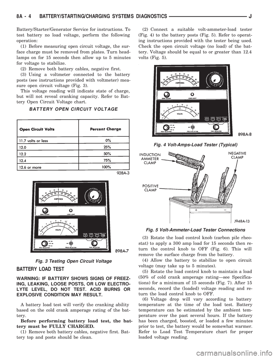
posts (see instructions provided with voltmeter) mea-
sure open circuit voltage (Fig. 3).
This voltage reading will indicate state of charge,
but will not reveal cranking capacity. Refer to Bat-
tery Open Circuit Voltage chart.
BATTERY LOAD TEST
WARNING: IF BATTERY SHOWS SIGNS OF FREEZ-
ING, LEAKING, LOOSE POSTS, OR LOW ELECTRO-
LYTE LEVEL, DO NOT TEST. ACID BURNS OR
EXPLOSIVE CONDITION MAY RESULT.
A battery load test will verify the cranking ability
based on the cold crank amperage rating of the bat-
tery.
Before performing battery load test, the bat-
tery must be FULLY CHARGED.
(1) Remove both battery cables, negative first. Bat-
tery top and posts should be clean.(2) Connect a suitable volt-ammeter-load tester
(Fig. 4) to the battery posts (Fig. 5). Refer to operat-
ing instructions provided with the tester being used.
Check the open circuit voltage (no load) of the bat-
tery. Voltage should be equal to or greater than 12.4
volts (Fig. 5).
(3) Rotate the load control knob (carbon pile rheo-
stat) to apply a 300 amp load for 15 seconds then re-
turn the control knob to OFF (Fig. 6). This will
remove the surface charge from the battery.
(4) Allow the battery to stabilize to open circuit
voltage (may take up to 5 minutes).
(5) Rotate the load control knob to maintain a load
(50% of cold crank amperage ratingÐsee Specifica-
tions) for a minimum of 15 seconds (Fig. 7). After 15
seconds, record the (loaded) voltage reading and re-
turn the load control knob to OFF.
(6) Voltage drop will vary according to battery
temperature at the time of the load test. Battery
temperature can be estimated by the ambient tem-
perature over the past several hours. If the battery
has been charged, boosted, or loaded a few minutes
prior to test, the battery would be somewhat warmer.
Refer to Load Test Temperature chart for proper
loaded voltage reading.
Fig. 4 Volt-Amps-Load Tester (Typical)
Fig. 5 Volt-Ammeter-Load Tester Connections
BATTERY OPEN CIRCUIT VOLTAGE
Fig. 3 Testing Open Circuit Voltage
8A - 4 BATTERY/STARTING/CHARGING SYSTEMS DIAGNOSTICSJ
Page 294 of 1784
BATTERY/STARTER/GENERATOR SERVICE
CONTENTS
page page
BATTERY SERVICE PROCEDURES.......... 1
ENGINE STARTER MOTOR SERVICE
PROCEDURES......................... 4GENERATOR SERVICE PROCEDURES........ 7
SPECIFICATIONS....................... 10
BATTERY SERVICE PROCEDURES
GENERAL INFORMATION
This section covers battery removal and installa-
tion procedures only. For diagnostic procedures, refer
to Group 8A - Battery/Starting/Charging Systems Di-
agnostics.
BATTERY MAINTENANCE
(1) Inspect cable terminals for corrosion and dam-
age. Remove the corrosion using a wire brush, or
post and terminal cleaner, and a sodium bicarbonate/
water solution. Replace cables that have damaged or
deformed terminals.
Be sure filler caps or vents are installed when
washing battery to prevent solution from enter-
ing battery.
(2) Clean outside of battery case if the original
battery is to be installed. Clean top cover with di-
luted ammonia or a sodium bicarbonate/water solu-
tion to remove acid film. Flush with clean water.
Ensure that cleaning solution does not enter cells.
(3) Remove corrosion from the terminals with a
wire brush or post and terminal cleaner. Inspect the
case for cracks or other damage that would result in
leakage of electrolyte.
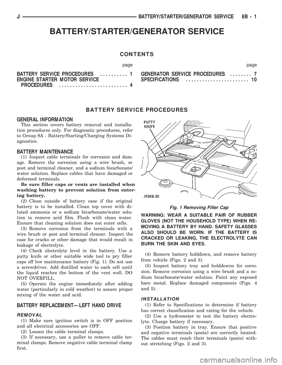
(4) Check electrolyte level in the battery. Use a
putty knife or other suitable wide tool to pry filler
caps off low maintenance battery (Fig. 1). Do not use
a screwdriver. Add distilled water to each cell until
the liquid reaches the bottom of the vent well. DO
NOT OVERFILL.
(5) Operate the engine immediately after adding
water (particularly in cold weather) to assure proper
mixing of the water and acid.
BATTERY REPLACEMENTÐLEFT HAND DRIVE
REMOVAL
(1) Make sure ignition switch is in OFF position
and all electrical accessories are OFF.
(2) Loosen the cable terminal clamps.
(3) If necessary, use a puller to remove cable ter-
minal clamps. Remove negative cable terminal clamp
first.WARNING: WEAR A SUITABLE PAIR OF RUBBER
GLOVES (NOT THE HOUSEHOLD TYPE) WHEN RE-
MOVING A BATTERY BY HAND. SAFETY GLASSES
ALSO SHOULD BE WORN. IF THE BATTERY IS
CRACKED OR LEAKING, THE ELECTROLYTE CAN
BURN THE SKIN AND EYES.
(4) Remove battery holddown, and remove battery
from vehicle (Figs. 2 and 3).
(5) Inspect battery tray and holddowns for corro-
sion. Remove corrosion using a wire brush and a so-
dium bicarbonate/water solution. Paint any exposed
bare metal. Replace damaged components (Figs. 4
and 5).
INSTALLATION
(1) Refer to Specifications to determine if battery
has correct classification and rating for the vehicle.
(2) Use a hydrometer to test the battery electro-
lyte. Charge battery if necessary.
(3) Position battery in tray. Ensure that positive
and negative terminals (posts) are correctly located.
The cables must reach their terminals (posts) with-
out stretching (Figs. 2 and 3).
Fig. 1 Removing Filler Cap
JBATTERY/STARTER/GENERATOR SERVICE 8B - 1