1994 JEEP CHEROKEE maint
[x] Cancel search: maintPage 136 of 1784
DRB SCAN TOOL
For operation of the DRB scan tool, refer to the ap-
propriate Powertrain Diagnostic Procedures service
manual.
DIAGNOSTIC TROUBLE CODE (DTC)
On the following pages, a list of diagnostic trouble
codes is provided for the 2.5L 4 cylinder and 4.0L 6
cylinder engines. A DTC indicates that the power-
train control module (PCM) has recognized an abnor-
mal signal in a circuit or the system. A DTC may
indicate the result of a failure, but never identify the
failed component directly.
DIAGNOSTIC TROUBLE CODE DESCRIPTIONS
Diagnostic
Trouble
CodeDRB Scan Tool
DisplayDescription of Diagnostic Trouble Code
11* .......... NoCrank Reference
Signal at PCMNo crank reference signal detected during engine cranking.
12* ..........Battery Disconnect Direct battery input to PCM was disconnected within the last 50 Key-on
cycles.
13**.......... NoChange in MAP From
Start to RunNo difference recognized between the engine MAP reading and the
barometric (atmospheric) pressure reading at start-up.
14**.......... MAPSensor Voltage Too
LowMAP sensor input below minimum acceptable voltage.
or
MAP Sensor Voltage Too
HighMAP sensor input above maximum acceptable voltage.
15**.......... NoVehicle Speed Sensor
SignalNo vehicle distance (speed) sensor signal detected during road load
conditions.
17* ..........Engine is Cold Too Long Engine coolant temperature remains below normal operating temperatures
during vehicle travel (thermostat).
21**.......... O2SStays at Center Neither rich or lean condition detected from the oxygen sensor input.
or
O2S Shorted to Voltage Oxygen sensor input voltage maintained above the normal operating range.
22**.......... ECTSensor Voltage Too
HighEngine coolant temperature sensor input above maximum acceptable
voltage.
or
ECT Sensor Voltage Too
LowEngine coolant temperature sensor input below minimum acceptable voltage.
* Check Engine Lamp will not illuminate at all times if this Diagnostic Trouble Code was recorded. Cycle Ignition key as
described in manual and observe code flashed by Check Engine lamp.
** Check Engine Lamp will illuminate during engine operation if this Diagnostic Trouble Code was recorded.
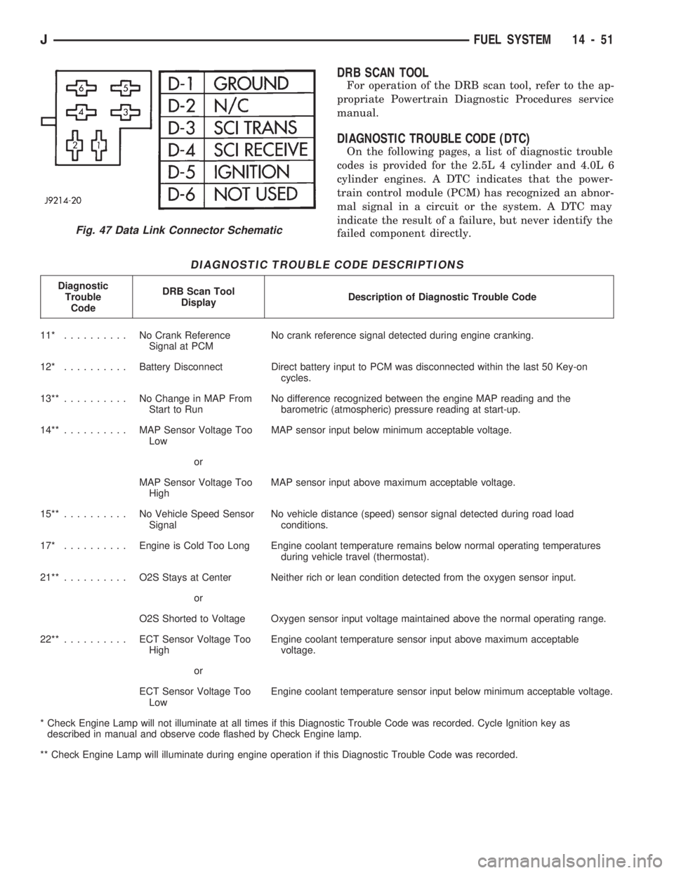
Fig. 47 Data Link Connector Schematic
JFUEL SYSTEM 14 - 51
Page 162 of 1784
CAUTION: Do not allow the master cylinder reser-
voir to run dry while bleeding the brakes. Running
dry will allow air to re-enter the system making a
second bleeding operation necessary.
(6) Perform ``Bleed Brake'' procedure with DRB II
scan tool. Procedure is described in DRB II software
information and diagnostic manual.
(a) Connect DRB II scan tool to diagnostic con-
nector.
(b) Run Bleed Brake procedure as described in
tester manual.
(7) Repeat conventional bleeding procedure out-
lined in steps (1) through (8).
(8) Top off master cylinder fluid level if necessary.
(9) Verify proper brake operation.
BRAKELINES AND HOSES
Metal brakelines and rubber brake hoses should be
inspected periodically and replaced if damaged.
Rubber brake hoses should be replaced if cut,
cracked, swollen, or leaking. Rubber hoses must be
replaced. They are not repairable parts.
When installing new, or original brakelines andhoses, lubricate the fitting threads with brake fluid
before connection.
The steel brakelines should be checked every time
the vehicle is in for normal maintainence. This is im-
portant on high mileage vehicles. It is even more im-
portant when a vehicle is operated in areas where
salt is used regularly on the road surface during win-
ter.
Heavily rusted/corroded brake rotors, drums, sup-
port plates, and brakelines should be cleaned and
carefully inspected. Heavy rust buildup can hide se-
vere damge to a component. Severely rusted parts
should be replaced if you are unsure about their con-
dition.
COMBINATION VALVE
The combination valve is not a serviceable part.
The valve must be replaced if a malfunction occurs.
BRAKELINE CHARTS
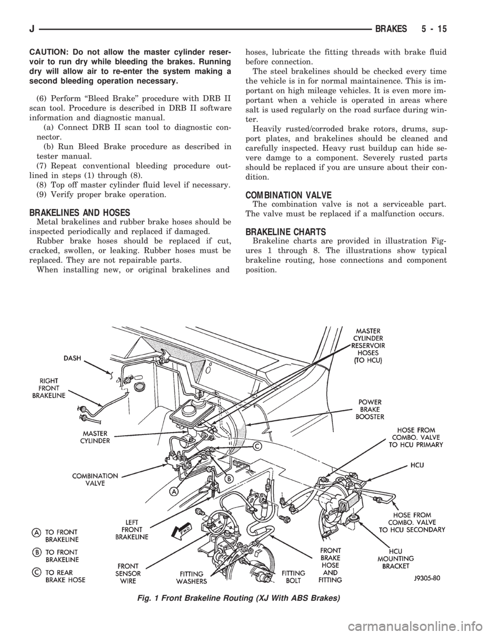
Brakeline charts are provided in illustration Fig-
ures 1 through 8. The illustrations show typical
brakeline routing, hose connections and component
position.
Fig. 1 Front Brakeline Routing (XJ With ABS Brakes)
JBRAKES 5 - 15
Page 172 of 1784
enough to maintain contact between the piston and
inboard brakeshoe. Brakelining running clearance at
the rotor, will be held between zero and a maximum
of 0.12 mm (0.005 in.).
DISC BRAKESHOE REMOVAL
(1) Raise vehicle and remove front wheels.
(2) Drain small amount of fluid from master cylin-
der front brake reservoir with suction gun.
(3) Bottom caliper piston in bore with C-clamp. Po-
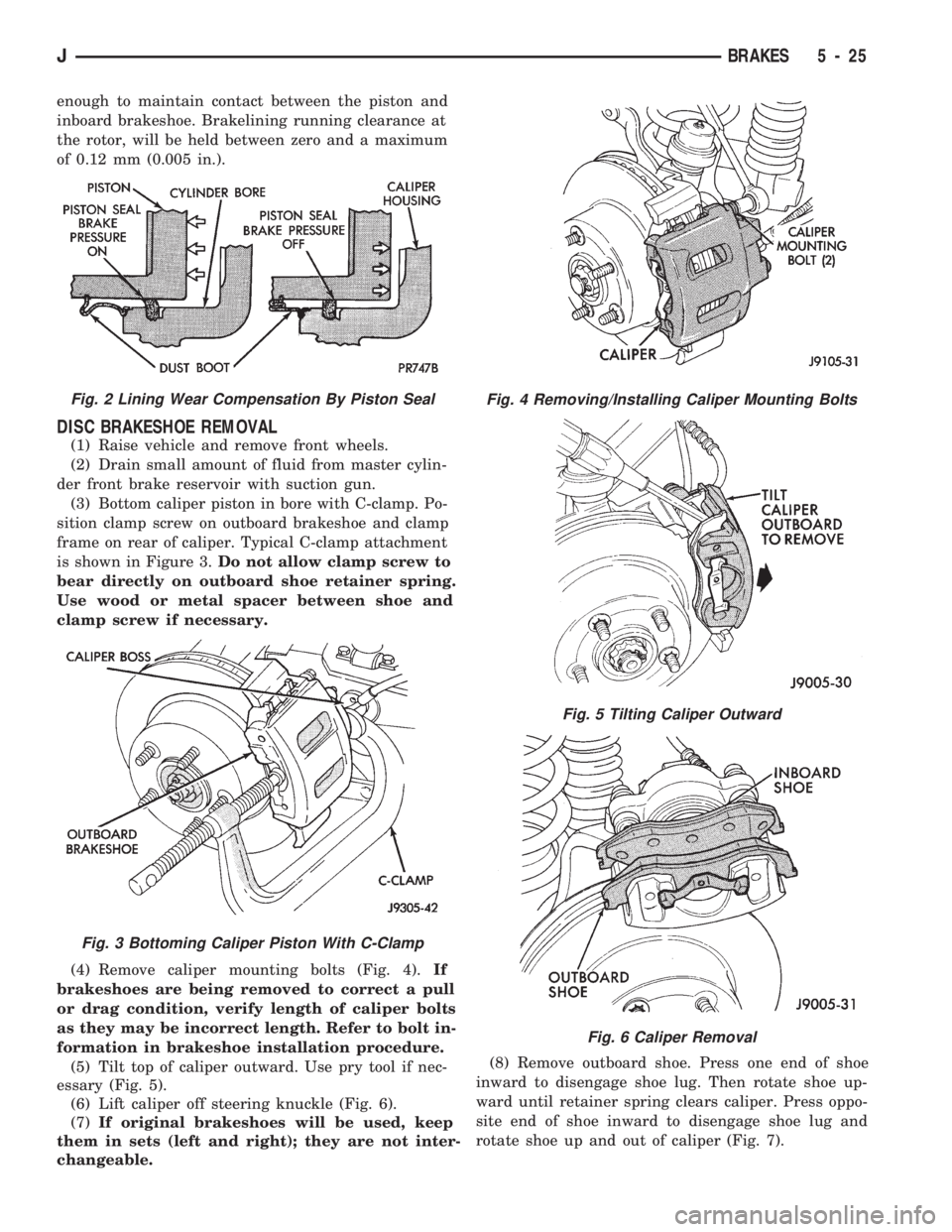
sition clamp screw on outboard brakeshoe and clamp
frame on rear of caliper. Typical C-clamp attachment
is shown in Figure 3.Do not allow clamp screw to
bear directly on outboard shoe retainer spring.
Use wood or metal spacer between shoe and
clamp screw if necessary.
(4) Remove caliper mounting bolts (Fig. 4).If
brakeshoes are being removed to correct a pull
or drag condition, verify length of caliper bolts
as they may be incorrect length. Refer to bolt in-
formation in brakeshoe installation procedure.
(5) Tilt top of caliper outward. Use pry tool if nec-
essary (Fig. 5).
(6) Lift caliper off steering knuckle (Fig. 6).
(7)If original brakeshoes will be used, keep
them in sets (left and right); they are not inter-
changeable.(8) Remove outboard shoe. Press one end of shoe
inward to disengage shoe lug. Then rotate shoe up-
ward until retainer spring clears caliper. Press oppo-
site end of shoe inward to disengage shoe lug and
rotate shoe up and out of caliper (Fig. 7).
Fig. 2 Lining Wear Compensation By Piston Seal
Fig. 3 Bottoming Caliper Piston With C-Clamp
Fig. 4 Removing/Installing Caliper Mounting Bolts
Fig. 5 Tilting Caliper Outward
Fig. 6 Caliper Removal
JBRAKES 5 - 25
Page 190 of 1784
ANTILOCK BRAKE SYSTEM OPERATION
INDEX
page page
ABS Operation in Antilock Braking Mode....... 43
ABS Operation in Normal Braking Mode....... 43
Acceleration Switch Operation............... 45
ECY Operation.......................... 46HCU Pump and Pedal Travel Sensor Operation . 44
HCU Solenoid Valve Operation.............. 43
System Power-Up and Initialization........... 43
Wheel Speed Sensor Operation............. 45
SYSTEM POWER-UP AND INITIALIZATION
The antilock system is in standby mode with the
ignition switch in Off or Accessory position. The an-
tilock electrical components are not operational.
Turning the ignition switch to On or Run position
allows battery voltage to flow through the switch to
the ECU ignition terminal.
The ABS system is activated when battery voltage
is supplied to the ECU. The ECU performs a system
initialization procedure at this point. Initialization
consists of a static and dynamic self check of system
electrical components.
The static check occurs immediately after the igni-
tion switch is turned to the On position. The dynamic
check occurs when vehicle road speed reaches ap-
proximately 10 kph (6 mph). During the dynamic
check, the ECU briefly cycles the pump to verify op-
eration. The HCU solenoids are checked continu-
ously.
If an ABS component exhibits a fault during ini-
tialization, the ECU illuminates the amber warning
light and registers a fault code in the microprocessor
memory.
ABS OPERATION IN NORMAL BRAKING MODE
The ECU monitors wheel speed sensor inputs con-
tinuously while the vehicle is in motion. However,
the ECU will not activate any ABS components as
long as sensor inputs and the acceleration switch in-
dicate normal braking.
During normal braking, the master cylinder, power
booster and wheel brake units all function as they
would in a vehicle without ABS. The HCU compo-
nents are not activated.
ABS OPERATION IN ANTILOCK BRAKING MODE
The purpose of the antilock system is to prevent
wheel lockup during periods of high wheel slip. Pre-
venting lockup helps maintain vehicle braking action
and steering control.
The antilock ECU activates the system whenever
sensor signals indicate periods of high wheel slip.
High wheel slip can be described as the point where
wheel rotation begins approaching zero (or lockup)
during braking. Periods of high wheel slip occur
when brake stops involve high pedal pressure and
rate of vehicle deceleration.The antilock system retards lockup during high
slip conditions by modulating fluid apply pressure to
the wheel brake units.
Brake fluid apply pressure is modulated according
to wheel speed, degree of slip and rate of decelera-
tion. A sensor at each wheel converts wheel speed
into electrical signals. These signals are transmitted
to the ECU for processing and determination of
wheel slip and deceleration rate.
The Jeep ABS system has three fluid pressure con-
trol channels. The front brakes are controlled sepa-
rately and the rear brakes in tandem (Fig. 10). A
speed sensor input signal indicating high slip condi-
tions activates the ECU antilock program.
Two solenoid valves are used in each antilock con-
trol channel (Fig. 11). The valves are all located
within the HCU valve body and work in pairs to ei-
ther increase, hold, or decrease apply pressure as
needed in the individual control channels.
The solenoid valves are not static during antilock
braking. They are cycled continuously to modulate
pressure. Solenoid cycle time in antilock mode can be
measured in milliseconds.
HCU SOLENOID VALVE OPERATION
Normal Braking
During normal braking, the HCU solenoid valves
and pump are not activated. The master cylinder and
power booster operate the same as a vehicle without
an ABS brake system.
Antilock Pressure Modulation
Solenoid valve pressure modulation occurs in three
stages which are: pressure increase, pressure hold,
and pressure decrease. The valves are all contained
in the valve body portion of the HCU.
Pressure Decrease
The outlet valve is opened and the inlet valve is
closed during the pressure decrease cycle (Fig. 11).
A pressure decrease cycle is initiated when speed
sensor signals indicate high wheel slip at one or
more wheels. At this point, the ECU opens the outlet
valve. Opening the outlet valve also opens the hy-
draulic return circuit to the master cylinder reser-
JANTILOCK BRAKE SYSTEM OPERATION 5 - 43
Page 191 of 1784
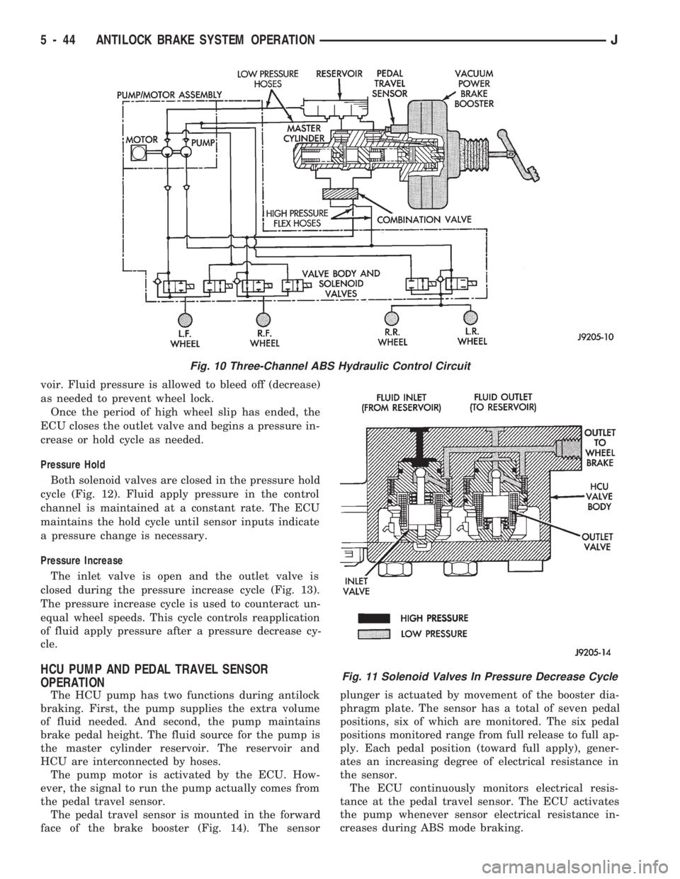
voir. Fluid pressure is allowed to bleed off (decrease)
as needed to prevent wheel lock.
Once the period of high wheel slip has ended, the
ECU closes the outlet valve and begins a pressure in-
crease or hold cycle as needed.
Pressure Hold
Both solenoid valves are closed in the pressure hold
cycle (Fig. 12). Fluid apply pressure in the control
channel is maintained at a constant rate. The ECU
maintains the hold cycle until sensor inputs indicate
a pressure change is necessary.
Pressure Increase
The inlet valve is open and the outlet valve is
closed during the pressure increase cycle (Fig. 13).
The pressure increase cycle is used to counteract un-
equal wheel speeds. This cycle controls reapplication
of fluid apply pressure after a pressure decrease cy-
cle.
HCU PUMP AND PEDAL TRAVEL SENSOR
OPERATION
The HCU pump has two functions during antilock
braking. First, the pump supplies the extra volume
of fluid needed. And second, the pump maintains
brake pedal height. The fluid source for the pump is
the master cylinder reservoir. The reservoir and
HCU are interconnected by hoses.
The pump motor is activated by the ECU. How-
ever, the signal to run the pump actually comes from
the pedal travel sensor.
The pedal travel sensor is mounted in the forward
face of the brake booster (Fig. 14). The sensorplunger is actuated by movement of the booster dia-
phragm plate. The sensor has a total of seven pedal
positions, six of which are monitored. The six pedal
positions monitored range from full release to full ap-
ply. Each pedal position (toward full apply), gener-
ates an increasing degree of electrical resistance in
the sensor.
The ECU continuously monitors electrical resis-
tance at the pedal travel sensor. The ECU activates
the pump whenever sensor electrical resistance in-
creases during ABS mode braking.
Fig. 10 Three-Channel ABS Hydraulic Control Circuit
Fig. 11 Solenoid Valves In Pressure Decrease Cycle
5 - 44 ANTILOCK BRAKE SYSTEM OPERATIONJ
Page 203 of 1784
PARKING BRAKES
INDEX
page page
General Service Information................ 56
Parking Brake Adjustment (XJ/YJ)............ 63
Parking Brake Cable Tensioner Replacement (XJ).61
Parking Brake Front Cable Replacement (YJ) . . . 62
Parking Brake Lever Installation
(XJ with Full Console)................... 60
Parking Brake Lever Installation
(XJ with Mini Console)................... 58
Parking Brake Lever Installation
(XJ Without Console).................... 60
Parking Brake Lever Removal
(XJ with Full Console).................... 59
Parking Brake Lever Removal
(XJ with Mini Console)................... 58
Parking Brake Lever Removal (XJ Without Console).60
Parking Brake Operation................... 56
Parking Brake Pedal Installation (YJ).......... 61
Parking Brake Pedal Removal (YJ)........... 61
Parking Brake Rear Cable Replacement (XJ) . . . 62
Parking Brake Rear Cable Replacement (YJ) . . . 63
GENERAL SERVICE INFORMATION
Parking brake adjustment is controlled by a
cable tensioner mechanism. The tensioner mech-
anism is used on 1991 through 1994 YJ models
and XJ models starting with 1992 models. The
cable tensioner, once adjusted at the factory,
will not need further adjustment under normal
circumstances. There are only two instances
when adjustment is required. The first is when a
new tensioner, or cables have been installed.
And the second, is when the tensioner and ca-
bles are disconnected for access to other brake
components.
PARKING BRAKE OPERATION
The rear brakes are utilized for the parking brake
function. They are actuated hydraulically during nor-
mal brake operation but are mechanically actuated
for parking brake operation.
Parking Brake Components
The rear brakeshoes are applied by a system of le-
vers and cables for parking brake operation. A foot
or hand operated lever in the passenger compartment
is the main application device. Actuating levers on
the secondary brakeshoes move the shoes directly
into contact with the drum braking surface. The ac-
tuating levers are interconnected by a system of ca-
bles and a tensioner mechanism. The tensioner
mechanism controls parking brake adjustment.
On XJ models, the cable tensioner is part of the le-
ver assembly. On YJ models, the tensioner and
equalizer are mounted in a bracket attached to the
underbody.
On YJ models, the parking brake front cable is at-
tached to the foot pedal at one end and the cable ten-
sioner at the other. The tensioner is connected to the
equalizer which is the connecting device for the rear
cables (Fig. 1).
On XJ models, the cable tensioner is connected di-rectly to the hand lever (a front cable is not used).
The tensioner rod is attached to the equalizer which
is the connecting point for the rear cables (Fig. 2).
The rear cables are connected to the actuating le-
ver on each secondary brakeshoe. The levers are at-
tached to the brakeshoes by a pin either pressed into,
or welded to the lever. A clip is used to secure the
pin in the brakeshoe. The pin allows each lever to
pivot independently of the brakeshoe.
Struts, installed between each brakeshoe, are used
to maintain shoe alignment and equal motion when
the parking brakes are applied. Each strut is
equipped with a combination tension and anti-rattle
spring.
Parking Brake Application
To apply the parking brakes, the foot pedal is
pressed downward, or the hand lever is pulled up-
ward, to an engaged position. This pulls the rear
brakeshoe actuating levers forward, by means of the
interconnected tensioner and cables.
As the actuating lever is pulled forward, the park-
ing brake strut (which is connected to both shoes),
exerts a linear force against the primary brakeshoe.
This action presses the primary shoe into contact
with the drum.
Once the primary shoe contacts the brake drum,
force exerted through the strut does not end. Instead,
further lever movement continues to exert force
against the strut; only this time, in a reverse direc-
tion. The strut force then causes the secondary shoe
to pivot into contact with the drum as well.
The brakeshoes will remain engaged with the
drum until the levers and cables are released. A gear
type ratcheting mechanism is used to hold the pedal
or lever in an applied position. Parking brake release
is accomplished by means of the release handle on
YJ models. Or by the hand lever release button on
XJ models.
5 - 56 PARKING BRAKESJ
Page 219 of 1784
when handling the cover and disc. Impact can distort
the cover, diaphragm spring, release fingers and the
hub of the clutch disc.
Use an alignment tool when positioning the disc on
the flywheel. The tool prevents accidental misalign-
ment which could result in cover distortion and disc
damage.
A frequent cause of clutch cover distortion (and
consequent misalignment) is improper bolt tighten-
ing. To avoid warping the cover, the bolts must tight-
ened alternately (diagonal pattern) and evenly (2-3
threads at a time) to specified torque.
Clutch Housing Misalignment
Clutch housing alignment is important to proper
clutch operation. The housing maintains alignment
between the crankshaft and transmission input shaft.
Misalignment can cause clutch noise, hard shifting,
incomplete release and chatter. It can also result in
premature wear of the pilot bearing, cover release
fingers and clutch disc. In severe cases, misalign-
ment can also cause premature wear of the transmis-
sion input shaft and shaft bearing.
Housing misalignment is generally caused by in-
correct seating on the engine or transmission, loose
housing bolts, missing alignment dowels or housing
damage. Infrequently, misalignment may also be
caused by housing mounting surfaces that are not
completely parallel. Misalignment can be corrected
with shims.INSTALLATION METHODS AND PARTS
USAGE
Distortion of clutch components during installation
and the use of non-standard components are addi-
tional causes of clutch malfunction.
Improper clutch cover bolt tightening can distort
the cover. The usual result is clutch grab, chatter
and rapid wear. Tighten the cover bolts as described
in Clutch Service section.
An improperly seated flywheel and/or clutch hous-
ing are additional causes of clutch failure. Improper
seating will produce misalignment and additional
clutch problems.
The use of non-standard or low quality parts will
also lead to problems and wear. Use recommended
factory quality parts to avoid comebacks.
INSPECTION AND DIAGNOSIS CHARTS
The clutch inspection chart (Fig. 1) outlines items
to be checked before and during clutch installation.
Use the chart as a check list to help avoid overlook-
ing potential problem sources during service opera-
tions.
The diagnosis charts describe common clutch prob-
lems, causes and correction. Fault conditions are
listed at the top of each chart. Conditions, causes and
corrective action are outlined in the indicated col-
umns.
The charts are provided as a convenient reference
when diagnosing faulty clutch operation.
6 - 4 CLUTCH DIAGNOSISJ
Page 234 of 1784
COOLING SYSTEM
CONTENTS
page page
DIAGNOSIS............................. 4
ENGINE ACCESSORY DRIVE BELTS........ 31
ENGINE BLOCK HEATER................. 37GENERAL INFORMATION.................. 1
SERVICE PROCEDURES................... 9
SPECIFICATIONS....................... 38
GENERAL INFORMATION
Throughout this group, references are made to par-
ticular vehicle models by alphabetical designation
(XJ or YJ) or by the particular vehicle nameplate. A
chart showing a breakdown of alphabetical designa-
tions is included in the Introduction section at the
beginning of this manual.
COOLING SYSTEM
The cooling system regulates engine operating tem-
perature. It allows the engine to reach normal oper-
ating temperature as quickly as possible, maintains
normal operating temperature and prevents over-
heating.
The cooling system also provides a means of heat-
ing the passenger compartment and cooling the auto-
matic transmission fluid (if equipped). The cooling
system is pressurized and uses a centrifugal water
pump to circulate coolant throughout the system.
An optional factory installed heavy duty cooling
package is available on most models. The package
consists of a radiator that has an increased numberof cooling fins. XJ models equipped with a 4.0L 6 cyl-
inder engine and heavy duty cooling and/or air con-
ditioning also have an auxiliary electric cooling fan.
COOLING SYSTEM COMPONENTS
The cooling system consists of:
²A radiator
²Cooling fan (mechanical and/or electrical)
²Thermal viscous fan drive
²Fan shroud
²Radiator pressure cap
²Thermostat
²Coolant reserve/overflow system
²Transmission oil cooler (if equipped with an auto-
matic transmission)
²Coolant
²Water pump
²Hoses and hose clamps
SYSTEM COOLANT ROUTING
For cooling system flow routings, refer to Figs. 1, 2,
3or4.
JCOOLING SYSTEM 7 - 1