1994 JEEP CHEROKEE maint
[x] Cancel search: maintPage 314 of 1784

IGNITION SYSTEMS
CONTENTS
page page
COMPONENT IDENTIFICATION/SYSTEM
OPERATION.......................... 1
COMPONENT REMOVAL/INSTALLATION..... 20DIAGNOSTICS/SERVICE PROCEDURES....... 8
IGNITION SWITCH...................... 30
SPECIFICATIONS....................... 33
COMPONENT IDENTIFICATION/SYSTEM OPERATION
INDEX
page page
Automatic Shut Down (ASD) Relay............ 1
Camshaft Position Sensor................... 1
Crankshaft Position Sensor.................. 2
Distributors.............................. 3
Engine Coolant Temperature Sensor........... 4
General Information........................ 1Ignition Coil.............................. 4
Intake Manifold Air Temperature Sensor........ 5
Manifold Absolute Pressure (MAP) Sensor...... 5
Powertrain Control Module (PCM)............. 6
Throttle Position Sensor.................... 6
GENERAL INFORMATION
Throughout this group, references are made to par-
ticular vehicle models by alphabetical designation
(XJ or YJ) or by the particular vehicle nameplate. A
chart showing a breakdown of alphabetical designa-
tions is included in the Introduction group at the be-
ginning of this manual.
This section of the group, Component Identifica-
tion/System Operation, will discuss ignition system
operation and will identify ignition system compo-
nents.
For diagnostic procedures and adjustments, refer to
the Diagnostics/Service Procedures section of this
group.
For removal and installation of ignition system
components, refer to the Component Removal/Instal-
lation section of this group.
For other useful information, refer to On-Board Di-
agnostics in the General Diagnosis sections of Group
14, Fuel System in this manual.
For operation of the DRB Scan Tool, refer to the
appropriate Powertrain Diagnostic Procedures ser-
vice manual.
An Ignition specifications section is included at the
end of this group. A general Maintenance Schedule
(mileage intervals) for ignition related items can be
found in Group 0, Lubrication and Maintenance. This
schedule can also be found in the Owners Manual.
IGNITION SYSTEMS
A multi-port, fuel injected engine is used on all
models. The ignition system is controlled by the Pow-
ertrain Control Module (PCM) on all engines. The
PCM was formerly referred to as the SBEC or engine
controller.
The ignition system consists of:
²Spark Plugs
²Ignition Coil
²Secondary Ignition Cables
²Ignition distributor (contains rotor and camshaft
position sensor)
²Powertrain Control Module (PCM)
²Crankshaft Position Sensor
AUTOMATIC SHUT DOWN (ASD) RELAY
The automatic shut down (ASD) relay is located in
the Power Distribution Center (PDC) near the bat-
tery (Fig. 1 or 2). As one of its functions, it will sup-
ply battery voltage to the ignition coil. The ground
circuit for the ASD relay is controlled by the Power-
train Control Module (PCM). The PCM regulates
ASD relay operation by switching the ground circuit
on-and-off.
CAMSHAFT POSITION SENSOR
The camshaft position sensor is located in the igni-
tion distributor (Figs. 3 or 4) on all engines.
The camshaft position sensor contains a hall effect
device called a sync signal generator to generate a
fuel sync signal. This sync signal generator detects a
JIGNITION SYSTEMS 8D - 1
Page 329 of 1784

For diagnostics, refer to the appropriate Powertrain
Diagnostic Procedures service manual for operation
of the DRB scan tool.
SPARK PLUGS
For spark plug removal, cleaning, gap adjustment
and installation, refer to the Component Removal/In-
stallation section of this group.
Faulty carbon and/or gas fouled plugs generally
cause hard starting, but they will clean up at higher
engine speeds. Faulty plugs can be identified in a
number of ways: poor fuel economy, power loss, de-
crease in engine speed, hard starting and, in general,
poor engine performance.
Remove the spark plugs and examine them for
burned electrodes and fouled, cracked or broken por-
celain insulators. Keep plugs arranged in the order
in which they were removed from the engine. An iso-
lated plug displaying an abnormal condition indi-
cates that a problem exists in the corresponding
cylinder. Replace spark plugs at the intervals recom-
mended in the maintenance chart in Group 0, Lubri-
cation and Maintenance.
Spark plugs that have low mileage may be cleaned
and reused if not otherwise defective. Refer to the
following Spark Plug Condition section of this group.
CONDITION
NORMAL OPERATING
The few deposits present on the spark plug will
probably be light tan or slightly gray in color. This is
evident with most grades of commercial gasoline
(Fig. 24). There will not be evidence of electrode
burning. Gap growth will not average more than ap-
proximately 0.025 mm (.001 in) per 1600 km (1000
miles) of operation. Spark plugs that have normal
wear can usually be cleaned, have the electrodes
filed, have the gap set and then be installed.Some fuel refiners in several areas of the United
States have introduced a manganese additive (MMT)
for unleaded fuel. During combustion, fuel with
MMT causes the entire tip of the spark plug to be
coated with a rust colored deposit. This rust color can
be misdiagnosed as being caused by coolant in the
combustion chamber. Spark plug performance is not
affected by MMT deposits.
COLD FOULING/CARBON FOULING
Cold fouling is sometimes referred to as carbon
fouling. The deposits that cause cold fouling are ba-
sically carbon (Fig. 24). A dry, black deposit on one
or two plugs in a set may be caused by sticking
valves or defective spark plug cables. Cold (carbon)
fouling of the entire set of spark plugs may be caused
by a clogged air filter or repeated short operating
times (short trips).
ELECTRODE GAP BRIDGING
Electrode gap bridging may be traced to loose de-
posits in the combustion chamber. These deposits ac-
cumulate on the spark plugs during continuous stop-
and-go driving. When the engine is suddenly
subjected to a high torque load, deposits partially liq-
uefy and bridge the gap between electrodes (Fig. 25).
This short circuits the electrodes. Spark plugs with
electrode gap bridging can be cleaned using standard
procedures.
SCAVENGER DEPOSITS
Fuel scavenger deposits may be either white or yel-
low (Fig. 26). They may appear to be harmful, but
this is a normal condition caused by chemical addi-
tives in certain fuels. These additives are designed to
change the chemical nature of deposits and decrease
spark plug misfire tendencies. Notice that accumula-
tion on the ground electrode and shell area may be
heavy, but the deposits are easily removed. Spark
Fig. 24 Normal Operation and Cold (Carbon) Fouling
Fig. 25 Electrode Gap Bridging
8D - 16 IGNITION SYSTEMSJ
Page 386 of 1784
HORNS
CONTENTS
page page
GENERAL INFORMATION.................. 1
HORN SWITCH (HORN PAD) REPLACEMENT . . 3
TORQUE SPECIFICATIONS................. 3XJ ..................................... 1
YJ ..................................... 2
GENERAL INFORMATION
For XJ/YJ vehicles battery voltage is applied to the
horn relay through a fuse.
When the horn switch is depressed, the horn relay
is grounded, pulling the contact closed and providing
battery voltage to the horns.
A slip ring and brush arrangement in the steering
wheel allows the switch circuit to maintain contact
while allowing rotation of the steering wheel.On XJ models, a cadmium-plated ground
screw is used to attach the horn(s) to the body.
Do not substitute other types of ground screws
as they may become corroded and cause a loss
of ground.
XJ
REPLACEMENT
(1) Raise and support the vehicle.
(2) Remove the splash shield.
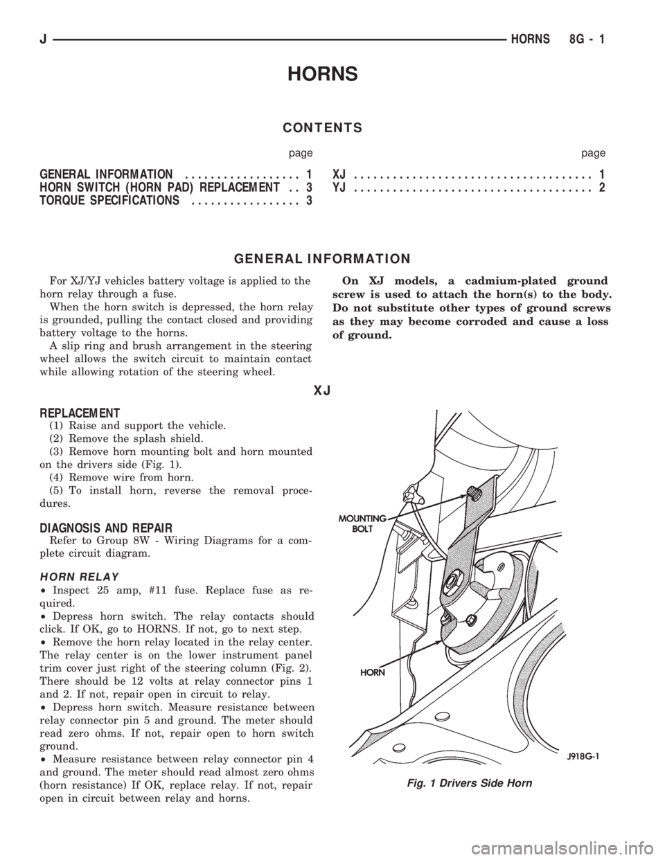
(3) Remove horn mounting bolt and horn mounted
on the drivers side (Fig. 1).
(4) Remove wire from horn.
(5) To install horn, reverse the removal proce-
dures.
DIAGNOSIS AND REPAIR
Refer to Group 8W - Wiring Diagrams for a com-
plete circuit diagram.
HORN RELAY
²Inspect 25 amp, #11 fuse. Replace fuse as re-
quired.
²Depress horn switch. The relay contacts should
click. If OK, go to HORNS. If not, go to next step.
²Remove the horn relay located in the relay center.
The relay center is on the lower instrument panel
trim cover just right of the steering column (Fig. 2).
There should be 12 volts at relay connector pins 1
and 2. If not, repair open in circuit to relay.
²Depress horn switch. Measure resistance between
relay connector pin 5 and ground. The meter should
read zero ohms. If not, repair open to horn switch
ground.
²Measure resistance between relay connector pin 4
and ground. The meter should read almost zero ohms
(horn resistance) If OK, replace relay. If not, repair
open in circuit between relay and horns.
Fig. 1 Drivers Side Horn
JHORNS 8G - 1
Page 390 of 1784
VEHICLE SPEED CONTROL SYSTEM
CONTENTS
page page
SERVICE PROCEDURES................... 9TEST PROCEDURES...................... 5
GENERAL INFORMATION
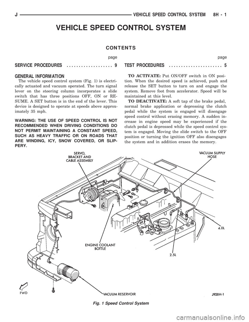
The vehicle speed control system (Fig. 1) is electri-
cally actuated and vacuum operated. The turn signal
lever on the steering column incorporates a slide
switch that has three positions OFF, ON or RE-
SUME. A SET button is in the end of the lever. This
device is designed to operate at speeds above approx-
imately 35 mph.
WARNING: THE USE OF SPEED CONTROL IS NOT
RECOMMENDED WHEN DRIVING CONDITIONS DO
NOT PERMIT MAINTAINING A CONSTANT SPEED,
SUCH AS HEAVY TRAFFIC OR ON ROADS THAT
ARE WINDING, ICY, SNOW COVERED, OR SLIP-
PERY.TO ACTIVATE:Put ON/OFF switch in ON posi-
tion. When the desired speed is achieved, push and
release the SET button to turn on and engage the
system. Remove foot from accelerator. Speed will be
maintained at this level.
TO DEACTIVATE:A soft tap of the brake pedal,
normal brake application or depressing the clutch
pedal while the system is engaged will disengage
speed control without erasing memory. A sudden in-
crease in engine speed may be experienced if the
clutch pedal is depressed while the speed control sys-
tem is engaged. Moving the slide switch to the OFF
position or turning the ignition OFF also disengages
the system and in addition erases the memory.
Fig. 1 Speed Control System
JVEHICLE SPEED CONTROL SYSTEM 8H - 1
Page 396 of 1784
perform the speed control switch test. If switch is not
at fault, then check main harness and repair as nec-
essary.
(8) Using an ohmmeter, connect one lead to a good
body ground and touch other lead to terminal in cav-
ity number 29. With brake pedal released, meter
should show continuity. When pedal is depressed,
meter should show open circuit.
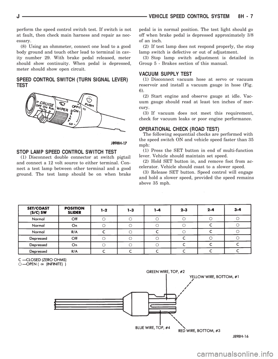
SPEED CONTROL SWITCH (TURN SIGNAL LEVER)
TEST
STOP LAMP SPEED CONTROL SWITCH TEST
(1) Disconnect double connector at switch pigtail
and connect a 12 volt source to either terminal. Con-
nect a test lamp between other terminal and a good
ground. The test lamp should be on when brakepedal is in normal position. The test light should go
off when brake pedal is depressed approximately 3/8
of an inch.
(2) If test lamp does not respond properly, the stop
lamp switch is defective or out of adjustment.
(3) Stop lamp switch adjustment is detailed in
Group 5 - Brakes section of this manual.
VACUUM SUPPLY TEST
(1) Disconnect vacuum hose at servo or vacuum
reservoir and install a vacuum gauge in hose (Fig.
6).
(2) Start engine and observe gauge at idle. Vac-
uum gauge should read at least ten inches of mer-
cury.
(3) If vacuum does not meet this requirement,
check for vacuum leaks or poor engine performance.
OPERATIONAL CHECK (ROAD TEST)
The following sequential checks are performed with
the speed switch ON and vehicle speed faster than 35
mph:
(1) Press the SET button in end of multi-function
lever. Vehicle should maintain set speed.
(2) Hold SET button in, and remove foot from ac-
celerator. Vehicle should coast to a slower speed.
(3) Release SET button. Speed control will engage
and hold a slower speed, provided the speed remains
above 35 mph.
JVEHICLE SPEED CONTROL SYSTEM 8H - 7
Page 408 of 1784
WINDSHIELD WIPERS
CONTENTS
page page
WIPER CONTROL SWITCH REPLACEMENT . . 15
WIPER SWITCH TESTING................ 19XJ .................................... 1
YJ .................................... 8
XJ
INDEX
page page
Diagnosing Rear Wiper..................... 6
Diagnosing Rear Wiper Washer.............. 6
Diagnosing Windshield Washer (Intermittent)..... 5
Diagnosing Windshield Washer (Non-Intermittent) . 4
Diagnosing Windshield Wipers............... 11
Front Wipers/Washers...................... 1
Intermittent Wiper Module................... 5
Liftgate Wiper............................ 5Liftgate Wiper Switch Replacement............ 6
Rear Wiper/Washer Switch Testing............ 7
Torque Specifications XJ.................... 7
Washer Pump Replacement................. 6
Washer Pump ReplacementÐLeft Hand Drive.... 2
Washer Pump ReplacementÐRight Hand Drive . . 3
Windshield Wiper Motor.................... 2
FRONT WIPERS/WASHERS
GENERAL
Two-speed electric windshield wipers and electric
washers are standard equipment. An optional inter-
mittent wiper system provides a pause between wipe
cycles for use during conditions of very light precipi-
tation.
The windshield wipers can be operated with the
windshield wiper switch only when the ignition
switch is in the ON or ACCESSORY position. A cir-
cuit breaker located in the fuse block protects the cir-
cuitry of the wiper system.
WIPERS
The standard windshield wiper circuit contains
three components; wiper/washer switch, motor, and
front washer pump. Both standard and intermittent
circuits are the same, except that the intermittent
circuit requires a module and delay resistance in the
wiper switch. Both circuits receive battery feed from,
and are protected by a 5.5 amp circuit breaker.
In the standard wiper circuit, the switch connects
the motor directly to battery feed for low and high
speed operation. In the intermittent circuit, the
switch supplies battery feed to the intermittent wiper
module, which then supplies the motor. In the delay
position, the module is connected with the variable
resistor in the wiper switch. The value of the resis-tance is used by the module to charge a capacitor,
which triggers the amount of delay between wipes.
The wiper motor has an arrangement of brushes
providing the two wiper speeds. When the wipers are
turned off, the park switch maintains current to the
motor until the wipers reach the park position on the
windshield.
The park arm in the motor assembly is connected
to the park switch and is driven by the motor. When
the wiper switch is turned off, current flows through
the contact and the module to the motor until the
wipers reach the park position.
CAUTION: The wiper arms and blades must not be
moved manually from side to side or damage may
result.
WASHERS
With the washer switch ON, current flows through
the washer pump to ground. The front washer pump
runs as long as the driver holds the switch ON. On
standard wipers, the washer switch automatically
moves the wiper switch to LO when the washer is
turned on. On intermittent wipers, the wiper module
runs the wiper motor on LO. Turning the switch to
OFF stops the wipers.
If the washer knob is depressed while the wiper
switch is in the OFF position, the wiper control will
operate for approximately 3 wipes and automatically
turn OFF.
JWINDSHIELD WIPERS 8K - 1
Page 415 of 1784
YJ
INDEX
page page
Diagnosing Windshield Wipers............... 11
Diagnosing Intermittent Windshield Washer..... 12
Diagnosing Non-Intermittent Windshield Washer . 12
Diagnosing Rear Wiper/Washer.............. 14
Front Wiper Arm and Pivot Assembly Replacement . 9
Front Wiper Arm Replacement............... 8
Front Wiper Blade Replacement.............. 8
Front Wiper Motor........................ 10Front Wipers/Washers General Information...... 8
Rear Washer Pump Replacement............ 13
Rear Wiper Arm Replacement............... 12
Rear Wiper Motor Replacement.............. 13
Rear Wiper Switch Replacement............. 13
Rear Wiper/Washer Switch Testing........... 14
Washer Nozzle Replacement................ 13
Washer Pump Replacement................ 11
FRONT WIPERS/WASHERS GENERAL
INFORMATION
The non-intermittent windshield wiper circuit con-
tains three components; control switch, motor and
washer pump. The intermittent circuit contains the
same components and a wiper module that provides
the delay function. Both circuits receive battery feed
from and are protected by a 5.3 amp circuit breaker.
In the non-intermittent wiper circuit, the switch
connects the motor directly to ignition feed for low
and high speed operation. In the intermittent circuit,
the switch supplies ignition feed to the delay module,
which then supplies the motor. In the delay position,
the module is connected with the variable resistor in
the wiper switch. The value of the resistance is used
by the solid state module to charge a capacitor,
which triggers the amount of delay between wipes.
The wiper motor has an arrangement of brushes
providing the two wiper speeds. When the wipers are
turned off, the park switch maintains current to the
motor until the wipers reach the park position on the
windshield.
The washer pump receives ignition feed either di-
rectly from the wiper switch or from the intermittent
module. In either case the electric motor will drive
the washer pump.
The wiper motor is mounted on the lower left cor-
ner of the windshield.
FRONT WIPER BLADE REPLACEMENT
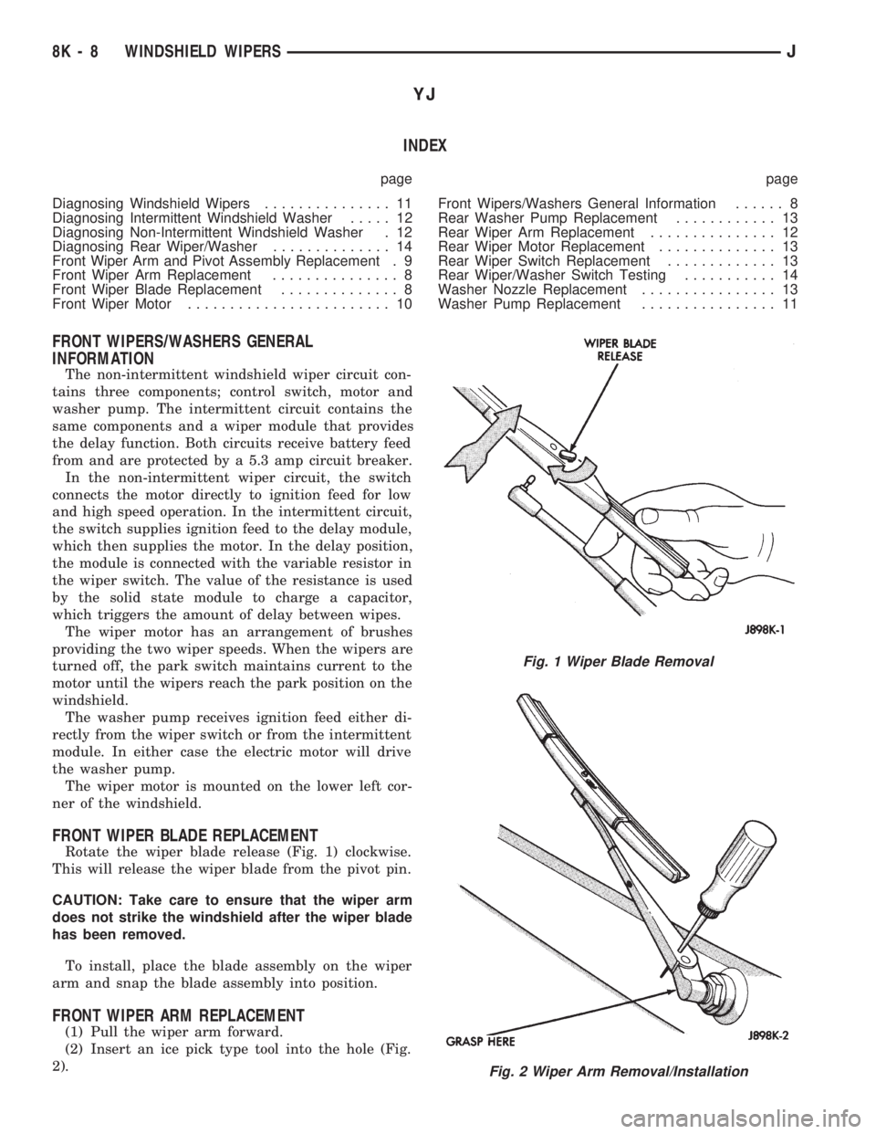
Rotate the wiper blade release (Fig. 1) clockwise.
This will release the wiper blade from the pivot pin.
CAUTION: Take care to ensure that the wiper arm
does not strike the windshield after the wiper blade
has been removed.
To install, place the blade assembly on the wiper
arm and snap the blade assembly into position.
FRONT WIPER ARM REPLACEMENT
(1) Pull the wiper arm forward.
(2) Insert an ice pick type tool into the hole (Fig.
2).
Fig. 1 Wiper Blade Removal
Fig. 2 Wiper Arm Removal/Installation
8K - 8 WINDSHIELD WIPERSJ
Page 472 of 1784
POWER WINDOWS
CONTENTS
page page
DESCRIPTION........................... 1
DIAGNOSIS (Figs. 1 and 2)............... 1SWITCH TESTING....................... 5
WINDOW REGULATOR REPLACEMENT...... 9
DESCRIPTION
All XJ vehicles, equipped with power windows,
have a cable driven window regulator system. A per-
manent magnet motor moves each power window.
Each motor raises or lowers the glass when voltage
is supplied to the motor. The direction the motor
turns depends on the polarity of the supply voltage.
The control switches control the supply voltage polar-
ity.
With the ignition switch in the ON position voltage
from the 60 amp fuse in the Power Distribution Cen-
ter is applied through the power window circuit
breaker. Power then goes to the master switch termi-
nal BY and to the passenger's window switches.
When the driver's window switch is moved UP, the
contacts close a current path to:
²terminal DV
²driver's side front window motor
²terminal CV
²the DOWN contact of the driver's side front win-
dow to ground.
The motor then moves the glass up.
Current flows in a similar way when the UP con-
tact in one of the passenger's window switches is
closed. Current flow through the passenger's window
motors must go through the driver's and the passen-
ger's window switches before it reaches ground.
Each motor is protected by a built-in circuit
breaker. If a window switch is held on too long with
the window obstructed or after the window is fully
up or down, the circuit breaker opens the circuit. The
circuit breaker resets automatically as it cools. Do
not allow frequent or consecutive resetting of the cir-
cuit breaker to continue.
DIAGNOSIS (Figs. 1 and 2)
For information concerning wiring or connectors,
refer to Group 8W - Wiring Diagrams.
NO WINDOWS OPERATE
²Measure voltage at power window feed connector
at fuse panel. Meter should read battery voltage. If
not, replace 60 amp fuse in Power Distribution Cen-
ter.
²Turn ignition switch to OFF and measure resis-
tance from side of cigar lighter socket to ground.
Meter should read zero ohms. If not, repair open to
ground.
²Remove master door lock/power window switch as-
sembly mounting screws. Measure resistance at BLK
wire (terminal DX) at driver's side switch. Meter
should read zero ohms. If not, repair open to ground
splice of instrument panel harness.
²Turn ignition switch to ON and measure voltage
at terminal BY at driver's side switch. Meter should
read battery voltage. If not, repair open to circuit
breaker.
²Operate window switch. If the windows move up
and down go to Switch Testing.
²Perform Switch Test Driver's Door. If switch
passes test, replace defective motors.
ONE WINDOW OPERATES
Remove door panel of inoperative window,
probe harness side of unplugged motor connec-
tor.
²Measure voltage at terminal A of connector, hold-
ing switch in the DOWN position. Meter should read
battery voltage. If not, repair open back to master
switch. If additional switch is in circuit (not driver's
side motor), refer to Switch Testing.
²Measure resistance at terminal B of connector,
holding switch in the DOWN position. Meter should
read zero ohms. Caution, maintain DOWN position
while meter lead is attached. If not, repair open back
to master switch. If additional switch is in circuit
(not driver's side motor), refer to Switch Testing. If
both tests are OK, replace regulator.
JPOWER WINDOWS 8S - 1