1994 JEEP CHEROKEE lamps
[x] Cancel search: lampsPage 428 of 1784
LAMPS
CONTENTS
page page
EXTERIOR LAMPS....................... 1
INTERIOR LAMPS...................... 19SPECIFICATIONS....................... 23
EXTERIOR LAMPS
INDEX
page page
Back-up/Rear Turn Signal/Tail Lamp Bulb
Replacement........................... 9
Center High Mounted Stop Lamp (CHMSL)ÐXJ . 10
Center High Mounted Stop Lamp (CHMSL)ÐYJ . 11
Daytime Running Lights (Canada Only)........ 16
DRL Module Replacement.................. 16
Fog Lamp Beam Adjustment................ 12
Fog Lamp Bulb/Element Replacement......... 13
Fog Lamp Replacement................... 15
Fog Lamp Service Information............... 12
Fog Lamp Switch Replacement.............. 14
Fog Lamp Trouble Diagnosis................ 12
Front Park/Turn Signal Lamp Bulb Replacement . . 8
Headlamp Beam Adjustment................. 3
Headlamp Bulb Replacement................ 3
Headlamp Delay Function Trouble DiagnosisÐXJ
Vehicles.............................. 16Headlamp Delay Module ReplacementÐXJ
Vehicles.............................. 16
Headlamp Dimmer Switch Replacement........ 6
Headlamp Switch Replacement............... 4
Headlamp Trouble DiagnosisÐXJ Vehicles...... 1
Headlamp Trouble DiagnosisÐYJ Vehicles...... 2
License Plate Lamp....................... 10
Sentinel Headlamp Delay ModuleÐXJ Vehicles . . 15
Service Information........................ 1
Side Marker Lamp Bulb Replacement.......... 7
Switch Tests............................. 2
Underhood Lamp Bulb Replacement.......... 18
Underhood Lamp Replacement.............. 18
Underhood Lamp Service Information......... 17
SERVICE INFORMATION
Exterior lamp circuits are comprised of the head-
lamp circuit, fog lamp circuit, and tail/side marker/
park lamp circuit. Battery voltage is controlled by
both the headlamp ON/OFF switch and headlamp
dimmer switch.
The dimmer switch functions as a fog lamp switch.
Voltage is applied to the fog lamp switch only when
the dimmer switch is in the low beam position.
HEADLAMP TROUBLE DIAGNOSISÐXJ VEHICLES
LOW AND HIGH BEAM INOPERATIVE BOTH
HEADLAMPS
(1) Place the headlamp switch in the ON position.
(2) Test the 40 amp fuse for continuity. If bad, re-
place fuse.
(3) Insert the test probe into terminal 5 of the
front lamp wire harness connector. Measure the re-
sistance from terminal 5 to body ground. The ohm-
meter should indicate zero ohms. If not OK, repair
the open circuit in the harness to body ground.(4) Disconnect the front lamp wire connector. Mea-
sure resistance between connector terminals 5 and 2.
Next measure between terminal 5 and 7. The ohm-
meter should indicate zero ohms for both measure-
ments. If not OK, replace the headlamp bulbs.
(5) Measure the voltage between the dimmer
switch wire connector terminal 2 and body ground.
The voltmeter should indicate battery voltage. If not
OK, continue with the next step.
The dimmer switch is integral with the turn
signal and is located on the steering column.
The dimmer switch switches the headlamp beam
when the turn signal lever is pulled rearward.
(6) Disconnect the dimmer switch wire connector
and place the headlamp switch in the OFF position.
Measure the resistance from terminal 2 to vehicle
body ground. The ohmmeter should indicate infinite
resistance. If OK, replace the headlamp switch and
continue with the next step. If not OK, repair the
short circuit in the wire harness that leads to termi-
nal 2.
JLAMPS 8L - 1
Page 429 of 1784
(7) Measure the resistance from the dimmer switch
wire harness connector terminal 1 to vehicle body
ground. The ohmmeter should indicate zero ohms. If
OK, continue with the next step. If not OK, repair
the short circuit in the wire harness that leads to
terminal 1.
(8) Measure the resistance from the dimmer switch
wire harness connector terminal 3 to vehicle body
ground. The ohmmeter should indicate zero ohms. If
OK, test the dimmer switch. Replace, if defective.
Connect the wire harness connector to the dimmer
switch. If not defective, repair the short circuit in the
wire harness that leads to terminal 3.
LOW OR HIGH BEAM INOPERATIVE BOTH
HEADLAMPS
(1) Place the headlamp switch in the OFF position.
Disconnect the dimmer switch wire harness connec-
tor.
(2) Measure the resistance from the dimmer switch
connector terminal 1 to body ground. The ohmmeter
should indicate zero ohms. If not OK, repair the open
circuit in the wire harness that leads to the head-
lamp bulbs.
(3) Measure the resistance from the dimmer switch
connector terminal 3 to vehicle body ground. The
ohmmeter should indicate zero ohms. If OK, replace
the dimmer switch. If not OK, repair the open circuit
in the wire harness that leads to headlamp bulbs.
HEADLAMP TROUBLE DIAGNOSISÐYJ VEHICLES
(1) Place the headlamp switch in the ON position.
(2) Place the headlamp dimmer switch in the
HIGH or LOW position.
(3) Disconnect the wire harness connectors from
the headlamp bulbs.
(4) If applicable, measure voltage between each
headlamp bulb wire connector terminal B and vehi-
cle body ground. The voltmeter should indicate bat-
tery voltage. If not OK, repair the open circuit in
wire harness between connector and dimmer switch.
(5) If applicable, measure the voltage between each
headlamp bulb connector terminal C and body
ground. The voltmeter should indicate battery volt-
age. If not OK, repair the open circuit in the wire
harness between the connector and the dimmer
switch.
(6) Measure the resistance from each headlamp
bulb connector terminal A to body ground. The ohm-
meter should indicate zero ohms. If not OK, repair
the open circuit in the wire harness between the con-
nectors and vehicle body ground.
SWITCH TESTS
HEADLAMPÐALL VEHICLES
(1) Refer to the applicable wiring diagram for ter-
minal reference.(2) Place the headlamp switch in the ON position.
(3) Measure the voltage between the headlamp
switch connector voltage supply terminal and vehicle
body ground. The voltmeter should indicate battery
voltage. If not OK, repair the open circuit in the wire
harness between the fuse and the switch connector
terminal.
(4) Measure the voltage between the headlamp
switch connector battery voltage OUT terminal and
vehicle body ground. The voltmeter should indicate
battery voltage. If not OK, replace the headlamp
switch.
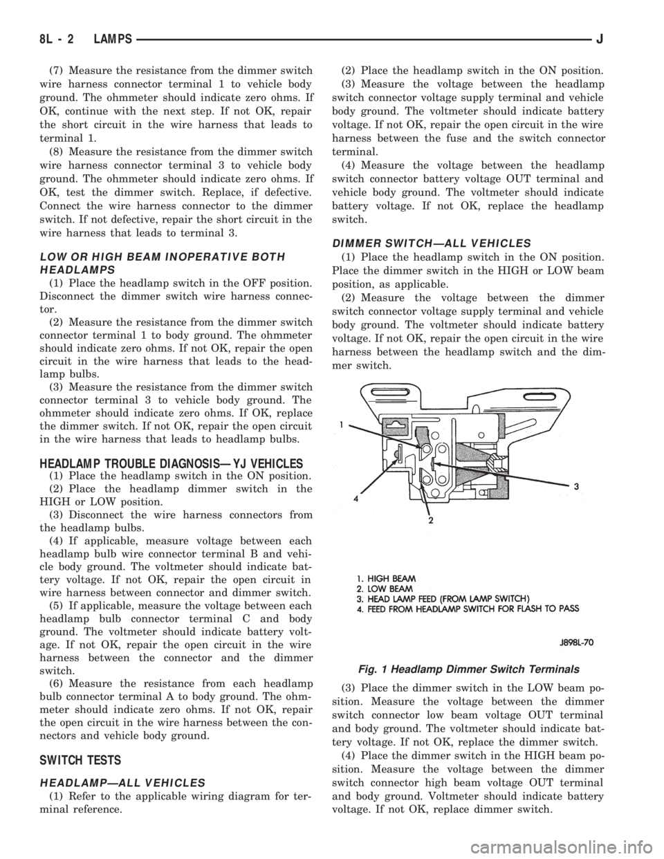
DIMMER SWITCHÐALL VEHICLES
(1) Place the headlamp switch in the ON position.
Place the dimmer switch in the HIGH or LOW beam
position, as applicable.
(2) Measure the voltage between the dimmer
switch connector voltage supply terminal and vehicle
body ground. The voltmeter should indicate battery
voltage. If not OK, repair the open circuit in the wire
harness between the headlamp switch and the dim-
mer switch.
(3) Place the dimmer switch in the LOW beam po-
sition. Measure the voltage between the dimmer
switch connector low beam voltage OUT terminal
and body ground. The voltmeter should indicate bat-
tery voltage. If not OK, replace the dimmer switch.
(4) Place the dimmer switch in the HIGH beam po-
sition. Measure the voltage between the dimmer
switch connector high beam voltage OUT terminal
and body ground. Voltmeter should indicate battery
voltage. If not OK, replace dimmer switch.
Fig. 1 Headlamp Dimmer Switch Terminals
8L - 2 LAMPSJ
Page 430 of 1784
HEADLAMP BULB REPLACEMENT
REMOVAL
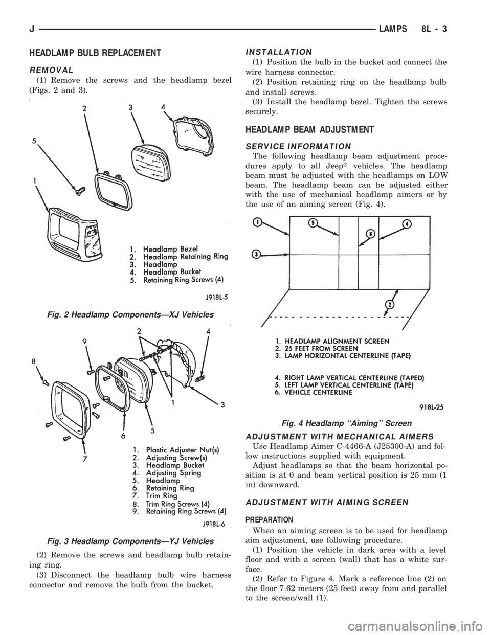
(1) Remove the screws and the headlamp bezel
(Figs. 2 and 3).
(2) Remove the screws and headlamp bulb retain-
ing ring.
(3) Disconnect the headlamp bulb wire harness
connector and remove the bulb from the bucket.
INSTALLATION
(1) Position the bulb in the bucket and connect the
wire harness connector.
(2) Position retaining ring on the headlamp bulb
and install screws.
(3) Install the headlamp bezel. Tighten the screws
securely.
HEADLAMP BEAM ADJUSTMENT
SERVICE INFORMATION
The following headlamp beam adjustment proce-
dures apply to all Jeeptvehicles. The headlamp
beam must be adjusted with the headlamps on LOW
beam. The headlamp beam can be adjusted either
with the use of mechanical headlamp aimers or by
the use of an aiming screen (Fig. 4).
ADJUSTMENT WITH MECHANICAL AIMERS
Use Headlamp Aimer C-4466-A (J25300-A) and fol-
low instructions supplied with equipment.
Adjust headlamps so that the beam horizontal po-
sition is at 0 and beam vertical position is 25 mm (1
in) downward.
ADJUSTMENT WITH AIMING SCREEN
PREPARATION
When an aiming screen is to be used for headlamp
aim adjustment, use following procedure.
(1) Position the vehicle in dark area with a level
floor and with a screen (wall) that has a white sur-
face.
(2) Refer to Figure 4. Mark a reference line (2) on
the floor 7.62 meters (25 feet) away from and parallel
to the screen/wall (1).
Fig. 2 Headlamp ComponentsÐXJ Vehicles
Fig. 3 Headlamp ComponentsÐYJ Vehicles
Fig. 4 Headlamp ``Aiming'' Screen
JLAMPS 8L - 3
Page 431 of 1784
(3) Move vehicle with the headlamps located di-
rectly above the 7.62-meters (25-feet) reference line.
(4) Equalize all the tire pressures.
(5) Rock vehicle from side to side to stabilize the
springs and shock absorbers.
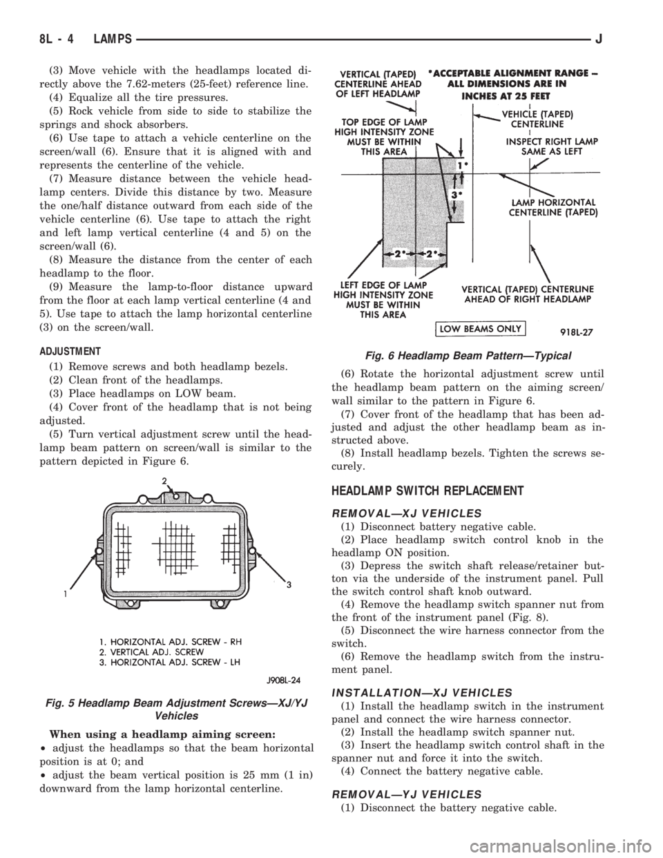
(6) Use tape to attach a vehicle centerline on the
screen/wall (6). Ensure that it is aligned with and
represents the centerline of the vehicle.
(7) Measure distance between the vehicle head-
lamp centers. Divide this distance by two. Measure
the one/half distance outward from each side of the
vehicle centerline (6). Use tape to attach the right
and left lamp vertical centerline (4 and 5) on the
screen/wall (6).
(8) Measure the distance from the center of each
headlamp to the floor.
(9) Measure the lamp-to-floor distance upward
from the floor at each lamp vertical centerline (4 and
5). Use tape to attach the lamp horizontal centerline
(3) on the screen/wall.
ADJUSTMENT
(1) Remove screws and both headlamp bezels.
(2) Clean front of the headlamps.
(3) Place headlamps on LOW beam.
(4) Cover front of the headlamp that is not being
adjusted.
(5) Turn vertical adjustment screw until the head-
lamp beam pattern on screen/wall is similar to the
pattern depicted in Figure 6.
When using a headlamp aiming screen:
²adjust the headlamps so that the beam horizontal
position is at 0; and
²adjust the beam vertical position is 25 mm (1 in)
downward from the lamp horizontal centerline.(6) Rotate the horizontal adjustment screw until
the headlamp beam pattern on the aiming screen/
wall similar to the pattern in Figure 6.
(7) Cover front of the headlamp that has been ad-
justed and adjust the other headlamp beam as in-
structed above.
(8) Install headlamp bezels. Tighten the screws se-
curely.
HEADLAMP SWITCH REPLACEMENT
REMOVALÐXJ VEHICLES
(1) Disconnect battery negative cable.
(2) Place headlamp switch control knob in the
headlamp ON position.
(3) Depress the switch shaft release/retainer but-
ton via the underside of the instrument panel. Pull
the switch control shaft knob outward.
(4) Remove the headlamp switch spanner nut from
the front of the instrument panel (Fig. 8).
(5) Disconnect the wire harness connector from the
switch.
(6) Remove the headlamp switch from the instru-
ment panel.
INSTALLATIONÐXJ VEHICLES
(1) Install the headlamp switch in the instrument
panel and connect the wire harness connector.
(2) Install the headlamp switch spanner nut.
(3) Insert the headlamp switch control shaft in the
spanner nut and force it into the switch.
(4) Connect the battery negative cable.
REMOVALÐYJ VEHICLES
(1) Disconnect the battery negative cable.
Fig. 5 Headlamp Beam Adjustment ScrewsÐXJ/YJ
Vehicles
Fig. 6 Headlamp Beam PatternÐTypical
8L - 4 LAMPSJ
Page 432 of 1784
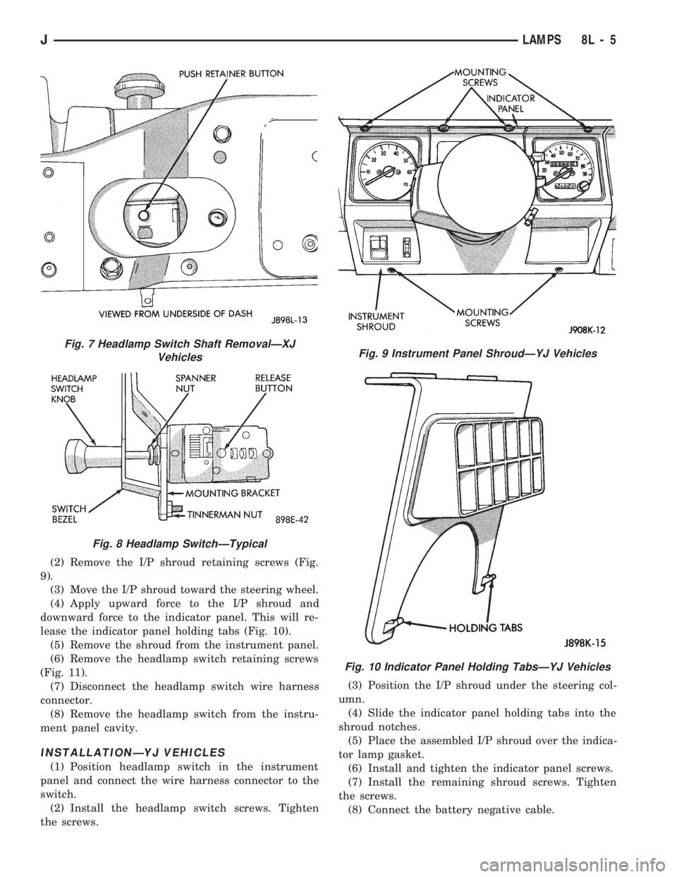
(2) Remove the I/P shroud retaining screws (Fig.
9).
(3) Move the I/P shroud toward the steering wheel.
(4) Apply upward force to the I/P shroud and
downward force to the indicator panel. This will re-
lease the indicator panel holding tabs (Fig. 10).
(5) Remove the shroud from the instrument panel.
(6) Remove the headlamp switch retaining screws
(Fig. 11).
(7) Disconnect the headlamp switch wire harness
connector.
(8) Remove the headlamp switch from the instru-
ment panel cavity.
INSTALLATIONÐYJ VEHICLES
(1) Position headlamp switch in the instrument
panel and connect the wire harness connector to the
switch.
(2) Install the headlamp switch screws. Tighten
the screws.(3) Position the I/P shroud under the steering col-
umn.
(4) Slide the indicator panel holding tabs into the
shroud notches.
(5) Place the assembled I/P shroud over the indica-
tor lamp gasket.
(6) Install and tighten the indicator panel screws.
(7) Install the remaining shroud screws. Tighten
the screws.
(8) Connect the battery negative cable.
Fig. 7 Headlamp Switch Shaft RemovalÐXJ
Vehicles
Fig. 8 Headlamp SwitchÐTypical
Fig. 9 Instrument Panel ShroudÐYJ Vehicles
Fig. 10 Indicator Panel Holding TabsÐYJ Vehicles
JLAMPS 8L - 5
Page 433 of 1784
HEADLAMP DIMMER SWITCH REPLACEMENT
REMOVAL
(1) Disconnect battery negative cable.
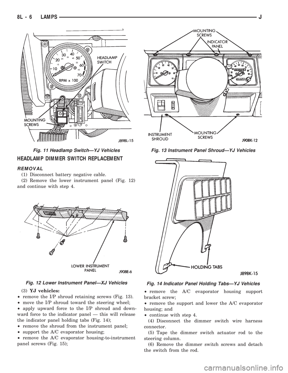
(2) Remove the lower instrument panel (Fig. 12)
and continue with step 4.
(3)YJ vehicles:
²remove the I/P shroud retaining screws (Fig. 13).
²move the I/P shroud toward the steering wheel;
²apply upward force to the I/P shroud and down-
ward force to the indicator panel Ð this will release
the indicator panel holding tabs (Fig. 14);
²remove the shroud from the instrument panel;
²support the A/C evaporator housing;
²remove the A/C evaporator housing-to-instrument
panel screws (Fig. 15);²remove the A/C evaporator housing support
bracket screw;
²remove the support and lower the A/C evaporator
housing; and
²continue with step 4.
(4) Disconnect the dimmer switch wire harness
connector.
(5) Tape the dimmer switch actuator rod to the
steering column.
(6) Remove the dimmer switch screws and detach
the switch from the rod.
Fig. 11 Headlamp SwitchÐYJ Vehicles
Fig. 12 Lower Instrument PanelÐXJ Vehicles
Fig. 13 Instrument Panel ShroudÐYJ Vehicles
Fig. 14 Indicator Panel Holding TabsÐYJ Vehicles
8L - 6 LAMPSJ
Page 434 of 1784
INSTALLATION
(1) Force the dimmer switch onto the actuator rod
and install screws.DO NOT tighten the retaining
screws at this time.
(2) Remove the tape attaching the actuator rod to
the steering column.
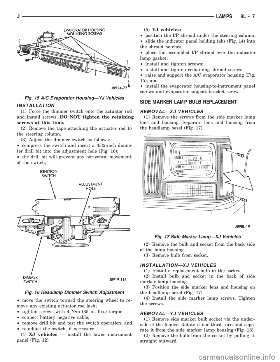
(3) Adjust the dimmer switch as follows:
²compress the switch and insert a 3/32-inch diame-
ter drill bit into the adjustment hole (Fig. 16);
²the drill bit will prevent any horizontal movement
of the switch;
²move the switch toward the steering wheel to re-
move any existing actuator rod lash;
²tighten screws with 4 Nzm (35 in. lbs.) torque.
²connect battery negative cable;
²remove drill bit and test the switch operation; and
²re-adjust the switch, if necessary.
(4)XJ vehiclesÐ install the lower instrument
panel (Fig. 12)(5)YJ vehicles:
²position the I/P shroud under the steering column;
²slide the indicator panel holding tabs (Fig. 14) into
the shroud notches;
²place the assembled I/P shroud over the indicator
lamp gasket;
²install and tighten screws;
²install and tighten remaining shroud screws;
²raise and support the A/C evaporator housing (Fig.
15); and
²install the evaporator housing-to-instrument panel
screws and evaporator support bracket screw.
SIDE MARKER LAMP BULB REPLACEMENT
REMOVALÐXJ VEHICLES
(1) Remove the screws from the side marker lamp
lens and housing. Separate lens and housing from
the headlamp bezel (Fig. 17).
(2) Remove the bulb and socket from the back side
of the lamp housing.
(3) Remove bulb from socket.
INSTALLATIONÐXJ VEHICLES
(1) Install a replacement bulb in the socket.
(2) Install bulb and socket in the back of side
marker lamp housing.
(3) Position the side marker lens and housing on
the headlamp bezel (Fig. 17).
(4) Install the side marker lamp screws. Tighten
the screws.
REMOVALÐYJ VEHICLES
(1) Remove side marker bulb socket via the under-
side of the fender. Rotate it one-third turn and sepa-
rate it from the side marker lamp housing (Fig. 18).
(2) Remove the bulb from the socket by pulling it
straight outward.
Fig. 15 A/C Evaporator HousingÐYJ Vehicles
Fig. 16 Headlamp Dimmer Switch Adjustment
Fig. 17 Side Marker LampÐXJ Vehicles
JLAMPS 8L - 7
Page 435 of 1784
INSTALLATIONÐYJ VEHICLES
(1) Install a replacement bulb in the socket.
(2) Install the bulb and socket in the side marker
lamp housing (Fig. 18).
FRONT PARK/TURN SIGNAL LAMP BULB
REPLACEMENT
REMOVALÐXJ VEHICLES
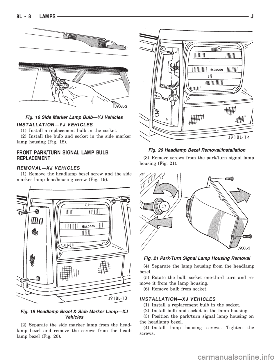
(1) Remove the headlamp bezel screw and the side
marker lamp lens/housing screw (Fig. 19).
(2) Separate the side marker lamp from the head-
lamp bezel and remove the screws from the head-
lamp bezel (Fig. 20).(3) Remove screws from the park/turn signal lamp
housing (Fig. 21).
(4) Separate the lamp housing from the headlamp
bezel.
(5) Rotate the bulb socket one-third turn and re-
move it from the lamp housing.
(6) Remove bulb from socket.
INSTALLATIONÐXJ VEHICLES
(1) Install a replacement bulb in the socket.
(2) Install bulb and socket in the lamp housing.
(3) Position the park/turn signal lamp housing on
the headlamp bezel.
(4) Install lamp housing screws. Tighten the
screws.
Fig. 18 Side Marker Lamp BulbÐYJ Vehicles
Fig. 19 Headlamp Bezel & Side Marker LampÐXJ
Vehicles
Fig. 20 Headlamp Bezel Removal/Installation
Fig. 21 Park/Turn Signal Lamp Housing Removal
8L - 8 LAMPSJ