1994 JEEP CHEROKEE lamps
[x] Cancel search: lampsPage 139 of 1784
MULTI-PORT FUEL INJECTION (MFI)ÐCOMPONENT REMOVAL/INSTALLATION
INDEX
page page
Accelerator Pedal and Throttle Cable......... 54
Air Cleaner Housing...................... 54
Air Conditioning (A/C) Clutch Relay........... 54
Air Filter............................... 54
Automatic Shut Down (ASD) Relay........... 54
Brake Switch............................ 54
Camshaft Position Sensor.................. 54
Crankshaft Position Sensor................. 55
Engine Coolant Temperature Sensor.......... 55
Fuel Filter.............................. 55
Fuel Injector............................ 55
Fuel Pump Module....................... 56
Fuel Pump Relay........................ 56
Fuel Rail Assembly....................... 56
Fuel System Pressure Release Procedure...... 56
Fuel Tank Pressure Relief/Rollover Valve...... 56
Fuel Tanks............................. 56Fuel Tubes/Lines/Hoses and Clamps.......... 56
Idle Air Control (IAC) Motor................. 56
Ignition Coil............................. 57
Intake Air Temperature Sensor.............. 54
Intake Manifold.......................... 57
Manifold Absolute Pressure (MAP) Sensor..... 57
Oxygen (O2S) Sensor..................... 57
Park Neutral Switch....................... 58
Power Steering Pressure SwitchÐ2.5L
Engine Only........................... 58
Powertrain Control Module (PCM)............ 58
Quick-Connect Fittings..................... 59
Throttle Body............................ 59
Throttle Position Sensor (TPS).............. 59
Torque Converter Clutch Relay.............. 60
Vehicle Speed Sensor..................... 60
ACCELERATOR PEDAL AND THROTTLE CABLE
Refer to the Accelerator Pedal and Throttle Cable
section of this group for removal/installation proce-
dures.
AIR CONDITIONING (A/C) CLUTCH RELAY
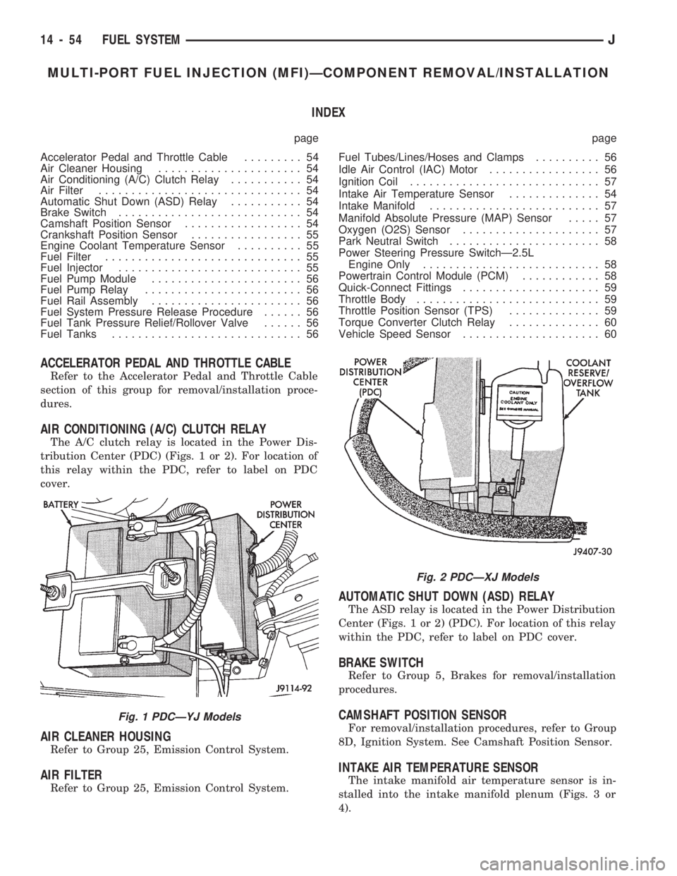
The A/C clutch relay is located in the Power Dis-
tribution Center (PDC) (Figs. 1 or 2). For location of
this relay within the PDC, refer to label on PDC
cover.
AIR CLEANER HOUSING
Refer to Group 25, Emission Control System.
AIR FILTER
Refer to Group 25, Emission Control System.
AUTOMATIC SHUT DOWN (ASD) RELAY
The ASD relay is located in the Power Distribution
Center (Figs. 1 or 2) (PDC). For location of this relay
within the PDC, refer to label on PDC cover.
BRAKE SWITCH
Refer to Group 5, Brakes for removal/installation
procedures.
CAMSHAFT POSITION SENSOR
For removal/installation procedures, refer to Group
8D, Ignition System. See Camshaft Position Sensor.
INTAKE AIR TEMPERATURE SENSOR
The intake manifold air temperature sensor is in-
stalled into the intake manifold plenum (Figs. 3 or
4).
Fig. 1 PDCÐYJ Models
Fig. 2 PDCÐXJ Models
14 - 54 FUEL SYSTEMJ
Page 141 of 1784
INSTALLATION
(1) Install the fuel injector(s) into the fuel rail as-
sembly and install retaining clip(s).
(2) Install fuel rail. Refer to Fuel Rail Installation
in this section.
(3) Start engine and check for fuel leaks.
FUEL PUMP MODULE
Refer to the Fuel Delivery System section of this
group for removal/installation procedures.
FUEL PUMP RELAY
The Fuel Pump relay is located in the Power Dis-
tribution Center (PDC) (Figs. 1 or 2). For location of
this relay within the PDC, refer to label on PDC
cover.
FUEL RAIL ASSEMBLY
REMOVAL
WARNING: THE FUEL SYSTEM IS UNDER CON-
STANT FUEL PRESSURE (EVEN WITH THE ENGINE
OFF) OF APPROXIMATELY 131-269 KPA (19-39
PSI). THIS PRESSURE MUST BE RELEASED BE-
FORE SERVICING THE FUEL RAIL.
(1) Remove fuel tank filler tube cap.
(2) Disconnect the negative battery cable from bat-
tery.
(3) Perform the Fuel System Pressure Release Pro-
cedure as described in the Fuel Delivery System sec-
tion of this Group.
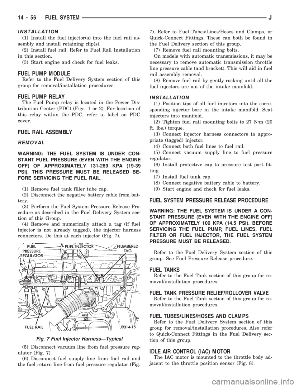
(4) Remove and numerically attach a tag (if fuel
injector is not already tagged), the injector harness
connectors. Do this at each injector (Fig. 7).
(5) Disconnect vacuum line from fuel pressure reg-
ulator (Fig. 7).
(6) Disconnect fuel supply line from fuel rail and
the fuel return line from fuel pressure regulator (Fig.7). Refer to Fuel Tubes/Lines/Hoses and Clamps, or
Quick-Connect Fittings. These can both be found in
the Fuel Delivery section of this group.
(7) Remove fuel rail mounting bolts.
On models with automatic transmissions, it may be
necessary to remove automatic transmission throttle
line pressure cable (and bracket). This will aid in fuel
rail assembly removal.
(8) Remove fuel rail by gently rocking until all the
fuel injectors are out of the intake manifold.
INSTALLATION
(1) Position tips of all fuel injectors into the corre-
sponding injector bore in the intake manifold. Seat
injectors into manifold.
(2) Tighten fuel rail mounting bolts to 27 Nzm (20
ft. lbs.) torque.
(3) Connect injector harness connectors to appro-
priate (tagged) injector.
(4) Connect both fuel lines to fuel rail.
(5) Connect vacuum supply line to fuel pressure
regulator.
(6) Install protective cap to pressure test port fit-
ting.
(7) Install fuel tank cap.
(8) Connect negative battery cable to battery.
(9) Start engine and check for fuel leaks.
FUEL SYSTEM PRESSURE RELEASE PROCEDURE
WARNING: THE FUEL SYSTEM IS UNDER A CON-
STANT PRESSURE (EVEN WITH THE ENGINE OFF)
OF APPROXIMATELY 100 KPA (14.5 PSI). BEFORE
SERVICING THE FUEL PUMP, FUEL LINES, FUEL
FILTER OR FUEL INJECTOR, THE FUEL SYSTEM
PRESSURE MUST BE RELEASED.
Refer to the Fuel Delivery System section of this
group. See Fuel Pressure Release procedure.
FUEL TANKS
Refer to the Fuel Tank section of this group for re-
moval/installation procedures.
FUEL TANK PRESSURE RELIEF/ROLLOVER VALVE
Refer to the Fuel Tank section of this group for re-
moval/installation procedures.
FUEL TUBES/LINES/HOSES AND CLAMPS
Refer to the Fuel Delivery System section of this
group for removal/installation procedures. Also refer
to Quick-Connect Fittings in the Fuel Delivery sec-
tion of this group.
IDLE AIR CONTROL (IAC) MOTOR
The IAC motor is mounted to the throttle body ad-
jacent to the throttle position sensor (Fig. 8).
Fig. 7 Fuel Injector HarnessÐTypical
14 - 56 FUEL SYSTEMJ
Page 181 of 1784
DRUM BRAKES
INDEX
page page
Brake Drum Refinishing.................... 37
Drum Brake Adjustment................... 35
Drum Brakeshoe Installation................ 34
Drum Brakeshoe Removal (Figs. 1 and 2)...... 34
Support Plate Replacement................. 37Wheel Cylinder Installation................. 37
Wheel Cylinder Overhaul (Figs. 8 and 9)....... 36
Wheel Cylinder Removal................... 36
Wheel Nut Tightening..................... 37
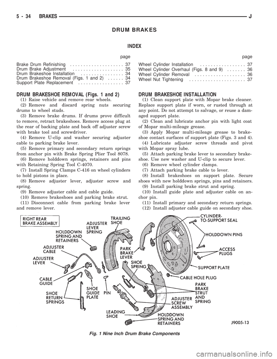
DRUM BRAKESHOE REMOVAL (Figs. 1 and 2)
(1) Raise vehicle and remove rear wheels.
(2) Remove and discard spring nuts securing
drums to wheel studs.
(3) Remove brake drums. If drums prove difficult
to remove, retract brakeshoes. Remove access plug at
the rear of backing plate and back off adjuster screw
with brake tool and screwdriver.
(4) Remove U-clip and washer securing adjuster
cable to parking brake lever.
(5) Remove primary and secondary return springs
from anchor pin with Brake Spring Plier Tool 8078.
(6) Remove holddown springs, retainers and pins
with Retaining Spring Tool C-4070.
(7) Install Spring Clamps C-416 on wheel cylinders
to hold pistons in place.
(8) Remove adjuster lever, adjuster screw and
spring.
(9) Remove adjuster cable and cable guide.
(10) Remove brakeshoes and parking brake strut.
(11) Disconnect cable from parking brake lever
and remove lever.
DRUM BRAKESHOE INSTALLATION
(1) Clean support plate with Mopar brake cleaner.
Replace support plate if worn, or rusted through at
any point. Do not attempt to salvage, or reuse a dam-
aged support plate.
(2) Clean and lubricate anchor pin with light coat
of Mopar multi-mileage grease.
(3) Apply Mopar multi-mileage grease to brake-
shoe contact surfaces of support plate (Figs. 3 and 4).
(4) Lubricate adjuster screw threads and pivot
with Mopar spray lube.
(5) Attach parking brake lever to secondary brake-
shoe. Use new washer and U-clip to secure lever.
(6) Remove wheel cylinder clamps.
(7) Attach parking brake cable to lever.
(8) Install brakeshoes on support plate. Secure
shoes with new holddown springs, pins and retainers.
(9) Install parking brake strut and spring.
(10) Install guide plate and adjuster cable on an-
chor pin.
(11) Install primary and secondary return springs.
(12) Install adjuster cable guide on secondary shoe.
Fig. 1 Nine Inch Drum Brake Components
5 - 34 BRAKESJ
Page 197 of 1784
(2) Raise vehicle.
(3) Disconnect sensor wires at rear axle connectors.
(4) Remove wheel and tire assembly.
(5) Remove brake drum.
(6) Remove clips securing sensor wires to brake
lines or rear axle and rear brake hose.
(7) Unseat sensor support plate grommet.
(8) Remove bolt attaching sensor to bracket and
remove sensor.
REAR WHEEL SENSOR INSTALLATION
(1) Insert sensor wire through support plate hole
and seat sensor grommet in support plate.
(2) Apply Mopar Lock N' Seal or Loctite 242 to
original sensor bolt. Use new bolt if original is worn
or damaged.
(3) Install sensor bolt finger tight only at this
time.
(4) Set sensor air gap as follows:
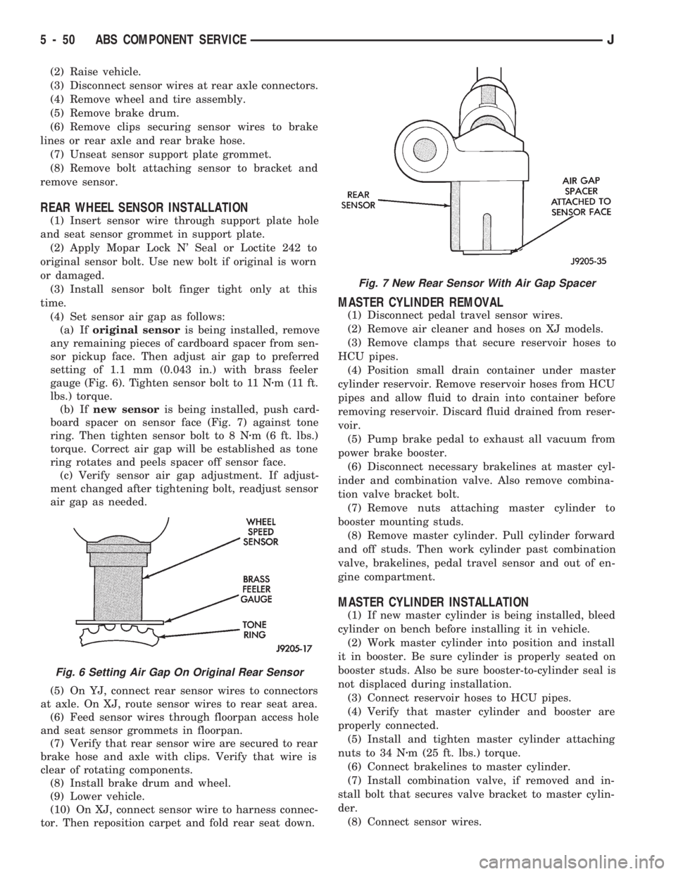
(a) Iforiginal sensoris being installed, remove
any remaining pieces of cardboard spacer from sen-
sor pickup face. Then adjust air gap to preferred
setting of 1.1 mm (0.043 in.) with brass feeler
gauge (Fig. 6). Tighten sensor bolt to 11 Nzm (11 ft.
lbs.) torque.
(b) Ifnew sensoris being installed, push card-
board spacer on sensor face (Fig. 7) against tone
ring. Then tighten sensor bolt to 8 Nzm (6 ft. lbs.)
torque. Correct air gap will be established as tone
ring rotates and peels spacer off sensor face.
(c) Verify sensor air gap adjustment. If adjust-
ment changed after tightening bolt, readjust sensor
air gap as needed.
(5) On YJ, connect rear sensor wires to connectors
at axle. On XJ, route sensor wires to rear seat area.
(6) Feed sensor wires through floorpan access hole
and seat sensor grommets in floorpan.
(7) Verify that rear sensor wire are secured to rear
brake hose and axle with clips. Verify that wire is
clear of rotating components.
(8) Install brake drum and wheel.
(9) Lower vehicle.
(10) On XJ, connect sensor wire to harness connec-
tor. Then reposition carpet and fold rear seat down.
MASTER CYLINDER REMOVAL
(1) Disconnect pedal travel sensor wires.
(2) Remove air cleaner and hoses on XJ models.
(3) Remove clamps that secure reservoir hoses to
HCU pipes.
(4) Position small drain container under master
cylinder reservoir. Remove reservoir hoses from HCU
pipes and allow fluid to drain into container before
removing reservoir. Discard fluid drained from reser-
voir.
(5) Pump brake pedal to exhaust all vacuum from
power brake booster.
(6) Disconnect necessary brakelines at master cyl-
inder and combination valve. Also remove combina-
tion valve bracket bolt.
(7) Remove nuts attaching master cylinder to
booster mounting studs.
(8) Remove master cylinder. Pull cylinder forward
and off studs. Then work cylinder past combination
valve, brakelines, pedal travel sensor and out of en-
gine compartment.
MASTER CYLINDER INSTALLATION
(1) If new master cylinder is being installed, bleed
cylinder on bench before installing it in vehicle.
(2) Work master cylinder into position and install
it in booster. Be sure cylinder is properly seated on
booster studs. Also be sure booster-to-cylinder seal is
not displaced during installation.
(3) Connect reservoir hoses to HCU pipes.
(4) Verify that master cylinder and booster are
properly connected.
(5) Install and tighten master cylinder attaching
nuts to 34 Nzm (25 ft. lbs.) torque.
(6) Connect brakelines to master cylinder.
(7) Install combination valve, if removed and in-
stall bolt that secures valve bracket to master cylin-
der.
(8) Connect sensor wires.
Fig. 6 Setting Air Gap On Original Rear Sensor
Fig. 7 New Rear Sensor With Air Gap Spacer
5 - 50 ABS COMPONENT SERVICEJ
Page 198 of 1784
(9) Fill reservoir and bleed brakes. Refer to proce-
dure in this section.
(10) Install air cleaner and hoses.
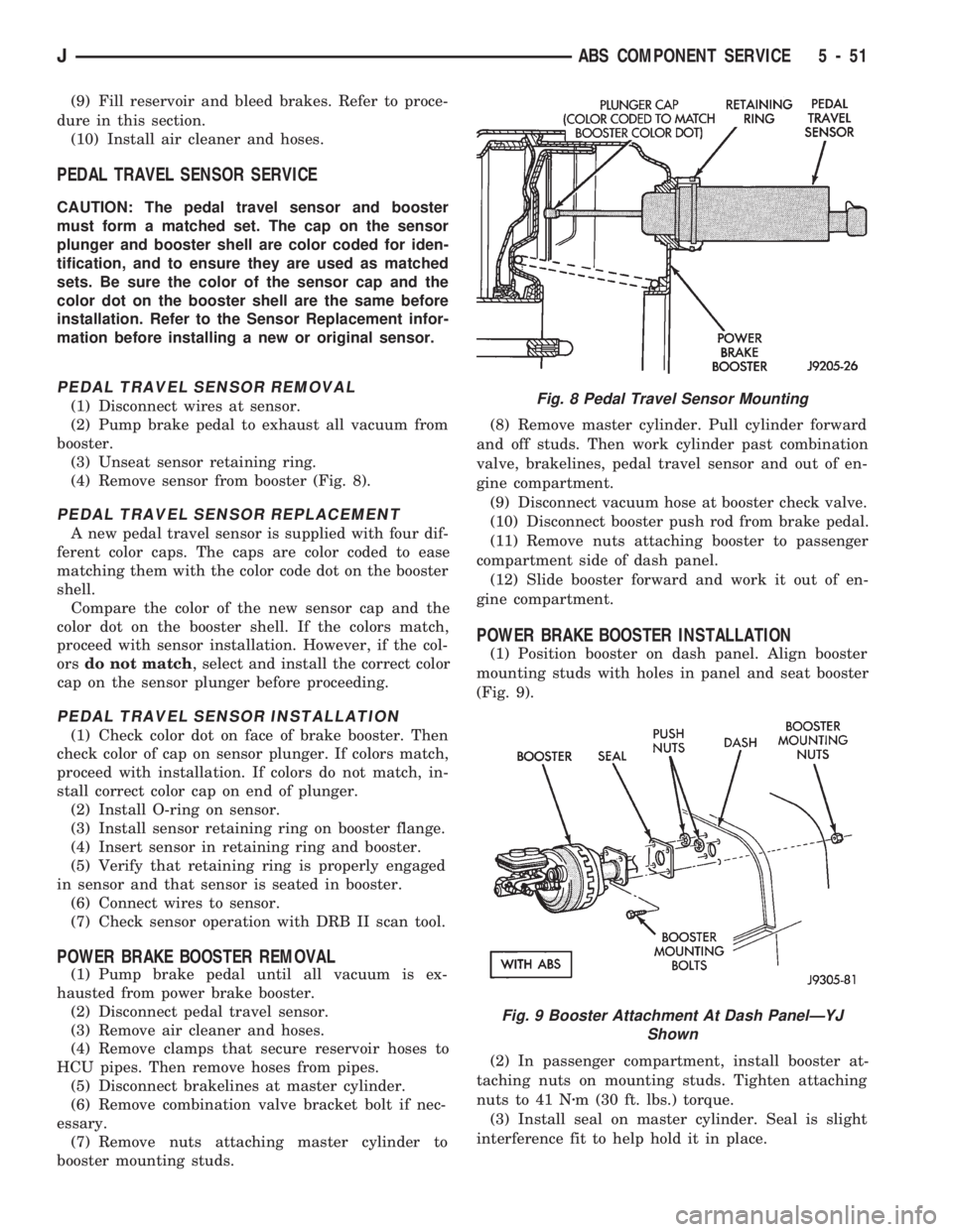
PEDAL TRAVEL SENSOR SERVICE
CAUTION: The pedal travel sensor and booster
must form a matched set. The cap on the sensor
plunger and booster shell are color coded for iden-
tification, and to ensure they are used as matched
sets. Be sure the color of the sensor cap and the
color dot on the booster shell are the same before
installation. Refer to the Sensor Replacement infor-
mation before installing a new or original sensor.
PEDAL TRAVEL SENSOR REMOVAL
(1) Disconnect wires at sensor.
(2) Pump brake pedal to exhaust all vacuum from
booster.
(3) Unseat sensor retaining ring.
(4) Remove sensor from booster (Fig. 8).
PEDAL TRAVEL SENSOR REPLACEMENT
A new pedal travel sensor is supplied with four dif-
ferent color caps. The caps are color coded to ease
matching them with the color code dot on the booster
shell.
Compare the color of the new sensor cap and the
color dot on the booster shell. If the colors match,
proceed with sensor installation. However, if the col-
orsdo not match, select and install the correct color
cap on the sensor plunger before proceeding.
PEDAL TRAVEL SENSOR INSTALLATION
(1) Check color dot on face of brake booster. Then
check color of cap on sensor plunger. If colors match,
proceed with installation. If colors do not match, in-
stall correct color cap on end of plunger.
(2) Install O-ring on sensor.
(3) Install sensor retaining ring on booster flange.
(4) Insert sensor in retaining ring and booster.
(5) Verify that retaining ring is properly engaged
in sensor and that sensor is seated in booster.
(6) Connect wires to sensor.
(7) Check sensor operation with DRB II scan tool.
POWER BRAKE BOOSTER REMOVAL
(1) Pump brake pedal until all vacuum is ex-
hausted from power brake booster.
(2) Disconnect pedal travel sensor.
(3) Remove air cleaner and hoses.
(4) Remove clamps that secure reservoir hoses to
HCU pipes. Then remove hoses from pipes.
(5) Disconnect brakelines at master cylinder.
(6) Remove combination valve bracket bolt if nec-
essary.
(7) Remove nuts attaching master cylinder to
booster mounting studs.(8) Remove master cylinder. Pull cylinder forward
and off studs. Then work cylinder past combination
valve, brakelines, pedal travel sensor and out of en-
gine compartment.
(9) Disconnect vacuum hose at booster check valve.
(10) Disconnect booster push rod from brake pedal.
(11) Remove nuts attaching booster to passenger
compartment side of dash panel.
(12) Slide booster forward and work it out of en-
gine compartment.
POWER BRAKE BOOSTER INSTALLATION
(1) Position booster on dash panel. Align booster
mounting studs with holes in panel and seat booster
(Fig. 9).
(2) In passenger compartment, install booster at-
taching nuts on mounting studs. Tighten attaching
nuts to 41 Nzm (30 ft. lbs.) torque.
(3) Install seal on master cylinder. Seal is slight
interference fit to help hold it in place.
Fig. 8 Pedal Travel Sensor Mounting
Fig. 9 Booster Attachment At Dash PanelÐYJ
Shown
JABS COMPONENT SERVICE 5 - 51
Page 217 of 1784
²input shaft pilot hub
²transmission front bearing retainer slide surface
Never apply grease to any part of the clutch
cover, or disc.
RECOMMENDED LUBRICANTS
Use Mopar multi-purpose grease for the clutch
pedal bushings and pivot shaft. Use Mopar high tem-
perature grease (or equivalent) for all other lubrica-
tion requirements. Apply recommended amounts and
do not overlubricate.
CLUTCH OPERATION
Leverage, spring force and friction are what make
the clutch work. The disc serves as the friction ele-
ment. The diaphragm spring acting on the pressure
plate provides the apply (or clamping) force. And the
pedal, hydraulic linkage, release lever and bearing
provide the leverage.
The clutch cover, which is bolted to the flywheel, is
the component that clamps the disc against the fly-
wheel. The cover is actually an assembly consisting
of the cover, diaphragm spring, pressure plate, and
fulcrum components.
It is the clutch cover pressure plate that actually
clamps the clutch disc against the flywheel. Pressure
plate force is supplied by the diaphragm spring.
The disc has a splined hub for installation on the
transmission input shaft splines. The splined hub is
what connects the disc to the transmission.The clutch linkage uses hydraulic pressure to oper-
ate the clutch. The clutch master cylinder is con-
nected to the clutch pedal and the slave cylinder is
connected to the release lever. In operation, pressing
the clutch pedal develops fluid pressure in the clutch
master cylinder. This pressure is then transmitted
directly to the slave cylinder via the connecting line.
In turn, the slave cylinder operates the clutch release
lever.
The clutch release bearing is mounted on the
transmission front bearing retainer. The bearing is
attached to the release lever which moves the bear-
ing in and out of contact with the diaphragm spring.
In operation, slave cylinder force causes the release
lever to pivot toward the clutch. This action moves
the release bearing into direct contact with the dia-
phragm spring fingers. As additional force is applied,
the release bearing pushes the spring fingers inward
relieving spring force on the pressure plate. At this
point, the clutch disc is disengaged and freewheeling.
The process of clutch re-engagement, is simply the
reverse of what occurs during disengagement. Re-
leasing pedal pressure removes linkage pressure. The
release bearing moves away from the spring which
again applies clamping force on the disc through the
pressure plate.
6 - 2 CLUTCHJ
Page 234 of 1784
COOLING SYSTEM
CONTENTS
page page
DIAGNOSIS............................. 4
ENGINE ACCESSORY DRIVE BELTS........ 31
ENGINE BLOCK HEATER................. 37GENERAL INFORMATION.................. 1
SERVICE PROCEDURES................... 9
SPECIFICATIONS....................... 38
GENERAL INFORMATION
Throughout this group, references are made to par-
ticular vehicle models by alphabetical designation
(XJ or YJ) or by the particular vehicle nameplate. A
chart showing a breakdown of alphabetical designa-
tions is included in the Introduction section at the
beginning of this manual.
COOLING SYSTEM
The cooling system regulates engine operating tem-
perature. It allows the engine to reach normal oper-
ating temperature as quickly as possible, maintains
normal operating temperature and prevents over-
heating.
The cooling system also provides a means of heat-
ing the passenger compartment and cooling the auto-
matic transmission fluid (if equipped). The cooling
system is pressurized and uses a centrifugal water
pump to circulate coolant throughout the system.
An optional factory installed heavy duty cooling
package is available on most models. The package
consists of a radiator that has an increased numberof cooling fins. XJ models equipped with a 4.0L 6 cyl-
inder engine and heavy duty cooling and/or air con-
ditioning also have an auxiliary electric cooling fan.
COOLING SYSTEM COMPONENTS
The cooling system consists of:
²A radiator
²Cooling fan (mechanical and/or electrical)
²Thermal viscous fan drive
²Fan shroud
²Radiator pressure cap
²Thermostat
²Coolant reserve/overflow system
²Transmission oil cooler (if equipped with an auto-
matic transmission)
²Coolant
²Water pump
²Hoses and hose clamps
SYSTEM COOLANT ROUTING
For cooling system flow routings, refer to Figs. 1, 2,
3or4.
JCOOLING SYSTEM 7 - 1
Page 244 of 1784
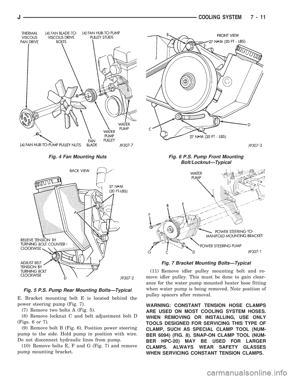
E. Bracket mounting bolt E is located behind the
power steering pump (Fig. 7).
(7) Remove two bolts A (Fig. 5).
(8) Remove locknut C and belt adjustment bolt D
(Figs. 6 or 7).
(9) Remove bolt B (Fig. 6). Position power steering
pump to the side. Hold pump in position with wire.
Do not disconnect hydraulic lines from pump.
(10) Remove bolts E, F and G (Fig. 7) and remove
pump mounting bracket.(11) Remove idler pulley mounting bolt and re-
move idler pulley. This must be done to gain clear-
ance for the water pump mounted heater hose fitting
when water pump is being removed. Note position of
pulley spacers after removal.
WARNING: CONSTANT TENSION HOSE CLAMPS
ARE USED ON MOST COOLING SYSTEM HOSES.
WHEN REMOVING OR INSTALLING, USE ONLY
TOOLS DESIGNED FOR SERVICING THIS TYPE OF
CLAMP, SUCH AS SPECIAL CLAMP TOOL (NUM-
BER 6094) (FIG. 8). SNAP-ON CLAMP TOOL (NUM-
BER HPC-20) MAY BE USED FOR LARGER
CLAMPS. ALWAYS WEAR SAFETY GLASSES
WHEN SERVICING CONSTANT TENSION CLAMPS.
Fig. 4 Fan Mounting Nuts
Fig. 5 P.S. Pump Rear Mounting BoltsÐTypical
Fig. 6 P.S. Pump Front Mounting
Bolt/LocknutÐTypical
Fig. 7 Bracket Mounting BoltsÐTypical
JCOOLING SYSTEM 7 - 11