1994 JEEP CHEROKEE lamps
[x] Cancel search: lampsPage 47 of 1784
XJ FRONT SUSPENSION
INDEX
page page
Axle Bushing Replacement................. 11
Coil Spring............................. 13
Lower Suspension Arm.................... 11
Service Information....................... 10
Shock Absorber.......................... 12Spring and Shock Diagnosis................ 12
Stabilizer Bar............................ 10
Track Bar.............................. 10
Upper Suspension Arm.................... 11
SERVICE INFORMATION
CAUTION: Suspension components that use rubber
bushings should be tightened with the vehicle at
the normal height. It is important to have the
springs supporting the weight of the vehicle when
the fasteners are torqued. If the springs are not at
their normal ride position, vehicle ride comfort
could be affected along with premature bushing
wear. Rubber bushings must never be lubricated.
TRACK BAR
REMOVAL
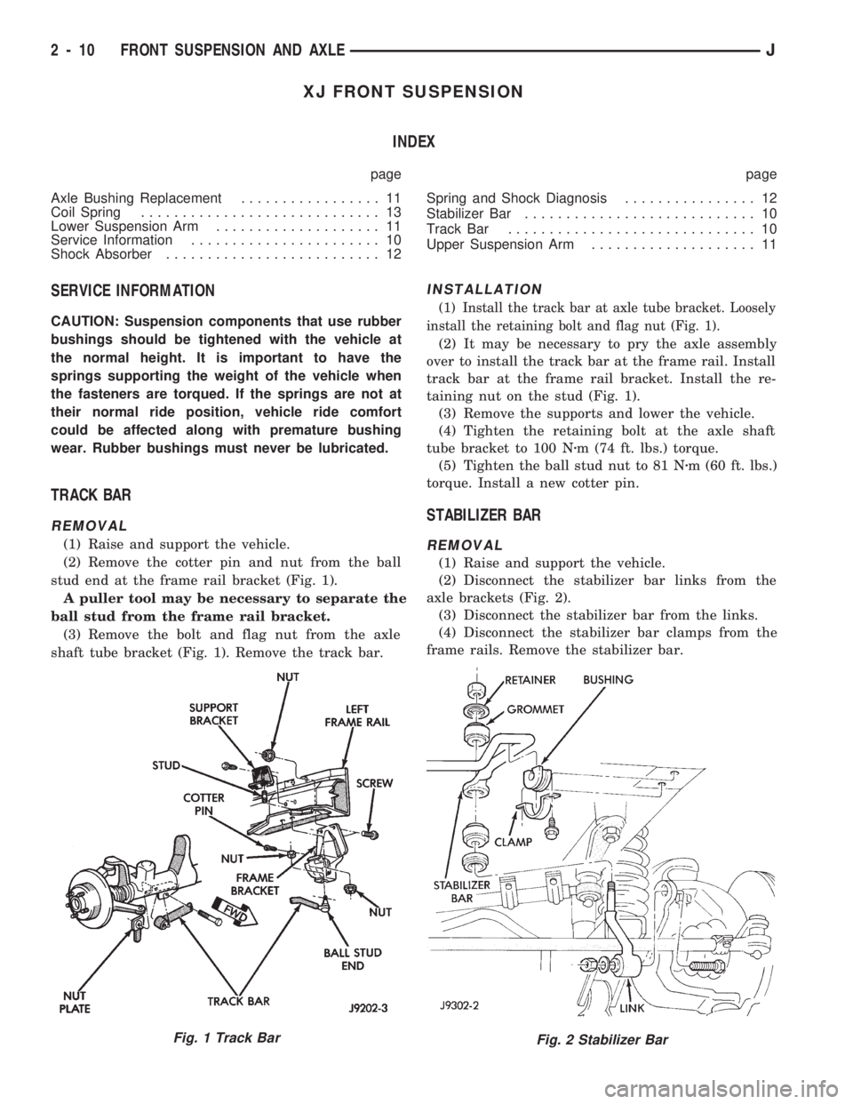
(1) Raise and support the vehicle.
(2) Remove the cotter pin and nut from the ball
stud end at the frame rail bracket (Fig. 1).
A puller tool may be necessary to separate the
ball stud from the frame rail bracket.
(3) Remove the bolt and flag nut from the axle
shaft tube bracket (Fig. 1). Remove the track bar.
INSTALLATION
(1) Install the track bar at axle tube bracket. Loosely
install the retaining bolt and flag nut (Fig. 1).
(2) It may be necessary to pry the axle assembly
over to install the track bar at the frame rail. Install
track bar at the frame rail bracket. Install the re-
taining nut on the stud (Fig. 1).
(3) Remove the supports and lower the vehicle.
(4) Tighten the retaining bolt at the axle shaft
tube bracket to 100 Nzm (74 ft. lbs.) torque.
(5) Tighten the ball stud nut to 81 Nzm (60 ft. lbs.)
torque. Install a new cotter pin.
STABILIZER BAR
REMOVAL
(1) Raise and support the vehicle.
(2) Disconnect the stabilizer bar links from the
axle brackets (Fig. 2).
(3) Disconnect the stabilizer bar from the links.
(4) Disconnect the stabilizer bar clamps from the
frame rails. Remove the stabilizer bar.
Fig. 2 Stabilizer BarFig. 1 Track Bar
2 - 10 FRONT SUSPENSION AND AXLEJ
Page 48 of 1784
INSTALLATION
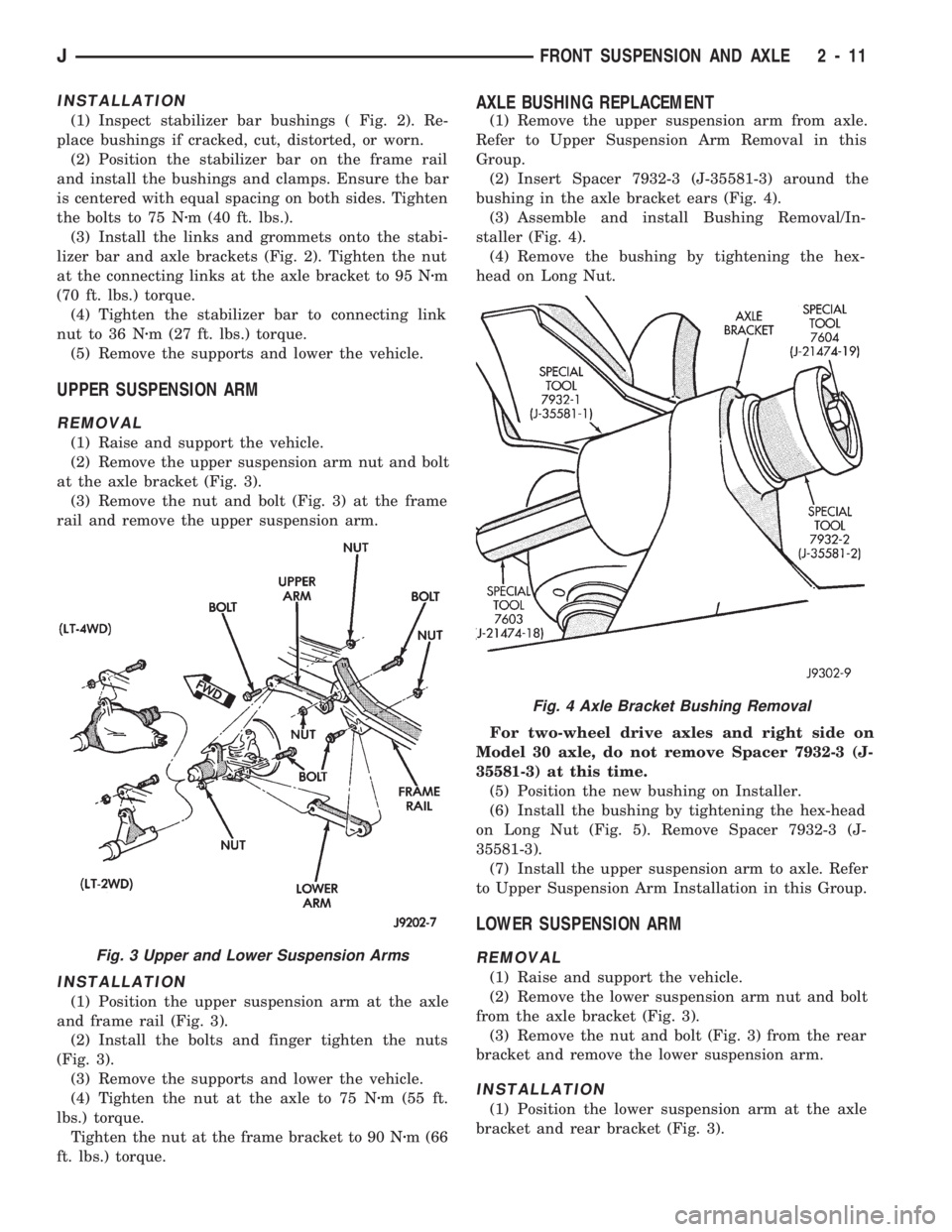
(1) Inspect stabilizer bar bushings ( Fig. 2). Re-
place bushings if cracked, cut, distorted, or worn.
(2) Position the stabilizer bar on the frame rail
and install the bushings and clamps. Ensure the bar
is centered with equal spacing on both sides. Tighten
the bolts to 75 Nzm (40 ft. lbs.).
(3) Install the links and grommets onto the stabi-
lizer bar and axle brackets (Fig. 2). Tighten the nut
at the connecting links at the axle bracket to 95 Nzm
(70 ft. lbs.) torque.
(4) Tighten the stabilizer bar to connecting link
nut to 36 Nzm (27 ft. lbs.) torque.
(5) Remove the supports and lower the vehicle.
UPPER SUSPENSION ARM
REMOVAL
(1) Raise and support the vehicle.
(2) Remove the upper suspension arm nut and bolt
at the axle bracket (Fig. 3).
(3) Remove the nut and bolt (Fig. 3) at the frame
rail and remove the upper suspension arm.
INSTALLATION
(1) Position the upper suspension arm at the axle
and frame rail (Fig. 3).
(2) Install the bolts and finger tighten the nuts
(Fig. 3).
(3) Remove the supports and lower the vehicle.
(4) Tighten the nut at the axle to 75 Nzm (55 ft.
lbs.) torque.
Tighten the nut at the frame bracket to 90 Nzm (66
ft. lbs.) torque.
AXLE BUSHING REPLACEMENT
(1) Remove the upper suspension arm from axle.
Refer to Upper Suspension Arm Removal in this
Group.
(2) Insert Spacer 7932-3 (J-35581-3) around the
bushing in the axle bracket ears (Fig. 4).
(3) Assemble and install Bushing Removal/In-
staller (Fig. 4).
(4) Remove the bushing by tightening the hex-
head on Long Nut.
For two-wheel drive axles and right side on
Model 30 axle, do not remove Spacer 7932-3 (J-
35581-3) at this time.
(5) Position the new bushing on Installer.
(6) Install the bushing by tightening the hex-head
on Long Nut (Fig. 5). Remove Spacer 7932-3 (J-
35581-3).
(7) Install the upper suspension arm to axle. Refer
to Upper Suspension Arm Installation in this Group.
LOWER SUSPENSION ARM
REMOVAL
(1) Raise and support the vehicle.
(2) Remove the lower suspension arm nut and bolt
from the axle bracket (Fig. 3).
(3) Remove the nut and bolt (Fig. 3) from the rear
bracket and remove the lower suspension arm.
INSTALLATION
(1) Position the lower suspension arm at the axle
bracket and rear bracket (Fig. 3).
Fig. 3 Upper and Lower Suspension Arms
Fig. 4 Axle Bracket Bushing Removal
JFRONT SUSPENSION AND AXLE 2 - 11
Page 51 of 1784
STABILIZER BAR
REMOVAL
(1) Raise and support the vehicle.
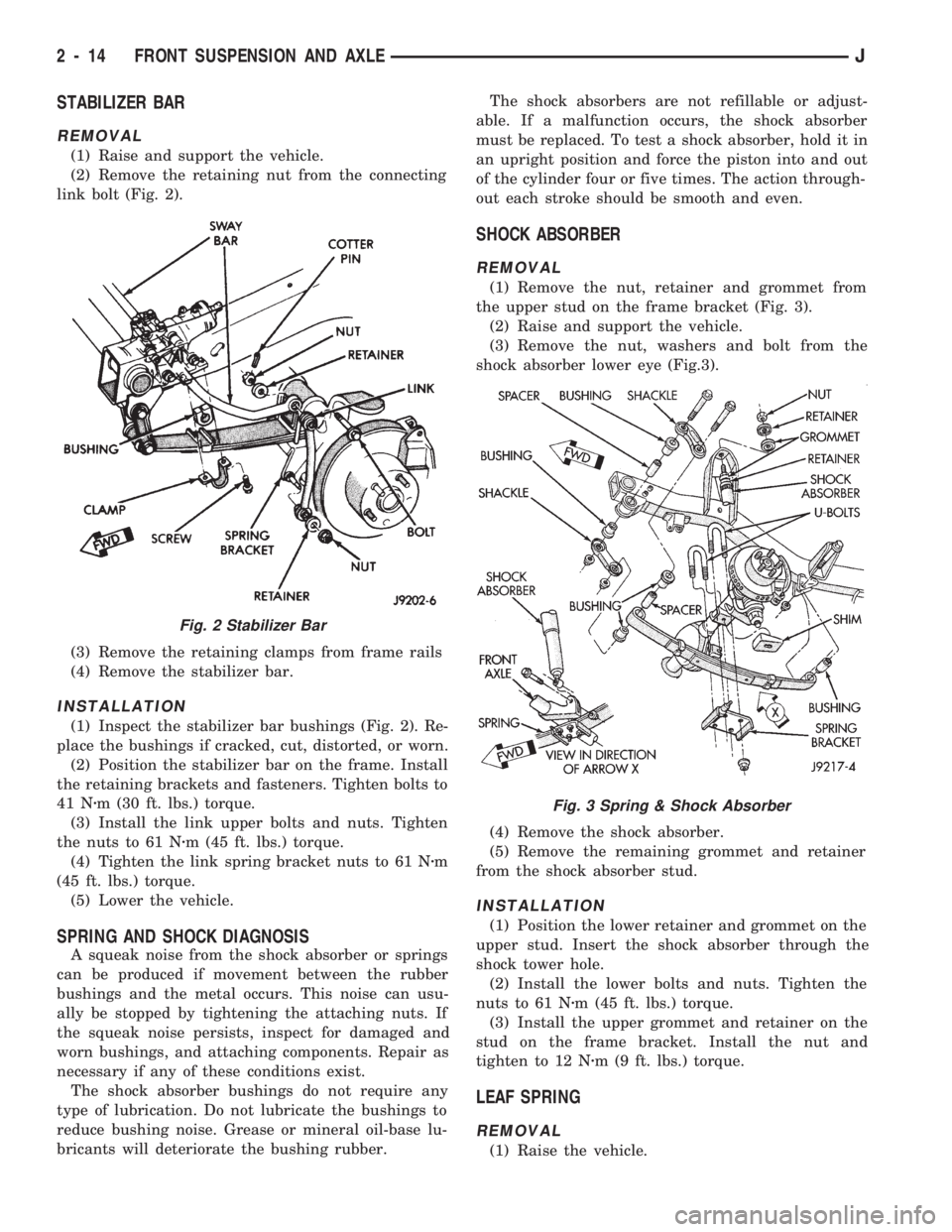
(2) Remove the retaining nut from the connecting
link bolt (Fig. 2).
(3) Remove the retaining clamps from frame rails
(4) Remove the stabilizer bar.
INSTALLATION
(1) Inspect the stabilizer bar bushings (Fig. 2). Re-
place the bushings if cracked, cut, distorted, or worn.
(2) Position the stabilizer bar on the frame. Install
the retaining brackets and fasteners. Tighten bolts to
41 Nzm (30 ft. lbs.) torque.
(3) Install the link upper bolts and nuts. Tighten
the nuts to 61 Nzm (45 ft. lbs.) torque.
(4) Tighten the link spring bracket nuts to 61 Nzm
(45 ft. lbs.) torque.
(5) Lower the vehicle.
SPRING AND SHOCK DIAGNOSIS
A squeak noise from the shock absorber or springs
can be produced if movement between the rubber
bushings and the metal occurs. This noise can usu-
ally be stopped by tightening the attaching nuts. If
the squeak noise persists, inspect for damaged and
worn bushings, and attaching components. Repair as
necessary if any of these conditions exist.
The shock absorber bushings do not require any
type of lubrication. Do not lubricate the bushings to
reduce bushing noise. Grease or mineral oil-base lu-
bricants will deteriorate the bushing rubber.The shock absorbers are not refillable or adjust-
able. If a malfunction occurs, the shock absorber
must be replaced. To test a shock absorber, hold it in
an upright position and force the piston into and out
of the cylinder four or five times. The action through-
out each stroke should be smooth and even.
SHOCK ABSORBER
REMOVAL
(1) Remove the nut, retainer and grommet from
the upper stud on the frame bracket (Fig. 3).
(2) Raise and support the vehicle.
(3) Remove the nut, washers and bolt from the
shock absorber lower eye (Fig.3).
(4) Remove the shock absorber.
(5) Remove the remaining grommet and retainer
from the shock absorber stud.
INSTALLATION
(1) Position the lower retainer and grommet on the
upper stud. Insert the shock absorber through the
shock tower hole.
(2) Install the lower bolts and nuts. Tighten the
nuts to 61 Nzm (45 ft. lbs.) torque.
(3) Install the upper grommet and retainer on the
stud on the frame bracket. Install the nut and
tighten to 12 Nzm (9 ft. lbs.) torque.
LEAF SPRING
REMOVAL
(1) Raise the vehicle.
Fig. 2 Stabilizer Bar
Fig. 3 Spring & Shock Absorber
2 - 14 FRONT SUSPENSION AND AXLEJ
Page 69 of 1784
(4) Install the Hub Bearing and Axle Shaft accord-
ing to the installation procedure.
(5) Reconnect the tie-rod or drag link end onto the
steering knuckle arm. Install the ABS sensor wire
and bracket to the knuckle, refer to Group 5 Ð
Brakes.
AXLE BUSHING REPLACEMENT
Refer to Axle Bushing Replacement in the Front
Suspension section.
DIFFERENTIAL REMOVAL
To service the differential the axle assembly and
axle shafts must be removed. Refer to the removal
procedures in this Group.
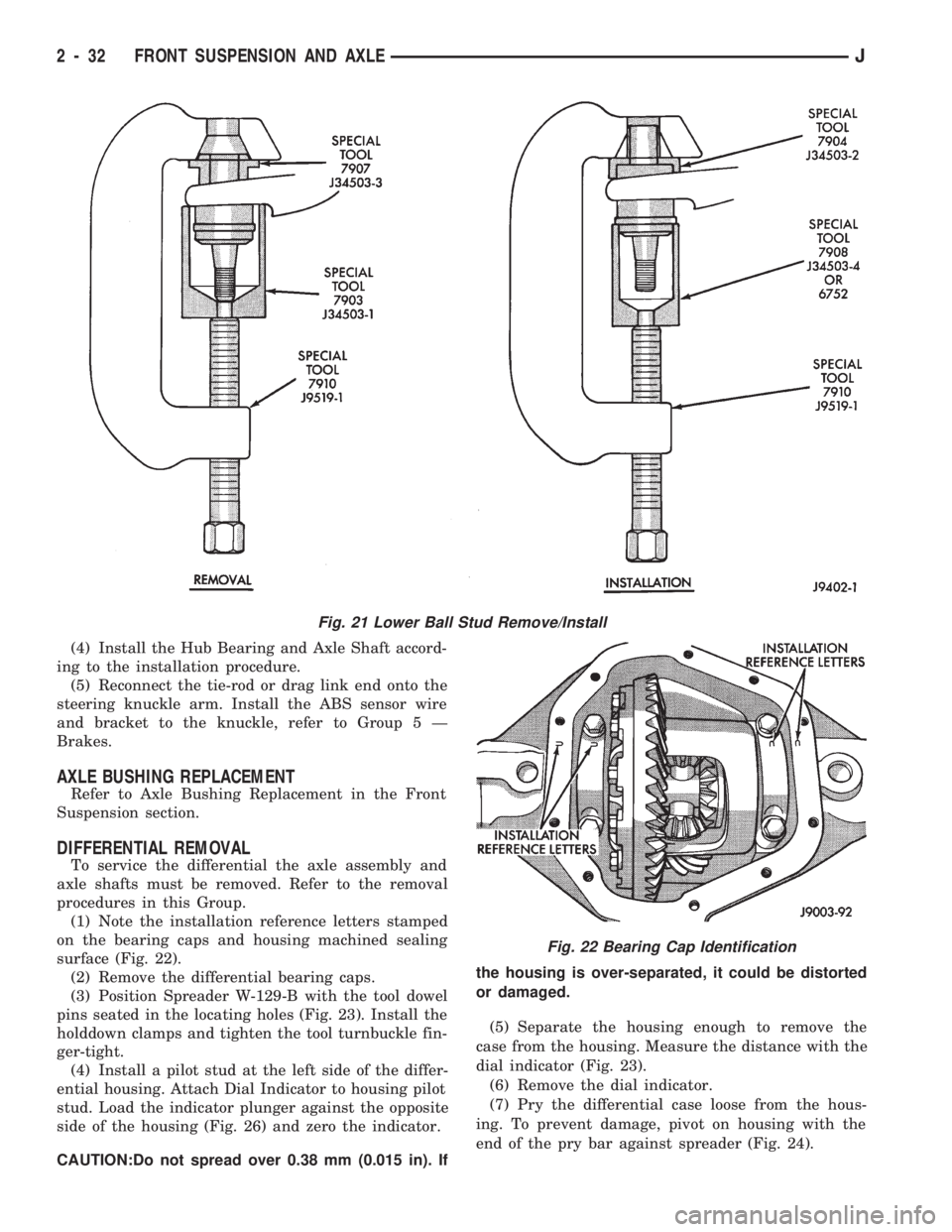
(1) Note the installation reference letters stamped
on the bearing caps and housing machined sealing
surface (Fig. 22).
(2) Remove the differential bearing caps.
(3) Position Spreader W-129-B with the tool dowel
pins seated in the locating holes (Fig. 23). Install the
holddown clamps and tighten the tool turnbuckle fin-
ger-tight.
(4) Install a pilot stud at the left side of the differ-
ential housing. Attach Dial Indicator to housing pilot
stud. Load the indicator plunger against the opposite
side of the housing (Fig. 26) and zero the indicator.
CAUTION:Do not spread over 0.38 mm (0.015 in). Ifthe housing is over-separated, it could be distorted
or damaged.
(5) Separate the housing enough to remove the
case from the housing. Measure the distance with the
dial indicator (Fig. 23).
(6) Remove the dial indicator.
(7) Pry the differential case loose from the hous-
ing. To prevent damage, pivot on housing with the
end of the pry bar against spreader (Fig. 24).
Fig. 21 Lower Ball Stud Remove/Install
Fig. 22 Bearing Cap Identification
2 - 32 FRONT SUSPENSION AND AXLEJ
Page 80 of 1784
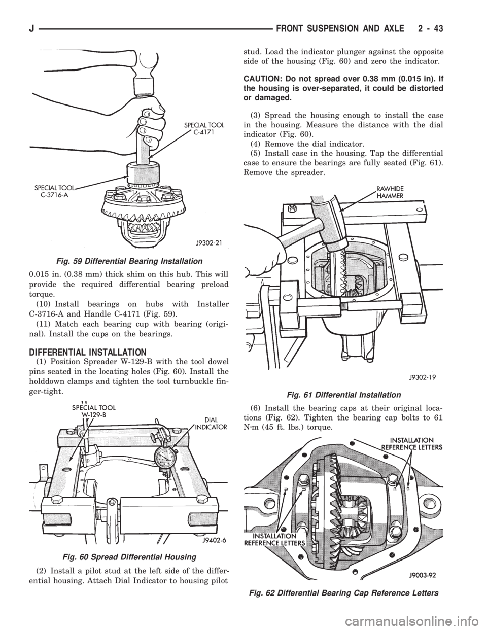
0.015 in. (0.38 mm) thick shim on this hub. This will
provide the required differential bearing preload
torque.
(10) Install bearings on hubs with Installer
C-3716-A and Handle C-4171 (Fig. 59).
(11) Match each bearing cup with bearing (origi-
nal). Install the cups on the bearings.
DIFFERENTIAL INSTALLATION
(1) Position Spreader W-129-B with the tool dowel
pins seated in the locating holes (Fig. 60). Install the
holddown clamps and tighten the tool turnbuckle fin-
ger-tight.
(2) Install a pilot stud at the left side of the differ-
ential housing. Attach Dial Indicator to housing pilotstud. Load the indicator plunger against the opposite
side of the housing (Fig. 60) and zero the indicator.
CAUTION: Do not spread over 0.38 mm (0.015 in). If
the housing is over-separated, it could be distorted
or damaged.
(3) Spread the housing enough to install the case
in the housing. Measure the distance with the dial
indicator (Fig. 60).
(4) Remove the dial indicator.
(5) Install case in the housing. Tap the differential
case to ensure the bearings are fully seated (Fig. 61).
Remove the spreader.
(6) Install the bearing caps at their original loca-
tions (Fig. 62). Tighten the bearing cap bolts to 61
Nzm (45 ft. lbs.) torque.
Fig. 59 Differential Bearing Installation
Fig. 60 Spread Differential Housing
Fig. 61 Differential Installation
Fig. 62 Differential Bearing Cap Reference Letters
JFRONT SUSPENSION AND AXLE 2 - 43
Page 87 of 1784

line. You may encounter fuels containing 3 percent
or more methanol along with other alcohols called co-
solvents.
Problems that are the result of using methanol/gas-
oline blends are not the responsibility of Chrysler
Corporation. They may not be covered by the vehicle
warranty.
MTBE/ETBE
Gasoline and MTBE (Methyl Tertiary Butyl Ether)
blends are a mixture of unleaded gasoline and up to
15 percent MTBE. Gasoline and ETBE (Ethyl Ter-
tiary Butyl Ether) are blends of gasoline and up to
17 percent ETBE. Gasoline blended with MTBE or
ETBE may be used in your vehicle.CLEAN AIR GASOLINE
Many gasolines are now being blended that con-
tribute to cleaner air, especially in those areas of the
country where air pollution levels are high. These
new blends provide a cleaner burning fuel and some
are referred to asReformulated Gasoline.
In areas of the country where carbon monoxide lev-
els are high, gasolines are being treated with oxy-
genated materials such as MTBE, ETBE and
ethanol.
Chrysler Corporation supports these efforts toward
cleaner air and recommends that you use these gas-
olines as they become available.
FUEL DELIVERY SYSTEM
INDEX
page page
Fuel Filter............................... 8
Fuel Pressure Leak Down Test............... 7
Fuel Pressure Release Procedure............. 5
Fuel Pump Capacity Test................... 7
Fuel Pump Electrical Control................. 5Fuel Pump Module........................ 2
Fuel System Pressure Test.................. 5
Fuel Tubes/Lines/Hoses and Clamps........... 9
Quick-Connect Fittings..................... 9
FUEL PUMP MODULE
The fuel pump module is installed in the top of the
fuel tank. The fuel pump module contains the follow-
ing components:
²Electric fuel pump
²Fuel pump reservoir
²In-tank fuel filter
²Fuel gauge sending unit
²Fuel supply and return tube connections
The fuel pump used on all vehicles is a gear/rotor
type pump. It is driven by a permanent magnet 12
volt electric motor that is immersed in the fuel tank.
The electrical pump is integral with the fuel sender
unit. The pump/sender assembly is installed inside
the fuel tank.
The fuel pump has a check valve at the outlet end
that consists of a ball held against a seat by force ap-
plied from a spring. When the pump is operating,
fuel pressure overcomes spring pressure and forces
the ball off its seat, allowing fuel to flow. When the
pump is not operating, spring pressure forces the ball
back against the seat preventing fuel backflow
through the pump.
Fuel system pressure is maintained at approxi-
mately 214 kPa (31 psi). This is when the pump is
operating and vacuum is supplied to the fuel pres-
sure regulator. If vacuum is not supplied to the pres-
sure regulator, fuel pressure will be approximately
55-69 kPa (8-10 psi) higher. This may be due to a
broken or clogged vacuum line. When the fuel pumpis not operating, system fuel pressure of 131-269 kPa
(19-39 psi) is maintained. This is done by the fuel
pump outlet check valve and the vacuum assisted
fuel pressure regulator.
REMOVALÐXJ MODELS
The fuel pump/gauge sender unit assembly can be
removed from the fuel tank without removing the
tank from the vehicle.
WARNING: THE FUEL SYSTEM IS UNDER A CON-
STANT PRESSURE (EVEN WITH THE ENGINE OFF).
BEFORE SERVICING THE FUEL PUMP MODULE,
THE FUEL SYSTEM PRESSURE MUST BE RE-
LEASED. REFER TO THE FUEL PRESSURE RE-
LEASE PROCEDURE IN THIS GROUP.
WARNING: EXTINGUISH ALL TOBACCO SMOKING
PRODUCTS BEFORE SERVICING THE FUEL SYS-
TEM. KEEP OPEN FLAME AWAY FROM FUEL SYS-
TEM COMPONENTS.
(1) Remove fuel filler cap. Perform the Fuel Pres-
sure Release Procedure as outlined in this group.
(2) Disconnect negative battery cable.
(3) Using an approved portable gasoline siphon/
storage tank, drain fuel tank until fuel level is below
one quarter (1/4) full.
(4) Raise and support vehicle.
14 - 2 FUEL SYSTEMJ
Page 88 of 1784
WARNING: WRAP SHOP TOWELS AROUND FUEL
HOSES TO ABSORB ANY FUEL SPILLAGE DURING
FUEL TANK REMOVAL.
(5) Disconnect fuel vent supply and return tubes
from fittings on fuel pump module.
(6) Disconnect fuel pump module electrical harness
connector from main harness.
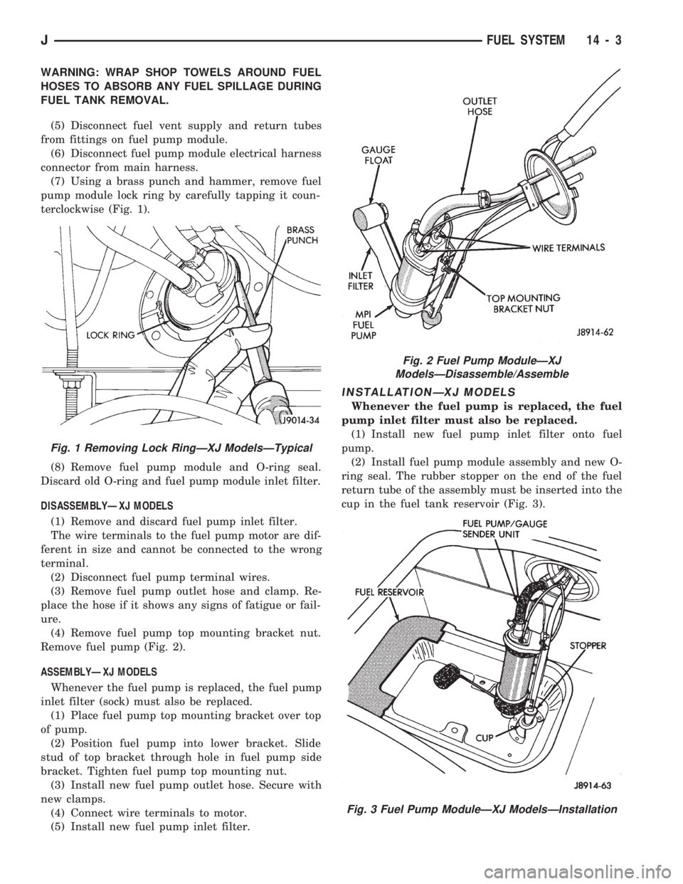
(7) Using a brass punch and hammer, remove fuel
pump module lock ring by carefully tapping it coun-
terclockwise (Fig. 1).
(8) Remove fuel pump module and O-ring seal.
Discard old O-ring and fuel pump module inlet filter.
DISASSEMBLYÐXJ MODELS
(1) Remove and discard fuel pump inlet filter.
The wire terminals to the fuel pump motor are dif-
ferent in size and cannot be connected to the wrong
terminal.
(2) Disconnect fuel pump terminal wires.
(3) Remove fuel pump outlet hose and clamp. Re-
place the hose if it shows any signs of fatigue or fail-
ure.
(4) Remove fuel pump top mounting bracket nut.
Remove fuel pump (Fig. 2).
ASSEMBLYÐXJ MODELS
Whenever the fuel pump is replaced, the fuel pump
inlet filter (sock) must also be replaced.
(1) Place fuel pump top mounting bracket over top
of pump.
(2) Position fuel pump into lower bracket. Slide
stud of top bracket through hole in fuel pump side
bracket. Tighten fuel pump top mounting nut.
(3) Install new fuel pump outlet hose. Secure with
new clamps.
(4) Connect wire terminals to motor.
(5) Install new fuel pump inlet filter.
INSTALLATIONÐXJ MODELS
Whenever the fuel pump is replaced, the fuel
pump inlet filter must also be replaced.
(1) Install new fuel pump inlet filter onto fuel
pump.
(2) Install fuel pump module assembly and new O-
ring seal. The rubber stopper on the end of the fuel
return tube of the assembly must be inserted into the
cup in the fuel tank reservoir (Fig. 3).
Fig. 1 Removing Lock RingÐXJ ModelsÐTypical
Fig. 2 Fuel Pump ModuleÐXJ
ModelsÐDisassemble/Assemble
Fig. 3 Fuel Pump ModuleÐXJ ModelsÐInstallation
JFUEL SYSTEM 14 - 3
Page 89 of 1784
(3) Using a brass punch and a hammer, install
lock ring. Carefully tap lock ring clockwise until it
seats against stop on fuel tank.
(4) Connect fuel supply and return hoses to fittings
on fuel pump module. Tighten hose clamps.
(5) Connect fuel pump module electrical harness
connector to main harness connector.
(6) Lower vehicle.
(7) Fill fuel tank. Install fuel tank cap.
(8) Connect negative battery cable.
(9) Start vehicle and inspect for leaks.
REMOVALÐYJ MODELS
The fuel tank must be removed to remove the fuel
pump module.
WARNING: THE FUEL SYSTEM IS UNDER A CON-
STANT PRESSURE (EVEN WITH THE ENGINE OFF).
BEFORE SERVICING THE FUEL PUMP MODULE,
THE FUEL SYSTEM PRESSURE MUST BE RE-
LEASED. REFER TO THE FUEL PRESSURE RE-
LEASE PROCEDURE IN THIS GROUP.
WARNING: EXTINGUISH ALL TOBACCO SMOKING
PRODUCTS BEFORE SERVICING THE FUEL SYS-
TEM. KEEP OPEN FLAME AWAY FROM FUEL SYS-
TEM COMPONENTS.
(1) Remove negative battery cable.
(2) Remove fuel filler cap. Perform the Fuel Pres-
sure Release Procedure as outlined in this group.
(3) Remove fuel tank. Refer to Fuel Tank Remov-
alÐYJ Models.
(4) Remove fuel pump module assembly.
(5) Remove mounting screws. Lift assembly and
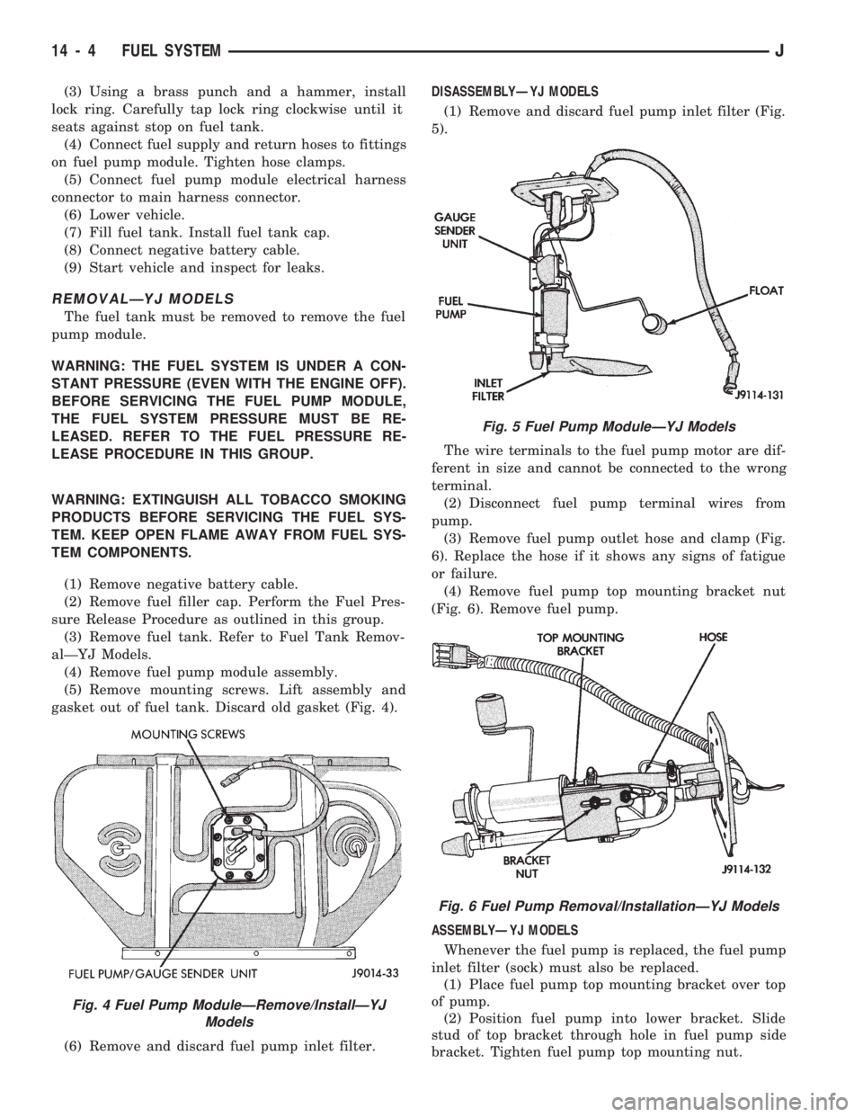
gasket out of fuel tank. Discard old gasket (Fig. 4).
(6) Remove and discard fuel pump inlet filter.DISASSEMBLYÐYJ MODELS
(1) Remove and discard fuel pump inlet filter (Fig.
5).
The wire terminals to the fuel pump motor are dif-
ferent in size and cannot be connected to the wrong
terminal.
(2) Disconnect fuel pump terminal wires from
pump.
(3) Remove fuel pump outlet hose and clamp (Fig.
6). Replace the hose if it shows any signs of fatigue
or failure.
(4) Remove fuel pump top mounting bracket nut
(Fig. 6). Remove fuel pump.
ASSEMBLYÐYJ MODELS
Whenever the fuel pump is replaced, the fuel pump
inlet filter (sock) must also be replaced.
(1) Place fuel pump top mounting bracket over top
of pump.
(2) Position fuel pump into lower bracket. Slide
stud of top bracket through hole in fuel pump side
bracket. Tighten fuel pump top mounting nut.
Fig. 4 Fuel Pump ModuleÐRemove/InstallÐYJ
Models
Fig. 5 Fuel Pump ModuleÐYJ Models
Fig. 6 Fuel Pump Removal/InstallationÐYJ Models
14 - 4 FUEL SYSTEMJ